Lisbon, Portugal, 12 – 15 July, 2017
MODELLING STRAIN PENETRATION EFFECTS IN RC WALLS
WITH SMOOTH STEEL BARS
C. Caruso*, R. Bento*, A.A. Correia** and R. Sousa**
* Department of Civil Engineering, Architecture and Georesources, CERIS, Instituto Superior Técnico, Universidade de Lisboa, Portugal
e-mails: [email protected], [email protected] ** National Laboratory of Civil Engineering (LNEC), Portugal
e-mails: [email protected], [email protected]
Keywords: Numerical modelling; Smooth reinforcing bars; Concrete–steel bond.
Abstract. Reinforced concrete (RC) framed and dual wall-frame structures represent an important
fraction of the building stock in some European cities. Many of these were constructed without seismic provisions. Therefore, it is important to assess their ability to withstand seismic events and to define strategies to reduce their potential vulnerability. This work focuses on the numerical simulation of the seismic behaviour of RC walls making use of fibre-based nonlinear beam-column elements. Even though it is common to assume a perfect bond between the reinforcing bars and concrete, the relative bond-slip deformations between the two materials can contribute up to 40% of the total lateral deformation of columns when ribbed rebars are used and up to 90% when in the presence of smooth rebars. This paper intends to be a contribution to understand the importance of these effects in old RC walls, namely through the consideration of both ribbed and smooth rebars with different anchorage lengths and provide indications regarding the use of a simplified bond-slip model.
1 INTRODUCTION
An important number of RC framed and dual wall-frame RC structures in southern Europe, including Portugal, were constructed between 1960's and 1980’s, before the introduction of modern seismic codes. Considering their potential seismic vulnerability, it seems important to evaluate the validity of different numerical models that can be used to assess the seismic performance of these RC walls, in particular the ones featuring smooth rebars.
Beam-column types of elements are widely used to simulate the nonlinear response of structures. The application of such finite element formulation has proved to be adequate for framed structures, combining the accuracy in the estimation of global response parameters with an appreciable computational efficiency. However, whilst slender framed elements tend to exhibit a response dominated by their flexural component, the response of wall structures combines other deformation mechanisms, such as shear deformations, that are difficult to be explicitly modelled with beam-column elements. In addition, limited investigation has been carried out so far to assess the contribution of strain penetration (SP) effects at the anchorage region of RC walls.
Hence, this work is focused on the numerical simulation of RC walls, with particular focus on the importance of SP effects to the seismic behaviour of these elements. These effects cause fixed-end rotations at wall-foundation interface, which can represent an important contribution to the total lateral deformation of the member. Previous studies on RC columns,
e.g. [1] and [2], indicate that SP deformations can contribute up to 40% of the total lateral
deformation of columns when ribbed rebars are used. On the other hand, experimental tests conducted on both RC columns [3] and beam-column joints [4] with smooth rebars reveal that this mechanism may contribute to nearly 90% of the overall member deformation at failure.
These results show that these phenomena can be particularly relevant in older RC members, which are often characterized by inadequate detailing, insufficient anchorage lengths or the presence of smooth rebars.
This study starts with a brief review of the literature in what regards the use of distributed plasticity models, namely regarding the importance of shear deformations and SP effects. The consideration of different element formulations of distributed plasticity models is then analysed comparing the respective numerical response against the experimental results of a slender RC wall tested in the past by Dazio et al. [5]. Subsequently, these numerical models are used to explore the consideration of different anchorage conditions such as rebar surface (ribbed or smooth) and different embedment lengths. Ultimately, this paper provides practical recommendations and simplified solutions to model the nonlinear response of RC walls, which can be used in engineering practice to model the seismic response of existing RC buildings.
2 MODELLING ISSUES ASSOCIATED WITH THE NUMERICAL SIMULATION OF RC WALLS
2.1 Element formulation
Contrarily to slender columns, whose behaviour is essentially governed by flexural mechanisms, the seismic response of RC walls is more complex and their failure mode can be expressed through flexural, diagonal tension, diagonal compression or sliding shear failure [6]. Quasi-static cyclic tests on slender RC walls from Dazio et al. [5] showed that the shear to flexural deformation varies between 5 and 13%. Moreover, for increasing displacement demand, shear to flexure deformation ratio tends to remain approximately constant if the shear capacity of the walls does not significantly degrade [7].
The structural behaviour of RC walls depends largely on their geometric characteristics, namely the shear span-to-depth ratio. In general, for ratios larger than 3, RC walls are classified as slender walls, and are essentially controlled by flexural behaviour. In this case the impact of shear deformation on global engineering demand parameters, like member forces and inter-storey drift displacements, will be typically small and can possibly be neglected. For smaller shear span ratios, walls are considered as squat and shear deformations are expected to play an increasing role in the member response [8].
The above discussion is particularly relevant when selecting the numerical tool to model these RC walls. The employment of lumped and distributed plasticity elements offer an accurate and efficient solution to model the nonlinear behaviour of slender RC elements. However, considering their limitations to account for shear deformations, their application to walls should deserve additional attention. On the other hand, advanced modelling approaches, such as solid or shell elements, are capable to account directly for the interaction between axial force, flexure and shear, but are computationally demanding and not used in common engineering practice. For the sake of knowledge, a state of art-review of different macro-modelling approach for RC walls was presented by Wu et al. [10], addressing important modelling issues, including the interaction between flexure and shear.
In this framework it is worth to refer a study developed by Almeida et al. [11], regarding the identification of the most suited approach for modelling the inelastic behaviour of RC walls. In this study, shell element models were used as benchmark to assess the extent to which pure flexural models, such as beam elements, can capture the response of elements that have non-negligible shear deformations. The outcome of this work shows that, for slender walls, where a predominant flexural response is expected, the computation of global
quantities, such as stiffness up to peak and force is moderately sensitive to the different modelling approaches.
Considering the above limitations, and before addressing the simulation of SP effects, the numerical response of the RC wall was firstly validated through a comparison of the numerical response, featuring different formulation and discretization schemes, against the experimental response of an RC wall subjected to experimental tests in the past. This preliminary study is described in more detail in Section 3.2.
2.2 Strain Penetration effects
RC members subjected to seismic loading can show localized deformation occurring between the reinforcement and the concrete of adjacent members. The transfer mechanism of rebar forces to the surrounding concrete occurs due to chemical adhesion between steel and concrete, frictional forces at the interface between both materials and bearing force of the ribs against the concrete [12]. These phenomena are generally referred to as SP or bond-slip effects and lead to the development of an additional rotation at the extremity of the members, when these are subjected to lateral loads.
This fixed-end rotation results from the spread of the rebars strains through the anchorage region, which causes strain incompatibility between the reinforcement and the surrounding concrete. To limit these deformations, it is necessary to provide a sufficiently long embedment length (Le) allowing the transfer of the axial load at the rebar to the surrounding
concrete through the contact surface. Whenever the embedment length is insufficient, the rebar experiences an important increase of slip, leading to a large increase of the element’s base rotation or even failure of the anchorage system (Figure 1).
Figure 1: Behaviour of anchorage region with adequate (left) and limited (right) embedment length (adapted from [20]).
Generally, the numerical simulation of RC structures assumes a perfect bond between the two materials. However, for increasing loads demand, breaking of the bond occurs and bond-slip between reinforcing steel and surrounding concrete takes place. Even though relatively large anchorage lengths are provided, avoiding the failure of the anchorage system, these deformations can represent an important contribution to the global deformations of the members (e.g., [13], [14], [1] and [2]). In older RC structures, with inadequate anchorage detailing and/or smooth rebars, with much reduced bond strength, these effects become more relevant, as noted by Verderame et al. [3] and Melo et al. [4].
Despite the recognized contribution of SP effects to the overall member’s deformations, the numerical models available to simulate these nonlinear effects are still very limited. Although these effects can be explicitly simulated in finite element software featuring highly discretized solid elements capable of describing the anchorage region (e.g., [15], [16], [17], [18] and [19]), conventional beam elements formulation does not allow modelling the interface between the reinforcement and the surrounding concrete. To overcome these limitations, several studies have been conducted in the recent years to develop models compatible with beam elements formulation capable of accounting for the bond-slip effects
(e.g., [1], [20], [21] and [22]). Despite the number of studies developed, only a few have been incorporated in commercial software packages used by practitioners. The interested reader can find a description of some of these models in [12].
Considering the previous limitations, engineering practitioners often resort to simplified modelling approaches such as the elongation of the structural element by the strain penetration length or the definition of linear rotational springs at the extremities of the elements. Despite the improvements in the computed response, the former approaches present important limitations, namely the change in the elastic properties of the structure or the underestimation of the shear forces developed at the element [23].
An alternative, and simpler approach, involves the modification of the reinforcing steel constitutive law. According to [24], it is possible to take into account the bond-slip effect through a correction factor ( ) that modifies the reinforcement constitutive law. This slippage factor represents the ratio between concrete and steel strain (Equation 1), and expresses the correction of the average steel strain in a RC finite element [24]. According to this proposal, the steel constitutive law is assumed to be bilinear with an elastic perfectly-plastic behaviour, as represented in Figure 2. In turn, Equation 2 to 4 express, respectively, the modifications in the strain, stress and modulus of elasticity of the steel, to account for the bond-slip effect ([24] and [25]).
Figure 2: Correction of the steel reinforcing law (adapted from [24]).
At the current state-of-the-art, these models lack clear application guidance. Furthermore, they require additional calibration with the aim of adjusting the different parameters to alternative element typology and anchorage conditions, such as the presence of smooth rebars or insufficient anchorage length. As an attempt to contribute to minimize these limitations, the following section presents a case study where the response of one RC wall, submitted to experimental cyclic tests, is numerically simulated considering different anchorage conditions. The outcome of these analyses provides indicative parameters to modify the reinforcing steel constitutive law in order to take into account the bond-slip effects under different loading conditions.
(1)
(2, 3, 4)
3 CASE STUDY
3.1 Description of the experimental test
In the current study, the wall specimen WSH4 analysed by Dazio et al. [5] was numerically modelled and subjected to pushover analysis. The characteristics of the RC wall specimen are
representative of constructions without seismic detailing, with total reinforcement ratio typically smaller than 1%, a relatively low axial load ratio (N/Agfc) and limited ductility
properties of the longitudinal reinforcement. In addition, the wall has no confining or stabilising reinforcement, i.e. it was not specifically designed for ductile behaviour. The test unit is 2.00 m long and 0.15 m wide. The length of the shear span is 4.56 m for a shear span ratio of 2.28 m. The details of the reinforcement (ribbed rebars) are shown in Figure 3, whilst Table 1 and Table 2 summarize the information regarding the axial force, reinforcement ratios and material properties. A detailed description of the test can be found in [5].
Figure 3: Reinforcement layout in the plastic zone of the wall WSH4. All dimensions in mm. (Adapted from Dazio et al., 2008).
Table 1: Summary of test unit WSH4 properties.
Sectional forces at the base Reinforcement rations
N (kN) N/Agfc (-) ρbound (%) ρweb (%) ρtot (%) ρh (%)
695 0.057 1.54 0.54 0.82 0.25
ρbound - boundary reinforcement; ρweb - web reinforcement; ρtot - total reinforcement ratio; ρh - horizontal reinforcement
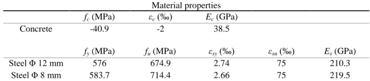
Table 2: Summary of test unit WSH4 material properties.
Material properties
fc (MPa) εc (‰) Ec (GPa)
Concrete -40.9 -2 38.5
fy (MPa) fu (MPa) εsy (‰) εsu (‰) Es (GPa)
Steel Φ 12 mm 576 674.9 2.74 75 210.3
Steel Φ 8 mm 583.7 714.4 2.66 75 219.5
Concrete: fc – maximum strength; εc – strain at maximum strength; Ec - modulus of elasticity
Steel: fy - yield strength; fu - ultimate strength; εsy, - yield strain; εsu – ultimate strain; Es - modulus of elasticity
3.2 Numerical modelling options
Before addressing the numerical simulation of strain penetration effects, it is fundamental to guarantee that the behaviour of the wall, i.e., the response of the element above the anchorage region, can be accurately represented with the consideration of beam elements with distributed plasticity. In this section, three distinct modelling options to simulate the behaviour of the cantilever wall are presented. They differ with regard to the beam element formulation and mesh discretization.
Fibre-based non-linear beam elements idealize a section into a number of discrete fibres to which a uniaxial material constitutive relation is assigned. These fibre sections are defined along the different elements through a finite number of integration points (IPs) allowing to describe the spread of inelasticity along the element. The definition of the different response parameters at the different IPs can be accomplished following a force-based (FB) or displacement-based (DB) formulation, which verifies the equilibrium in an exact and
averaged way, respectively. In this regard, and contrarily to the FB case, where a single element with a certain number of IPs can be used to compute the element response (through Gauss-Lobatto integration scheme), in the DB case, the RC member need to be discretized in several elements. In this latter case, two IPs per element are sufficient to determine the element response (through Gauss-Legendre integration scheme).
In the present study, the RC wall was modelled in the OpenSees platform [26] considering 3 different formulation/discretization schemes, namely 2 FB models and 1 DB model. Although for the FB formulation 5 IPs are generally sufficient [27], it has been shown that the post-peak element response is highly dependent on the number of IPs [11]; therefore an additional scheme with 9 IPs was also considered. Regarding the DB model, the wall was modelled with 4 elements, each one with two Gauss-Legendre IPs.
For all the cases described above, the section of the wall was discretized in 200 fibres, which corresponds to 1 fibre for each centimetre, for both cover and core. Moreover, the reinforcing steel was modelled using the uniaxial material ‘Steel02’ based on the Giuffre-Menegotto-Pinto constitutive model [28]. On the other hand, the cover and core concrete were modelled using the uniaxial material ‘Concrete 04’, which is based on the model proposed by Popovics [29]. The mechanical properties of the confined concrete were determined according to Mander et al. [30], with a geometrical effectiveness coefficient of confinement Ce = 0.5
[11].
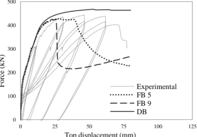
A comparison of the shear force-top displacement curves presented in Figure 4 shows a good agreement between the numerical and experimental results. Up to peak strength, the numerical predictions are very similar and are in line with the experimental results. Nonetheless, the model using FB elements appears to provide a better estimation of the peak strength than the model employing DB elements, which shows an overestimation of the maximum lateral resisting force. After the peak strength, the predictions with the different modelling approaches diverge due to a numerical pathology named localization, wherein curvatures concentrate at the most stressed sections of the elements [31].
Overall, and despite the potential limitations in the use of beam elements to model RC walls, highlighted in section 2.1, the results obtained indicate that the application of these models appear to produce reliable and acceptably accurate predictions of the behaviour of the RC wall. Based on the results obtained, the investigation of the importance of SP effects in old RC walls presented in the following section is conducted considering the numerical model featuring one force-based element with 5 IPs.
Figure 4: Shear force-top displacement for the RC wall specimen WSH4, considering both FB and DB formulation. 0 100 200 300 400 500 0 25 50 75 100 125 F o rc e (k N ) Top displacement (mm) Experimental FB 5 FB 9 DB
4 NUMERICAL RESULTS
This section presents the results of the numerical analysis conducted to evaluate the SP effect in the seismic behaviour of RC walls considering ribbed and smooth rebars with different embedment lengths. Based on the results obtained, it was possible to establish reference parameters that can be used to adjust the properties of the reinforcement constitutive models in order to implicitly reflect the SP effects in the anchorage region of RC walls.
4.1 SP effects for different anchorage conditions
Current software packages featuring beam elements, including the one used in this study, provide limited solutions to simulate SP effects, especially under specific conditions such as smooth rebars and limited anchorage length. Hence, these effects were firstly determined with the explicit bond-slip model proposed by Sousa et al. [22]. In addition to the geometric and mechanic properties of the anchorage region of the elements, this model explicitly simulates other important effects such as the cyclic degradation and rebar yielding of the embedded rebars. This element replicates the member-end section and simulates the embedded region with virtual integration points distributed along the embedment length with independent bond-slip constitutive relations based on the model proposed in Model Code 2010 [32].
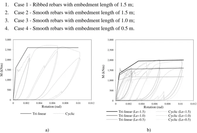
Once the moment-rotation relation associated with the bond-slip effects at the base of the RC wall is determined, a monotonic (tri-linear) law was adjusted to the computed cyclic response in order to calibrate the nonlinear rotational springs to be assigned at the base of the RC wall element modelled in OpenSees (Figure 5). The numerical simulation of the wall specimen WSH4 was conducted considering moment-rotation relationships that describe the bond-slip effects at the base of the wall for the following anchorage conditions:
1. Case 1 - Ribbed rebars with embedment length of 1.5 m; 2. Case 2 - Smooth rebars with embedment length of 1.5 m; 3. Case 3 - Smooth rebars with embedment length of 1.0 m; 4. Case 4 - Smooth rebars with embedment length of 0.5 m.
a) b)
Figure 5: Moment-rotation relation for ribbed (a) and smooth rebars with different embedment length (b) for the RC wall specimen WSH4.
0 500 1,000 1,500 2,000 2,500 3,000 0 0.002 0.004 0.006 0.008 0.01 0.012 M ( k N m) Rotation (rad) Tri-linear Cyclic 0 500 1,000 1,500 2,000 2,500 3,000 0 0.002 0.004 0.006 0.008 0.01 0.012 M ( k N m) Rotation (rad)
Tri-linear (Le=1.5) Cyclic (Le=1.5) Tri-linear (Le=1.0) Cyclic (Le=1.0) Tri-linear (Le=0.5) Cyclic (Le=0.5)
It should be mentioned that, for the case of ribbed rebars, the effect of bond stress reduction due to cyclic degradation was included, while this effect was neglected for the case of smooth rebars. Considering the absence of ribs in the rebars, it is expected that most of the bond force results from adhesion and friction between the reinforcement and the surrounding concrete. Consequently, it is not expected that the anchorage system exhibits meaningful bond degradation due to cyclic loading [12].
The results presented in the previous figure show that, for the case of smooth rebars, the anchorage system can only withstand a fraction of the maximum bending moment developed for the case with ribbed rebars. Given the absence of ribs, the bond stress is significantly lower and the rebars cannot sustain large anchorage forces. The decrease in anchorage strength becomes more pronounced as the embedment length is reduced. If this length becomes too short, the bond forces developed along the embedment length become insufficient to sustain the yielding force of the rebar and, consequently, the moment capacity of the wall can be considerably reduced. The combination of smooth rebars with 0.5 m of embedment length (Figure 5, b) led to a reduction on the bending moment capacity of about half the one sustained with adequate bond conditions, i.e., ribbed rebars with an embedment length of 1.5 m (Figure 5, a).
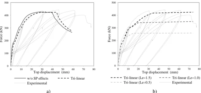
Once the cyclic response of the anchorage system is determined for the four different anchorage conditions considered, simplified tri-linear moment-rotation relationships were adjusted to the numerical results (Figure 5). As noted before, these relations are to be assigned to zero-length elements that, in turn, will be defined at the base of the wall element. These new models, defined in OpenSees, were submitted to nonlinear static (pushover) analysis in order to evaluate the changes in the global behaviour resulting from the consideration of the SP effects with different anchorage conditions. The results obtained, expressed in terms of base shear-top displacement, are presented in Figure 6.
The results presented in the following figure show that the consideration of the SP leads to an increase of the overall flexibility of the walls. This effect can be noted in a softer capacity curve of the models with SP effects with respect to the one with fixed base conditions. Furthermore, in the models featuring smooth rebars with reduced embedment length (i.e., Le=1.0 m and Le=0.5 m), the RC wall present also a reduction in the shear strength, as the
embedment length of the rebars decreases.
a) b)
Figure 6: Shear force-top displacement relation for ribbed (a) and smooth rebars with different embedment length (b) for the RC wall specimen WSH4.
0 100 200 300 400 500 0 10 20 30 40 50 60 70 80 F o rc e (k N ) Top displacement (mm) w/o SP effects Tri-linear Experimental 0 100 200 300 400 500 0 10 20 30 40 50 60 70 80 F o rc e (k N ) Top displacement (mm)
Tri-linear (Le=1.5) Tri-linear (Le=1.0) Tri-linear (Le=0.5) Experimental
With respect to the previous figure, it should be noted that, despite the strength of the anchorage system with smooth rebars and Le=1.5 m is lower than the one with ribbed rebars with the same anchorage length (see Figure 5), its strength is still sufficiently large to sustain the maximum lateral strength that the wall can develop. For this reason, the maximum shear force in the wall is very similar for both cases.
4.2 Calibration of reinforcement properties to account for SP effects
The results presented in the previous section demonstrate the importance of incorporating the SP effects in seismic analyses, particularly for structures with smooth rebars. Considering the limitations in the numerical models available to simulate these effects, this section presents the results of a calibration procedure carried out to establish reference reduction values for the Young’s Modulus and the maximum stress of the reinforcing steel.
In order to estimate the reduction of the rebar’s capacity, a constant averaged bond stress is considered along the total anchorage length. Taking in consideration the geometrical characteristic of the rebars (the area As and the perimeter P) and the maximum constant
averaged bond stress τmax, it is possible to evaluate the maximum steel strength fs developed
for different embedment lengths, through equilibrium considerations between the force in the rebar Fy,max and the anchorage force Fa:
τ (5, 6)
The value of τmax considered follows the one adopted in the Model Code 2010 (fib, 2011),
for the case of smooth rebars:
τ (7)
where fcm is the mean value of the concrete compressive strength in MPa.
The application of this procedure leads to reductions of Fy,max that ranged from 0 to 60% of
the expected rebar strength. These values are summarized in Table 3, together with the values of the reduction of the Young Modulus obtained for all cases.
Applying a rotational spring at the anchorage region of the RC walls conducted to a reduction on the Young Modulus of the steel material of the rebars of approximately 20% for ribbed rebars and 40% for smooth rebars.
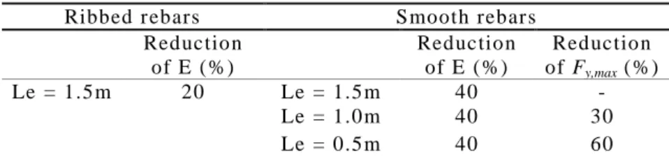
Table 3: Summary of the percentage reduction for the Young modulus (E) and the maximum strength (Fy,max) of the reinforcing steel.
Ribbed rebars Smooth rebars
Reduction of E (%) Reduction of E (%) Reduction of Fy,max (%) Le = 1.5m 20 Le = 1.5m 40 - Le = 1.0m 40 30 Le = 0.5m 40 60
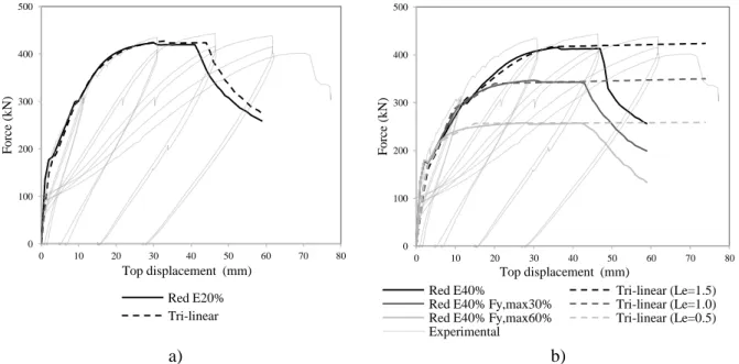
The appropriateness of these values was determined through the comparison of the correspondent numerical response against benchmark numerical outcomes obtained with the model in [22], as illustrated in Figure 7. The results show that the response of the model with the calibrated parameters is in line with the one obtained considering a rotational spring with a tri-linear relation. Nonetheless, the responses in the post-peak branch present some important differences. This is essentially because the model with the tri-linear rotational spring accounts
for the SP deformations throughout the entire response of the wall, i.e., both at the linear and nonlinear regime, whilst the reduction in the Young Modulus increases the wall flexibility only up to yielding of the rebars. This effect can be appraised in the larger lateral displacement of the wall when the strength decreases abruptly (Figure 7, a). In the presence of smooth rebars (Figure 7, b), the anchorage system becomes even more flexible, reducing the loading demand in the wall for the same level of lateral top displacement, precluding the wall to reach its maximum lateral strength. In these cases, the wall will eventually fail due to failure of the anchorage system.
a) b)
Figure 7: Comparison of the shear force-top displacement relation for ribbed (a) and smooth rebars with different embedment length (b), considering the model with reinforcement parameters calibrated
and the one considering a rotational spring with a tri-linear relation.
5 CONCLUSION
This work presents a numerical study addressing the behaviour of slender RC walls, in particular, the importance of strain penetration effects in the seismic behaviour of these elements. For this purpose, a slender RC wall experimentally tested in the past was used as benchmark for which different anchorage conditions were considered.
The quantification of the SP effects was firstly determined with an explicit bond-slip model capable of accounting for different properties of the anchorage region. Once the moment-rotation relationships were determined for different rebar properties (ribbed and smooth) and anchorage lengths, these relations were incorporated through zero-length elements at the base of the model of the wall.
The results of the pushover analyses carried out showed that the consideration of the SP effects introduces a non-negligible flexibility at the base of the wall that becomes more relevant as the anchorage conditions deteriorate, namely with the consideration of smooth rebars and reduced anchorage lengths. Moreover, when in presence of reduced embedment lengths, the lateral strength of the wall can be significantly compromised due to failure of the anchorage system.
Despite being limited to a single wall specimen, the results allowed to define indicative values that can be used to reduce the Young Modulus and the maximum strength of the rebars in order to implicitly account for such effects in numerical analyses in a very expedite
0 100 200 300 400 500 0 10 20 30 40 50 60 70 80 F o rc e (k N ) Top displacement (mm) Red E20% Tri-linear 0 100 200 300 400 500 0 10 20 30 40 50 60 70 80 F o rc e (k N ) Top displacement (mm)
Red E40% Tri-linear (Le=1.5) Red E40% Fy,max30% Tri-linear (Le=1.0) Red E40% Fy,max60% Tri-linear (Le=0.5) Experimental
manner. Hence, it was observed that, for ribbed rebars with appropriate embedment length, the reduction in the Young Modulus should be in the order of 20%, whilst in the presence of smooth rebars, this value should increase to values in the order of 40%, regardless of the embedment length. In what regards the rebars strength, this value is naturally dependent on the embedment length, and may need to be reduced to values in the order of 60% of its expected value. Appropriate general expressions to estimate this parameter for different anchorage lengths were presented in this paper. In the future, the authors intend to extend the present study to a larger number of RC walls with different properties in order to establish more general reference values for its parameters.
REFERENCES
[1] Sezen H. and Moehle J., “Strength and Deformation Capacity of Reinforced Concrete Columns with Limited Ductility”, Proceedings of 13th
World Conference on Earthquake Engineering,
Vancouver, Canada, 2004.
[2] Goodnight J. C., Feng Y., Kowalsky M. J. and Nau J. M., "The Effects of Load History and Design Variables on Performance Limit States of Circular Bridge Columns – Volume 1",
Technical Report, Alaska Department of Transportation and Public Facilities, USA, 2015b.
[3] Verderame G. M., Fabbrocino G. and Manfredi G., “Seismic response of r.c. columns with smooth reinforcement. Part I: Monotonic tests”, Engineering Structures, 30 (9), 2277-2288, 2008. [4] Melo J., Fernandes C., Varum H., Rodrigues H., Costa A. and Arêde A., “Numerical modelling of the cyclic behaviour of RC elements built with plain reinforcing bars”, Engineering Structures, 33 (2), 273-286, 2011.
[5] Dazio A., Beyer K. and Bachmann H., “Quasi-static cyclic tests and plastic hinge analysis of RC structural walls”, Engineering Structures, 31 (7), 1556-1571, 2009.
[6] Paulay T., Priestley M.J.N., “Seismic Design of Reinforced Concrete and Masonry Buildings”,
John Wiley & Sons, Inc., New York, 1992.
[7] Beyer K., Dazio A. and Priestley M.J.N., “Shear deformations of slender reinforced concrete walls under seismic loading”, ACI Structural Journal, 108 (2), 167 – 177, 2011.
[8] Priestley M.J.N., Calvi G.M. and Kowalsky M.J., “Direct displacement-based seismic design of structures”, IUSS Press, Pavia, 2007.
[9] Sritharan, S, Priestley, N, and Seible, F, "Nonlinear finite element analyses of concrete bridge joint systems subjected to seismic actions", Finite Elements in Analysis and Design, Vol. 36, No.3-4, pp. 215–233, 2000.
[10] Wu Y. and Lan T., “Macro-modelling of reinforced concrete structural walls: state-of-the-art”,
Journal of Earthquake Engineering, 2016.
[11] Almeida J., Tarquini D. and Beyer K., “Modelling approaches for inelastic behaviour of RC walls: multi-level assessment and dependability of results”, Archive of Computational Methods in
Engineering, 2014.
[12] Sousa R., “Development and Verification of Innovative Modelling Approaches for the Analysis of Framed Structures Subjected to Earthquake Action”, PhD thesis, UME School, IUSS Pavia, Pavia, Italy, 2015.
[13] Filippou F., Popov E. and Bertero V., "Effects of Bond Deterioration on Hysteretic Behaviour of Reinforced Concrete Joints", Report No. UCB/EERC-83/19, Earthquake Engineering Research Center, University of California, Berkeley, USA, 1983.
[14] Popov E., “Bond and Anchorage of Reinforcing Bars Under Cyclic Loading”, ACI Journal, 81 (4), 340–349, 1984.
[15] Lowes L., “Finite Element Modeling of Reinforced Concrete Beam-Column Bridge Connections”, PhD Thesis, University of California, Berkeley, USA, 1999.
[16] Salem H. and Maekawa, K., “Pre- and Postyield Finite Element Method Simulation of Bond of Ribbed Reinforcing Bars”, Journal of Structural Engineering, 130 (4), 671–680, 2004.
[17] Jendele L. and Cervenka J., “Finite element modelling of reinforcement with bond”, Computers
& Structures, 84 (28), 1780–1791, 2006.
[18] Casanova A., Jason L. and Davenne L., “Bond slip model for the simulation of reinforced concrete structures”, Engineering Structures, 39, 66–78, 2012.
[19] Mendes L. and Castro L., “A new RC bond model suitable for three-dimensional cyclic analyses”, Computers & Structures, 120, 47–64, 2013.
[20] Zhao J., Sritharan S., Modeling of Strain Penetration Effects in Fiber-Based Analysis of Reinforced Concrete Structures, ACI Structural Journal, 104 (2), 133–141, 2007.
[21] Monti G., Filippou F. and Spacone E., “Finite Element for Anchored Bars under Cyclic Load Reversals”, Journal of Structural Engineering, 123 (5), 614–623, 1997.
[22] Sousa R., Correia A. A., Almeida J. P. and Pinho R., “A fibre-based frame element with explicit consideration of bond-slip effects”, Proceedings of the 16th World Conference on Earthquake,
Santiago, Chile, (9-13/01), 2017.
[23] Sousa R., Correia A.A., Almeida J.P. and Pinho R., “Blind prediction tests as a benchmark to improve the seismic response of fibre models”, 2nd
European Conference on Earthquake Engineering and Seismology, Istanbul, Turkey, 2014.
[24] Varum H., “Seismic assessment, strengthening and repair of existing buildings”, PhD Thesis, Civil Engineering Department, University of Aveiro, Portugal, 2003.
[25] Fernandes C., Varum H. and Costa A., “Concrete-steel bond characterization of RC structural elements built with smooth plain reinforcement bars”, 2nd
Symposium “Connections between Steel and Concrete, 2007.
[26] McKenna F., Fenves G.L., Scott H.M. and Jeremic. B., “Open system for earthquake engineering simulation (OpenSEES)”, Pacific Earthquake Engineering Research Center, University of California, CA, 2000.
[27] Neuenhofer A. and Filippou F.C., “Evaluation of nonlinear frame finite-element models”, Journal
of Structural Engineering, 123 (7), 958–966, 1997.
[28] Menegotto M. and Pinto P.E., “Method of analysis for cyclically loaded RC plane frames including changes in geometry and non-elastic behaviour of elements under combined normal force and bending”, IABSE Symposium on resistance and ultimate deformability of structures
acted on by well defined repeated loads—Final Report, 1973.
[29] Popovics S., “A numerical approach to the complete stress–strain curve of concrete”, Cement and
concrete research, 3 (5), 583–599, 1973.
[30] Mander J.B., Priestley M.J.N., Park R, "Theoretical stress–strain model for confined concrete",
Journal of Structural Engineering , 114 (8), 1804–1826, 1988.
[31] Calabrese A., Almeida J.P., Pinho R., “Numerical issues in distributed inelasticity modeling of RC frame elements for seismic analysis”, Journal of Engineering, 14 (S1), 38–68, 2010.
[32] fib (2011). Model Code 2010. International Federation for Structural Concrete, Lausanne, Switzerland.
![Figure 1: Behaviour of anchorage region with adequate (left) and limited (right) embedment length (adapted from [20])](https://thumb-eu.123doks.com/thumbv2/123dok_br/18586846.908473/3.892.192.732.625.751/figure-behaviour-anchorage-region-adequate-limited-embedment-adapted.webp)
![Figure 2: Correction of the steel reinforcing law (adapted from [24]).](https://thumb-eu.123doks.com/thumbv2/123dok_br/18586846.908473/4.892.327.564.510.696/figure-correction-steel-reinforcing-law-adapted.webp)