Micael Moreira Alves
Influence of lens care solutions on transmittance
and reflectance of contact lenses
19
Micael Mor
eir
a Alv
es
Influence of lens care solutions on transmitt
ance and reflect
ance of cont
act lenses
Universidade do Minho
Escola de Ciências
Dissertação de Mestrado
em Optometria Avançada
Trabalho efetuado sob a orientação de
Professora Doutora Maria Madalena da Cunha Faria de Lira
Professora Doutora Elisabete M. S. Castanheira Coutinho
Universidade do Minho
Escola de Ciências
Micael Moreira Alves
Influence of lens care solutions on transmittance
and reflectance of contact lenses
DECLARAÇÃO
Nome: Micael Moreira Alves
Endereço eletrónico: micaelmalves22@gmail.com
Bilhete de Cartão do Cidadão: 14101085 1 ZY2
Título da dissertação: Influência das soluções de manutenção na transmitância e refletância das lentes de contacto
Orientadores:
Professora Doutora Maria Madalena da Cunha Faria de Lira
Professora Doutora Elisabete Maria dos Santos Castanheira Coutinho
Ano de conclusão: 2019
Designação do Mestrado: Optometria Avançada
DE ACORDO COM A LEGISLAÇÃO EM VIGOR, NÃO É PERMITIDA A REPRODUÇÃO DE QUALQUER PARTE DESTA TESE.
Universidade do Minho, _____/_____/_________
A
CKNOWLEDGMENTS
No seguimento da presente dissertação, o contributo direto e indireto de pessoas e instituições foram imprescindíveis, às quais presto o meu absoluto reconhecimento. Desta forma e correndo o risco de não mencionar algum dos colaborantes quero expressar os meus respeitáveis agradecimentos:
À minha família, em particular aos meus pais, à minha irmã e à minha tia Manuela Alves pelos valores éticos e morais que me transmitiram. Também à minha avó Rosalina Moreira, dotada de uma honrosa sabedoria.
A todos os colegas e amigos que fizeram parte do meu percurso de vida privada, académico e profissional, nomeadamente ao Sérgio Silva, Ana Catarina Fernandes e Marisa Ferreira por terem sido um apoio substancial em todos os campos.
A todo o corpo docente, pela partilha de conhecimento e experiências, em especial à minha orientadora Professora Doutora Madalena Lira e coorientadora Professora Doutora Elisabete Coutinho por toda a disponibilidade e prontidão que demonstraram no desenvolvimento deste projeto. À doutoranda Rita Rodrigues pelo incansável apoio no contexto experimental. Aos Professores Doutores António Macedo e Ana Maria Pinho pelo incentivo e palavras de força em momentos mais difíceis.
À instituição Universidade do Minho, nomeadamente à Escola de Ciências, ao corpo do mestrado em Optometria Avançada que é tão bem dirigido pelo Professor Doutor João Linhares e aos serviços de documentação, particularemente aos funcionários da biblioteca geral. Às empresas de contactologia que elogiavelmente cooperam com o departamento de Optometria e Ciências da Visão, facultando o material indispensável para este projeto.
Às mentes vivas que contribuem e impulcionam ativamente a ciência procurando respostas fundamentadas para as suas questões.
Bem hajam pelo vosso contributo. Grato pela vossa colaboração. A todos o meu sincero Muito Obrigado!
A
BSTRACT
Influence of Lens Care Solutions on transmittance
and reflectance of contact lenses
Relevance: The transmittance is an optical property of contact lenses (CLs) that represents the amount of refracted light. This attribute displays interest in issues related to protection against ultraviolet radiation (UVR) and visual performance of lenses. Currently, epidemiological and experimental evidence exists for the role of UVR phototoxicity in pathological changes to the ocular tissues. When placed in solutions, previous studies have shown that some combinations result in significant changes in the CLs properties, including in the optical domain.
Purpose: To investigate the effects of four lens care solutions on transmittance and reflectance of five contact lenses materials, analyzing the lenses before and after storage.
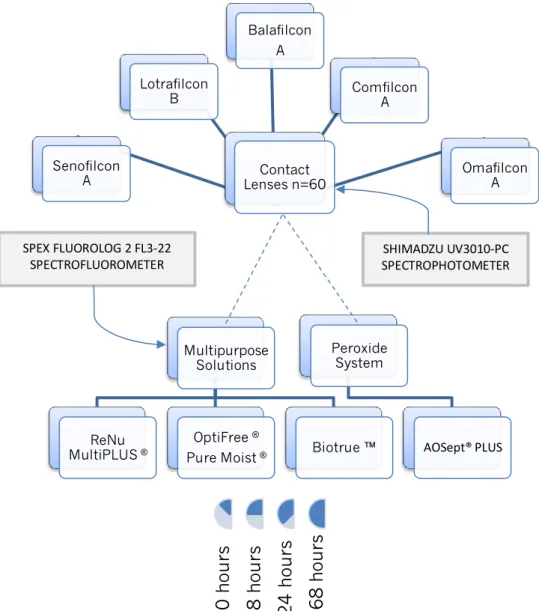
Methods: From a cohort study, triplicate measurements of tansmittance and reflectance of CLs was evaluated after 8 hours, 1 day and 1 week of storage with three
multi-purpose solutions (MPSs: ReNu MultiPlus® MPS, Biotrue™ and Optifree® PureMoist®) and one
hydrogen peroxide system (AOSept® Plus). The lenses used in this study were Acuvue Oasys™,
Air Optix Aqua™, Purevision® 2, Biofinity™ and one conventional hydrogel material, Proclear™. The outcomes were provided by Shimadzu UV3101-PC UV-vis-NIR spectrophotometer equipped with an integrating sphere, between 200-700 nm. The fluorescence variables of solutions were performed by SPEX-Fluorolog 2 FL3-22 spectrofluorometer to assess the effects of materials in the products.
Results: After immersed in the different solutions, all the materials exhibited a greater or lesser statistically significant differences on study variables over time. The Comfilcon A showed the lowest UVA & UVB attenuation. Balafilcon A and Lotrafilcon B displayed a considerable suppression of UV radiation. Senofilcon A was effective in UVR protection and showed less effect on the fluorescence of liquids. Overall, the reflectance decreased after storage. In the LCSs, the outcomes of AOSept absorbance and fluorescence demonstrated lower affection in relation to MPSs solutions and Lotrafilcon B displayed greater changes in all study variables compared with the other materials.
Conclusion: Significant differences on transmittance were found after storage, probably due to the intractions with the products. AOSept showed greater strength to CLs effect compared with MPSs. The changes exhibited in the visible spectrum have no implications on visual performance.
R
ESUMO
Influência das soluções de manutenção na transmitância
e refletância das lentes de contacto
Relevância: A transmitância é uma propriedade ótica das lentes de contato que representa a quantidade de luz refratada. Este atributo apresenta interesse em questões relacionadas com a proteção contra a radiação ultravioleta (UVR) e com o desempenho visual das lentes. Atualmente, existem evidências epidemiológicas e experimentais para o papel da fototoxicidade da UVR nas alterações patológicas dos tecidos oculares. Quando colocadas em soluções de manuntenção, estudos anteriores mostraram que algumas combinações resultam em mudanças significativas nas propriedades das lentes de contacto, inclusive no domínio óptico.
Objetivo: Investigar os efeitos de quatro soluções de manutenção de lentes na transmitância e refletância de cinco materiais de lentes de contato, analisando as lentes antes e depois de armazenadas.
Métodos: A partir de um estudo coorte, medidas triplicadas de tansmitância e refletância de lentes foram avaliadas depois de 8 horas, 1 dia e 1 semana de armazenamento com três soluções únicas (ReNu MultiPlus® MPS, Biotrue ™ e Optifree® PureMoist®) e um sistema de peróxido de hidrogênio (AOSept® Plus). As lentes usadas neste estudo foram Acuvue Oasys ™, Air Optix Aqua ™, Purevision® 2, Biofinity ™ e um material de hidrogel convencional, Proclear ™. Os resultados foram obtidos pelo espectrofotómetro Shimadzu UV3101-PC UV-vis-NIR equipado com esfera integradora, entre 200 - 700 nm. A variável de fluorescência das soluções foi obtida pelo espectrofluorímetro SPEX-Fluorolog 2 para avaliar os efeitos dos materiais nos produtos.
Resultados: Após imersos nas diferentes soluções, todos os materiais apresentaram diferenças estatisticamente significativas das variáveis de estudo ao longo do tempo. Comfilcon A mostrou a mais baixa atenuação de UVA & UVB. Balafilcon A e Lotrafilcon B exibiram uma considerável supressão da radiação UV. Senofilcon A foi efetivo na proteção da radiação UV e mostrou menor efeito na fluorescência dos produtos. No geral, a refletância
diminuiu após armazenamento. Os resultados da absorvância e fluorescência do AOSept
demonstraram menor comprometimento em relação às soluções únicas e o Lotrafilcon B mostrou maiores alterações em todas as variáveis de estudo comparado com os outros materiais.
Conclusão: Diferenças significativas na transmitância foram encontradas após o armazenamento, provavelmente devido às interações com os produtos. O AOSept mostrou maior resistência ao efeito das lentes comparado com as soluções únicas. As alterações exibidas no espectro visível não têm implicações no desempenho visual.
I
NDEX
Acknowledgments ... i
Abstract ...ii
Resumo ... iii
Index ... iv
Index of figures ... vii
Index of tables ... xii
Index of equations ... xv
Glossary of terms, abbreviations and acronyms ... xvi
1. Introduction ... 1
2. Objectives and hypothesis of the study ... 2
2.1. Statement of the research problem ... 2
2.2. Objectives ... 2
2.3. Hypothesis formulation ... 3
1st Part Literature review ... 4
3. Vision optics ... 5
3.1. Vision optics - basic concepts about the eye and refractive errors ... 5
3.2.Vision optics - optical radiation and ocular implications ... 6
4. Contact Lenses ... 10
4.1.Historical background and overall trends ... 10
4.2. Contact lenses – manufacturing techniques and designs ... 13
4.2.1. Manufacturing techniques ... 13
4.2.2. Specific designs ... 15
4.3. Contact lenses materials – main properties ... 16
4.3.1. Optical properties – Refractive Index (RI) ... 16
4.3.2. Optical properties – Transmittance, Reflectance and Absorbance ... 17
Transmittance of UV-visible radiation in contact lenses – a hot topic ... 18
4.3.6. Surface properties - wettability... 24
4.3.7. Mechanical properties - Young´s modulus (YM) and hardness ... 25
5. Lens care solutions ... 26
5.1. Lens care solutions - background and overview ... 26
5.2. Soft lens care solutions – components and functions ... 27
5.2.1. Cleaning agents (surfactant) ... 27
5.2.2. Preservatives and disinfectants products ... 28
5.2.3. Buffer solution ... 29
5.2.4. Wetting and lubrification agents ... 29
5.2.5. Chelating agents ... 29
5.3. Hydrogen peroxide (H2O2) – chemical disinfection by oxidation ... 29
5.4. Soft contact lenses and products - clinical implications ... 30
Influence of wear and storage in UV-visible transmittance of SiHy CLs ... 32
6. Fundamentals of absorbance and fluorescence ... 34
2nd Part Study development ... 37
7. Methodology ... 38
7.1. Study design – ethics in research ... 38
7.2. Sample size – selection and inclusion criteria ... 38
7.3. Sample characterization ... 38
7.3.1. Contact lenses ... 38
7.3.2. Lens care solutions ... 40
7.4. Experimental procedure ... 41
7.5. Transmittance and reflectance measurements ... 41
7.6. Absorbance and fluorescence measurements ... 44
7.7. Statistical analysis ... 46
8. Results and discussion ... 47
8.1. Effect of lens care solutions on transmittance and reflectance of CLs ... 47
8.1.1. Analysis of the UV-visible transmittance ... 47
Approach of the UV radiation (240-400 nm) ... 57
8.1.3. Overall analysis of transmittance and reflectance ... 70
8.2. Influence of CLs on absorbance and fluorescence properties of LCSs ... 74
8.2.1. Analysis of the UV-visible absorbance of lens care solutions ... 74
8.2.2. Analysis of the UV-visible fluorescence of lens care solutions ... 83
8.3. Overall analysis with clinical associations ... 95
9. Conclusion and future work ... 97
I
NDEX OF FIGURES
Chapter 3 - Visual optics Figure 3.1. Focal points in myopia and hyperopia. (I) In myopia, the image of a point at infinity is projected in front of the retina; (II) In hyperopia, the image is projected behind the retina (Reproduced from Kohnen et al.,2008). ...6 Figure 3.2. Optical radiation of electromagnetic spectrum: UV (100-400 nm), visible (400-760 nm), and infrared (760-10 000 nm)(Reproduced from Bloomfiel, 2005). ...7 Figure 3.3. Schematic diagram of a cross section eye showing relative propagation of optical radiation through the ocular tissues. UVC and UVB do not propagate past the cornea and the lens, respectively. IRB and IRC are absorbed by the cornea. Respectively, less than 2% and 1% of UVA and UVB radiation reaches the retina. (1) cornea, (2) crystalline lens, (3) retina (Reproduced from Ivanov et al.,2018). ...8
Chapter 4 - Contact lenses Figure 4.1. Schematic representation of key aspects of contact lens material development (Reproduced from Bhamra TS, 2016). ...11 Figure 4.2. Major global trends in contact lens prescribing from 1997 to 2017 (Reproduced from Morgan PB et al, 2018). ...12 Figure 4.3. Schematic representation of the reflection and transmission light in a contact lens. (a) when a light beam with an initial intensity (I0), interact an optically denser material (ni < nt),
the transmitted light approaches the normal (N). (b) when the angle of incidence (Ɵi) is zero,
the transmitted light follow the normal axis (Adapted from Okuno et al., 1982)...18 Figure 4.4. Optical representation of peripheral light focusing. a) intense nasal light focus (pterygia implications); b) transcameral and translenticular passage of PLF (implications in early onset cortical lens opacity). Adapted from Coroneo M., 2011. ...20
Chapter 5 - Lens care solutions Figure 5.1. Care regimens prescribed in 2017 (Reproduced from Morgan PB et al, 2018). ....27
Chapter 6 – Fundamentals of absorbance and fluorescence Figure 6.1. Schematic representation of the processes during absorption of radiation beam by a solution. I0 represent the incident beam, Is represent the transmitted beam and b is the length of optical path in the sample (Adapted from Martinho, 1994). ...35 Figure 6.2. Jablonski diagram. An electron of a fluorophore at the ground state (S0) receives energy from the absorption of a single photon of light which results in excitation transition to a higher energy state (absorption). When the excited electron relaxes to the ground state, following vibrational losses, energy lower than the incident photon and thus with a higher wavelength, is emitted as a single photon causing fluorescence (Reproduced from Shashkova & Leake, 2017)...35
Chapter 7 - Methodology Figure 7.1. Schematic representation of the experimental methodology of this study. ...41 Figure 7.2. Shimadzu UV3101-PC UV-vis-NIR spectrophotometer...42 Figure 7.3. Tweezers with silicone tips and support system designed to CLs. ...42 Figure 7.4. Schematic representation of reflectance measurements (Adapted from the user manual of the equipment). ...43 Figure 7.5. Schematic representation of transmittance measurement of CLs (Adapted by instruction manual). ...43 Figure 7.6. Sterile vial with 2 ml of lens care solution and one contact lens. ...44 Figure 7.7. High precision quartz glass cell (10×10 mm). Dimensions: 45 × 12,5 × 12,5; volume: 3,5 ml (Hellma Analytics, Germany). ...44 Figure 7.8. Schematic representation of absorbance measurement of liquid samples. ...45 Figure 7.9. SPEX Fluorolog 2 spectrofluorometer. ...45
Chapter 8 - Results and discussion
Figure 8.1. Transmittance spectra (UV-visible range) for Acuvue® Oasys after opening (control) and after 8, 24 and 168 hours of storage in the lens care solutions. a) Renu; b) OptiFree; c) Biotrue and d) AOSept. ...49
Figure 8.2. Transmittance spectra (UV-visible range) for AirOptix® Aqua after opening (control) and after 8, 24 and 168 hours of storage in the lens care solutions. a) Renu; b) OptiFree; c) BioTrue and d) AOSept. ...52 Figure 8.3. Transmittance spectra (UV-visible range) for Purevision® 2 after opening (control) and after 8, 24 and 168 hours of storage in the lens care solutions. a) Renu; b) OptiFree; c) Biotrue and d) AOSept. ...52 Figure 8.4. Transmittance spectra (UV-visible range) for Biofinity™ after opening (control) and after 8, 24 and 168 hours of storage in the lens care solutions a) Renu; b) OptiFree; c) BioTrue and d) AOSept. ...54 Figure 8.5. Transmittance spectra (UV-visible range) for Proclear™ after opening (control) and after 8, 24 and 168 hours of storage in the lens care solutions. a) Renu; b) OptiFree; c) BioTrue and d) AOSept. ...56 Figure 8.6. Transmittance spectra (UV-visible range) for Acuvue®Oasys (AC), AirOptix® (AO), Purevision® 2 (PU), Biofinity™ (BI) and Proclear™ (PR) after opening (black) and after 8 hours of storage in Renu (orange), OptiFree (blue), BioTrue (green) and AOSept (red). ...56 Figure 8.7. Transmittance spectra (UV-visible range) for Acuvue Oasys® (AC), AirOptix® (AO), Purevision® 2 (PU), Biofinity™ (BI) and Proclear™ (PR) after opening (control) and after 1 week of storage in Renu (orange), OptiFree (blue), BioTrue (green) and AOSept (red). ...57 Figure 8.8. Reflectance spectra (UV-visible range) for Acuvue® Oasys after opening (control) and after 8, 24 and 168 hours of storage in the LCS. a) Renu; b) OptiFree; c) Biotrue and d) AoSept. ...63 Figure 8.9. Reflectance spectra (UV-visible range) for AirOptix® Aqua after opening (control) and after 8, 24 and 168 hours of storage in the LCSs. a) Renu; b) OptiFree; c) BioTrue and d) AOSept. ...63 Figure 8.10. Reflectance spectra (UV-visible range) for Purevision® 2 after opening (control) and after 8, 24 and 168 hours of storage in the LCS. a) Renu; b) OptiFree; c) Biotrue and d) AOSept. ...66 Figure 8.11. Reflectance spectra (UV-visible range) for Biofinity™ after opening (control) and after 8, 24 and 168 hours of storage in the LCS. a) Renu; b) OptiFree; c) Biotrue and d) AoSept. ...66
Figure 8.12. Reflectance spectra (UV-visible range) for Proclear™ after opening (control) and after 8, 24 and 168 hours of storage in the LCS. a) Renu; b) OptiFree; c) Biotrue and d) AoSept. ...68 Figure 8.13. Reflectance spectra (UV-visible range) for Acuvue® Oasys (AC), AirOptix® (AO), Purevision® 2 (PU), Biofinity™ (BI) and Proclear™ (PR) after opening (black) and after 8 hours of storage in the Renu (orange), OptiFree (blue), BioTrue (green) and AOSept (red). ...69 Figure 8.14. Mean transmittance of each CL material before (control in gray) and after 8 hours of storage in the Renu (orange), OptiFree (blue), BioTrue (green) and AOSept (red). ...71 Figure 8.15. Schematic representation of light scattering by micelles in solution. ...74 Figure 8.16. Absorbance spectra (UV-visible range) for ReNu MP® before (black) and after 8, 24 and 168 hours of storage with Acuvue Oasys (AC - orange), AirOptix (AO - blue), Purevision (PU - green), Biofinity (BI - red) and Proclear (PR - purple). ...78 Figure 8.17. Absorbance spectra (UV-visible range) for Opti-Free® PM® before (black) and after 8, 24 and 168 hours of storage with Acuvue Oasys (AC - orange), AirOptix (AO - blue), Purevision (PU - green), Biofinity (BI - red) and Proclear (PR - purple). ...78 Figure 8.18. Absorbance spectra (UV-visible range) for BioTrue™ before (black) and after 8, 24 and 168 hours of storage with Acuvue (AC - orange), AirOptix (AO - blue), Purevision (PU - green), Biofinity (BI - red) and Proclear (PR - purple). ...82 Figure 8.19. Absorbance spectra (UV-visible range) for AoSept® Plus before (black) and after 8, 24 and 168 hours of storage with Acuvue (AC - orange), AirOptix (AO - blue), Purevision (PU - green), Biofinity (BI - red) and Proclear (PR - purple). ...82 Figure 8.20. Fluorescence spectra (UV-visible range) for ReNu MP® before (control) and after 8, 24 and 168 hours of storage with the CLs. a) Acuvue; b) AirOptix; c) Purevision; d) Biofinity and e) Proclear. The above spectra (´) represent excitation at 280 nm and below spectra represent the excitation at 350 nm...85 Figure 8.21. Fluorescence spectra (UV-visible range) for Opti-Free® PM® before (full lines) and after 8, 24 and 168 hours of storage with the CLs. a) Acuvue; b) AirOptix; c) Purevision; d) Biofinity and e) Proclear. The above spectra (´) represent excitation of 280 nm and below spectra represent the excitation of 350 nm. ...87 Figure 8.22.Fluorescence spectra (UV-visible range) for BioTrue™ before (full lines) and after 8, 24 and 168 hours of storage with the tested CLs. a) Acuvue; b) AirOptix; c) Purevision; d)
Biofinity and e) Proclear. The above spectra (´) represent excitation of 280 nm and below spectra represent the excitation of 350 nm. ...88 Figure 8.23. Fluorescence spectra (UV-visible range) for AOSept® Plus before (full lines) and after 8, 24 and 168 hours of storage with the tested CLs. a) Acuvue; b) AirOptix; c) Purevision; d) Biofinity and e) Proclear. The above spectra (´) represent excitation of 280 nm and below spectra represent the excitation of 350 nm. Zoom window shows 400 nm level. ...90 Figure 8.24. Fluorescence spectra (UV-visible range) for the excitation at 280 nm for Renu® (RE), OptiFree® (OF), BioTrue™ (BI) and AOSept® (AO) after opening (black) and after 8 hours of storage with Acuvue (orange), AirOptix (blue), Purevision (green), Biofinity (red) and Proclear (purple)...93 Figure 8.25. Fluorescence spectra (UV-visible range) for the excitation at 350 nm for Renu® (RE), OptiFree® (OF), BioTrue™ (BT) and AOSept® (AO) after opening (black) and after 8 hours of storage with Acuvue (orange), AirOptix (blue), Purevision (green), Biofinity (red) and Proclear (purple)...93
I
NDEX OF TABLES
Chapter 4 - Contact lenses
Table 4.1. Some exemples of hydrogel materials (Reproduced from Weissman BA et al., 2006). ...13 Table 4.2. Summary of results of 21st century studies about UV protection of reusable CLs.. ...20
Chapter 5 - Lens care solutions
Table 5.1. Physical properties of three research solutions (Adapted from Dalton et al.,2008). ...31
Chapter 7 - Methodology Table 7.1. Properties and parameters of the contact lenses used in this study. ...39 Table 7.2. Principal components of soft contact lens solutions investigated. ...40
Chapter 8 – Results and discussion Table 8.1. Mean transmittance values of Acuvue® Oasys before (control) and after storage in the different LCSs, results of Kruskal-Wallis 1-way ANOVA and Friedman ANOVA. ...48 Table 8.2. Mean transmittance values of AirOptix® Aqua before (control) and after storage in the different LCSs, results of Kruskal-Wallis 1-way ANOVA and Friedman ANOVA. ...50 Table 8.3. Mean transmittance values of PureVision®2 before (control) and after storage in the different LCSs, results of Kruskal-Wallis 1-way ANOVA and Friedman ANOVA. ...51 Table 8.4. Mean transmittance values of Biofinity™ before (control) and after storage in the different LCSs, results of Kruskal-Wallis 1-way ANOVA and Friedman ANOVA. ...53 Table 8.5. Mean transmittance values of Proclear™ before (control) and after storage in the different LCSs, results of Kruskal-Wallis 1-way ANOVA and Friedman ANOVA. ...55 Table 8.6. Mean transmittance values (%) and protection factor between parentheses for UVA&UVB spectrum after 8 hours for all the combinations. ...58
Table 8.7. Mean transmittance values (%) for visible spectrum after 8 hours for all the combinations. ...59 Table 8.8. Mean reflectance values of Acuvue® Oasys before (control) and after storage in the different LCSs, results of Kruskal-Wallis 1-way ANOVA and Friedman ANOVA. ...61 Table 8.9. Mean reflectance values of Air Optix® Aqua before (control) and after storage in the different LCSs, results of Kruskal-Wallis 1-way ANOVA and Friedman ANOVA. ...62 Table 8.10. Mean reflectance values of PureVision®2 before (control) and after storage in the different LCSs, results of Kruskal-Wallis 1-way ANOVA and Friedman ANOVA. ...64 Table 8.11. Mean reflectance values of Biofinity™ before (control) and after storage in the different LCSs, results of Kruskal-Wallis 1-way ANOVA and Friedman ANOVA. ...65 Table 8.12. Mean reflectance values of Proclear™ before (control) and after storage in the different LCSs, results of Kruskal-Wallis 1-way ANOVA and Friedman ANOVA. ...67 Table 8.13. Mean of CLs variables (%) after 8 hours under the mean influence of products in UV-visible spectrum. The fraction of absorbed radiation (A) was obtained according to equation 4 (Rλ+ Tλ+ Aλ= 1). ...70 Table 8.14. Mean absorbance values of ReNu MP® before (control) and after storage with the different CLs, results of Kruskal-Wallis 1-way ANOVA and Friedman ANOVA. ...76 Table 8.15. Mean absorbance values of Opti-Free® PM® before (control) and after storage with the different CLs, results of Kruskal-Wallis 1-way ANOVA and Friedman ANOVA. ...77 Table 8.16. Mean absorbance values of BioTrue™ before (control) and after storage with the different CLs, results of Kruskal-Wallis 1-way ANOVA and Friedman ANOVA. ...80 Table 8.17. Mean absorbance values of AoSept® Plus before (control) and after storage with the different CLs, results of Kruskal-Wallis 1-way ANOVA and Friedman ANOVA. ...81 Table 8.18. Mean fluorescence intensity values for the excitation at 280 nm and 350 nm for ReNu® before (control) and after storage with the different CLs, results of K-W and Friedman. ...84 Table 8.19. Mean fluorescence intensity values for the excitation at 280 nm and 350 nm for Opti-Free® before and after storage with the different CLs, results of K-W and Friedman. ...86 Table 8.20. Mean fluorescence intensity values for the excitation at 280 nm and 350 nm for BioTrue™ before and after storage with the different CLs, results of K-W and Friedman. ...89
Table 8.21. Mean fluorescence intensity values for the excitation at 280 nm and 350 nm AOSept® before(control) and after storage with the different CLs, results of K-W and Friedman. ...91 Table 8.22. Mean fluorescence intensity values (a.u.) for all the combinations of excitation at 280 nm after 8 hours. ...94 Table 8.23. Mean fluorescence intensity values (a.u.) for all the combinations of excitation at 350 nm after 8 hours. ...94
I
NDEX OF EQUATIONS
𝑛 = 𝑐 𝑣 (Equation 1) 𝑅λ= 𝐼r 𝐼o= (𝑛t−𝑛i)2 (𝑛t+𝑛i)2 or %𝑅λ= 𝐼r 𝐼o × 100 (Equation 2) 𝑇λ= 𝐼t 𝐼o= 4𝑛t𝑛i (𝑛t+𝑛i)2 or %𝑇λ= 𝐼t 𝐼o × 100 (Equation 3) 𝑅λ+ 𝑇λ+ 𝐴λ= 1 or %𝑅λ+ %𝑇λ+ %𝐴λ= 1 (Equation 4) 𝑃𝐹 = 1 𝑇λ (Equation 5) 𝐸 = ℎ𝑣 = ℎ𝑐 𝜆 (Equation 6) 𝐴λ= − log 10𝐼λ𝐼0=
ε
λ𝑏𝐶 Law of Lambert-Beer – (Equation 7)G
LOSSARY OF TERMS
,
ABBREVIATIONS AND ACRONYMS
AM Acid methacrylic
ANSI American National Standards Institute
a.u. arbitrary units
BB Blue blocking
BC Base curve radius
CA Contact angle
CHy Conventional hydrogel
CLs Contact lens(es)
CS Corneal straining
cm centimeters
D Diopter(s) of optical power;
d diffusion coefficient
Dk Oxigen permeability
Dk/t Oxigen transmissibility
DW Daily wear
EDTA Ethylenediamine tetraacetic acid
EW Extended wear
FDA Food and Drug Administration
FI Fluorescence intensity (a.u.)
GP Gas permeable
Hy Hydrogel
HA Hyaluronic acid
IR Infrared radiation
LCSs Lens care solution(s)
m meters
mm milimeters
MPSs Multipurpose solution(s)
nm nanometers
OS Oxidative stress
p p-value: stastistical significance
PF Protection factor
PHMB polyhexamethylene biguanide (or PAPB)
PLF Peripheral light focusing
PQ-1 Polyquatermium-1 (or Polyquad)
P-HEMA Polyhydroxyethylmethacrylate
SiHy Silicone hydrogel
SCL Soft contact lens
R Refletance, expressed in % ; sample correlation coefficient
RGP Rigid gas permeable
RI Refractive index
T Transmitance, expressed in %; thickness of individual CL
UV Ultraviolet
UVR Ultraviolet radiation
VA Visual acuity
WC Water content
YM Young´s modulus
1. I
NTRODUCTION
The industry estimates around 140 million of contact lens (CL) wearers world-wide. New and improved materials, designs and modalities have made CLs a practical choice acepted for most of patients. Despite this trend, some eye problems are reported due the properties of CL materials and lens care systems (LCSs) interactions. The spectral transmittance of CLs is particularly important for visual performance and ultraviolet (UV) blocking levels. The transparency characteristics are strongly dependent on the lens material and the protective effect can be correleted with the absorption and stability of the ultraviolet (UV) filter incorporated in the CL matrix. There are no earlier reported studies that evaluate if the transmittance (T) properties remain unchanged during differents CLs storage in differents solutions. In order to contribute to the understanding of the current concern about the transmission of invasive light through a CL and the impact of the products on the optical properties of CL materials, the present experimental research was designed. This study was carried out to measure the mutual effect of storage of soft CLs in lens care solutions in terms of light transmission.
The structure of this dissertation follows the Arezes guideline1, starting with an
introduction and research rationale presented in this 1st chapter. The 2nd chapter support
the statement of the problematic issue, the mains goals and hypothesis formulation. From
this point, the investigation is divided in two parts. The 1st corresponds to the systematic
review of the literature that begins by presenting general concepts about the vision and visual implications of optical radiation, in 3rd chapter. The 4th and 5th chapters provides backgrounds, overviews, trends, clinical implications and main properties of CL and LCS, respectively, with emphasis for the transmittance of the lenses. The 6th disclose the
fundamentals of absorbance and fluorescence. The work developed is structured in 2nd
part, including the 7th chapter that adopts a methodological perspective with study design,
sample characterization, experimental procedure, instrumentation and statistical analysis
applied. The presentation of the results is detailed in the 8th chapter with the respective
2. O
BJECTIVES AND HYPOTHESIS OF THE STUDY
2.1
Statement of the research problem
Optical properties of CLs are important for wearers, not only in protection context of UVR but also in visual performance.
Experimental observations confirmed that the transmittance values of UV-visible light in Balafilcon A material exhibit statistically significant differences after storage in different multipurpose solutions (MPSs). The deterioration process of CLs affects their intrinsic physical properties and this process can induce a loss of quality of LCSs. The opposite can also be true. There was no evidence about the changes on optical properities of LCSs what could explain this investigation. If there is a relationship between the lens polymer and the contamination of the LCS or vice versa, we can understand problems associated with the use of reusable lenses. Previous in vivo studies have demonstrated the influence of wear on transmittance of soft contact lenses (SCLs) and the authors considered that biofilm formation was associated with the observed changes. The choice of CLs, LCS and the range of spectrum evaluated in this study were chosen to complement and update previous studies about transmittance and reflectance.
Research Question: “Do the lens care solutions influence the transmittance and refletance of contact lenses?”
2.2
Objectives
The main aim of this dissertation is to investigate the influence of lens care solutions in UV-visible spectrum transmittance and refletance of SCL over time.
The specific goals of the study are:
1. Understand liquid-lens interactions; 2. Analyse changes in LCS caused by CLs;
2.3
Hypothesis formulation
The hypotheses of this investigation are:
1. The transmittance and reflectance of CLs are not independent of the type of LCS selected;
2. There are not statistically significant differences in the refletance and transmittance of CLs over time after storage in LCSs;
3. The absorbance and fluorescence of LCS are not independent of the material type of CLs selected;
4. There are not statistically significant differences in the absorbance and fluorescence of the LCSs over time after storage with CLs.
1
ST
P
ART
L
ITERATURE REVIEW
This part gives a systematic review of the literature. It starts with general information about the visual system, addressing some visual implications associated with the radiation and then, provides the fundamental background and overviews about contact lenses and lens care solutions, reporting the main properties and also some epidemiologic issues. Studies about the influence of products on the contact lenses properties are described with greater emphasis, especially for the transmittance and reflectance.
3. V
ISION OPTICS
3.1
Vision optics - basic concepts about the eye and refractive errors
The visual perception is one of the most complex abilities of the human body that allows the perception of shape, size, colors, movement and position of objects. The eye or eyeball has the ability to focus and transform the electromagnetic radiation in nerve impulses.2
This structure is an adjustable lens system consisting of two focusing elements, the cornea and the lens, and a light receptor system, the retina. The cornea is the main focusing element. This transparent layer presents the greatest deflection due to its convexity. The aperture system iris-pupil depends on the intensity of the light and regulate its input. After crossing this “diaphragm”, the light ray is subjected to a second deflection by a variable focusing system. The lens or crystalline lens is a flexible and fibrous structure suspended by ciliary muscles. When the eye focuses an object at short distances, the muscles relax and the
lens is compressed, increasing its power. This process is known as accommodation.3 Finally,
the rays are focused and received on the retina which has a layer of photosensitive cells. The fovea is the central part of this receptor system responsible for clearer and more detailed information. The eye contains two types of photoreceptor cells: cones and rods. Rods are remarkably sensitive structures; however, they are unable to discriminate colors. In turn, the cones work with higher luminous intensities and there are three types of this cells: S (short wavelength), M (medium wavelength) and L (long wavelength), respectively sensitive to blue, green and red (figure 3.2). The focal points are dependent of the wavelength and located
within the long axis of the folded membrane in the segment of the retina.4 The nerve impulses
resulting from photoelectric stimuli are transported to the brain along the optic nerve. The most common types of refractive errors are myopia, hyperopia and astigmatism. Refractive errors are measured in diopters (D) and usually can be corrected by lenses in order to correctly focus the light on the retina.
Roughly, myopia is related to a long axial length of the eye and hyperopia with a short length. In myopia, the focuses are formed in front of the retina, resulting in a blurred image (figure 1.2, I) and compensation is made by a concave lens.
On the other hand, in hyperopia the light is focused behind the retina and the image is likewise blurred (figure 1.2, II). In this situation, the error is compensated by a convex lens.5
The astigmatism is maybe the most frequent defect of vision result of the curvature difference between two meridians of the cornea-lens system, resulting in a displaced or distorted image.3 If the planes of curvature are perpendicular, astigmatism is regular and possible to correct; otherwise is irregular and difficult to correct.
In last, presbyopia represents the difficulty in the near vision by normal loss of elasticity of the lens with aging.3,5
3.2.
Vision optics - optical radiation and ocular implications
The process of color discrimination of an object is promoted by the nature of the light transmitted and reflected by it. Usually, the frequencies absorbed by the object will not contact the visual system. In this sense, light has dual wave-particle character that can be classified from the level of the electromagnetic energy and quantified from radiometric or photometric measurements. Radiation can be considered as ionizing radiation when quantum energy is sufficiently high (E> 10 eV) to promote the release of electrons from an atomic or molecular structure, otherwise it is designated as non-ionizing. The optical radiation is the segment of electromagnetic spectrum that interact with the eye and includes UVR (100-400
nm), visible light (400-760 nm) and infrared radiation (760-10 000 nm) (figure 3.2).6
The UVR is part of ionizing spectrum and the visible and infrared light are non-ionizing. According to the photobiological effect induced by each UV radiation, the International Commission on Non-Ionising Radiation Protection (ICNIRP) has divided the UV spectrum into Figure 3.1. Focal points in myopia and hyperopia. (I) In myopia, the image of a point at infinity is projected in front of the retina; (II) In hyperopia, the image is projected behind the retina
three wavebands: UVC between 200 and 280 nm, UVB between 280 and 315 nm and UVA
starting in 315 to 400 nm.7 The International Commission of illumination (CIE) defined the
visible light group with short (blue), medium (green) and long wavelength (red) corresponding to the spikes of absorption spectra of the cone cell sensitivity. The infrared radiation has been divided in IRA (700-1400 nm), IRB (1400-3000 nm) and IRC (3000-10 000 nm).
As happens with an object, when radiation is incident on the eye, it may be reflected by the surface or absorbed and scattered by the ocular tissues. The sun is the main source of radiation emission and several studies investigated its effect on ocular tissues. There is evidence that excessive exposure to UVR trough live may seriously contribute to increase in oxidative stress (OS) and causes ocular tissue damage, contributing to the development of
pathologies.2 Figure 3.3 represents the relative propagation of optical radiation through the
ocular tissues. Under normal circumstances, the UVC and UVB radiation are absorbed by the nucleotide bases and aromatic amino acids of the cornea. The IRB and IRC bands are deleted by water molecules into the cornea surface. The lens retains most of UVA, most of short UVB
light and 10-20% of blue light.2,8 The macular pigments in the retina can absorb high energy
of blue light in approximately 40%.4
In the eye, the toxicity of radiation can be made by three major forms: (1) photothermal, associated with an inflammatory response, (2) photomechanical that shows stress confinement and (3) photochemical by photo-oxidation.2,9 In the phototherapy, two examples of mechanical and thermal damage are the Yag and photocoagulation lasers Figure 3.2. Optical radiation of electromagnetic spectrum: UV (100-400 nm), visible (400-760
In the literature, the most reported pathologies of this segment are pterygium and
photokeratitis or snow blindness, which is strongly associated with UVR chronic exposure.11,12
In addition, the OS that appears involved in other disorders, such as dry eye syndrome,
keratoconus and Fuch´s dystrophy2, involves photokeratitis by mechanisms of DNA damage
and death receptor activation, leading together to cell death.13,14
At the same time, the production of proinflammatory cytocines induced by UVR radiation was reported by a few studies in some structures, including at the level of corneal stromal cells in the photokeratitis and into the tears bathing the mucosal surface in the pterygium.15,16 UVR in the pterygium also exhibited to lead to the formation of abnormal fibroblasts and mutations in the basal epithelial cells.17 The herpes simplex virus can be reactivated by exposure to sunlight18 and eyelid malignancies as well as climatic droplet keratopathy are strongly associated with chronic exposure.
Figure 3.3. Schematic diagram of a cross section eye showing relative propagation of optical radiation through the ocular tissues. UVC and UVB do not propagate past the cornea and the lens, respectively. IRB and IRC are absorbed by the cornea. Respectively, less than 2% and 1% of UVA and UVB radiation reaches the retina. (1) cornea, (2) crystalline lens, (3) retina
Exceeding the threshold levels of radiation, bilateral cataract associated with inflammatory response can occur18,19 with a strong implication in cortical type.11 Nuclear and subcapsular cataract, as well as other disorders such as pinguecula, ocular surface squamous
neoplasms and ocular melanoma remained limited.20,21
Regarding retinal effects, there is insufficient evidence to determine whether age-related macular degeneration (AMD) and uveal melanoma are age-related to UVR exposure. So, some studies suggest a probable relation with visible radiation, especially with high blue
light.2,8,9,20,21 “Blue light something we are getting exponentially more exposed to because of
our transition to a digital lifestyle”, says David Friess. In fact, this is a current concern much debated by the scientific community.22 The position of Optometrists Association is clear: “there is no evidence that visible light causes eye disease in humans. Using screens close to bedtime may contribute to poorer sleep, which can make a person less effective during the day. To avoid eye strain people should adhere to the 20/20/20 rule, every 20 minutes, look
away from your screen at something at least 20 feet away for 20 seconds.”23
As a preventive factor, there is agreement on the importance of eye protection. UV filtering CLs might be a particularly good alternative as they block the light from all angles.2,10,12,14,21,24-26 A recent study has shown that UV-blocking CLs are a good option to protect limbal niche cells, especially after limbal stem cell transplantation and after pterygia
4.
C
ONTACT
L
ENSES
4.1
Historical background and overall trends
Contact lenses are a popular and effective medical device supported by the lids, cornea, conjunctiva and tear film and can be worn to correct vision, as well as for cosmetic or therapeutic reasons. The performance of a CL is dependent on several factors, as for example, the manufacturing process, the 3D surface topography and physical-chemical characteristics of materials.28
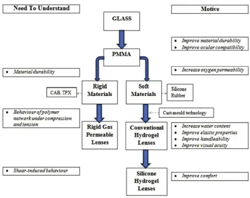
The first conception of a CL, as we know it today, appears with Leonardo da Vinci (1452-1519) in the sixteenth century, by a draft whose idea represents a concave glass structure supported over the eye.29 After several contributions, including John Hershel, Eugene Kalt and August Muller, appeared the first CL fabricated from ground glass. Although lens designs progressed over the following years from glass to polymers, none reached widespread use until the early 1970s. In 1936, polymethylmethacrylate (PMMA), a resin having greater clarity than glass, was introduced and promoted the development of first commercial CLs. Soft contact lens (SCL) became available to market in 1971 with the approval received by FDA for Bausch and Lomb, based on the discoveries of Witcherle and introduction of Polyhydroxyethylmethacrylate (P-HEMA).30,31 In later 1990, the first silicone hydrogel (SiHy) lens was marketed and set a stage for a new generation of SCLs. The first generation of SiHy presents a good permeability of oxygen, but slight stiffer and decreased wettability. The next generation appears with improvements in flexibility and wettability. The last and third
generation has better water content (WC) and decreased stiffness.32,33
Figure 4.1 summarizes the evolution of CL materials, relating the links between
materials and clinical success.34In 1994, 35 materials were available in USA and 90 materials
in the year of 2010.35
Many events and trends have been seen in last years that can have an important
impact in the CL industry today and in the future.36 According to industry estimates, there are
around 140 millions of wearers in the world. Annual data created by Morgan et al.37, present
the global spectrum of the evolution of the CLs market. Thus, the success of multifocal lenses has brought a greater number of older wearers and at the same time, some evidence also points to younger wearers, with a greater tendency to buy their lenses online.
Two-thirds of the lens fits are to females and the same rate represents “new fits”. Concerning lens materials, the proportion of gas permeable (GP) lenses fits has changed from 20% of fits in the late 1990s to about 10% to 15% over the past decade (figure
4.2). Overall, GP lenses accounted for 11% of all fits and orthokeratology (1%) appears with a
small increase compared to 2016, with greater representativeness (4% or more) in France, Hungary and the Netherlands. Soft lenses continue to dominate lens prescribing accounting 89% of new fits and 87% of refits worldwide. With the notable exception of Taiwan (18%), all markets prescribe at least 41% of soft lenses, with emphasis on Bulgaria with more than 90% of fits. The most marked change has been relative to the SiHy lenses, at which represent
three-quarters of all reusable soft lenses.Another important change has been the increase in
daily disposable lens prescribing, which represent one in four lenses fit today. The SiHy materials for this modality have lagged that of reusable lenses, probably due to its later launch, but 2017 marks the first year in which it is reported more SiHy than traditional
hydrogels for daily disposable prescribing.37
Figure 4.1. Schematic representation of key aspects of contact lens material development
According to U.S. Food and Drug Administration (FDA), hydrogel materials were classified into four groups based on water content (WC) and ionicity of the material (table
4.1). A subgroup for SiHy is being considered35 and more grouping systems with a surface criterion is being proposed considering the lens-solution incompatibilities. Green et al.33 show that preservative uptake in SiHy can be grouped by WC and ionic charge but there are evidences that hydrophobicity of SiHy lenses and the methods used to overcome it may also
influence interactions with components of LCS.38
The suffix “filcon” was adapted for hydrogel materials and the names of the CLs materials are regulated by United States Adopted Names Council (USAN) criteria. The FDA plays an important role in the development of American National Standards Institute (ANSI) standards. This entity is supported by associations such as the Contact Lens Institute, CL Manufacturers Association, American Optometric Association, American Academy of Optometry, American Academy of Ophthalmology and others. The International Organization for Standardization (ISO) includes approximately 20 countries associated and together with the ANSI development industry standards. Several ISO guidance documents are under current review with significant revisions.35
Figure 4.2. Major global trends in contact lens prescribing from 1997 to 2017 (Reproduced
Group 1 Low WC Non-ionic Group 2 High WC Non-ionic Group 3 Low WC Ionic Group 4 High WC Ionic Senofilcon A Lotrafilcon A Comfilcon A Omafilcon A Hilafilcon B Nelfilcon A Balafilcon A Etafilcon A Bufilcon A Etafilcon A Methalfilcon A Ocufilcon B
The materials in bold were included in this study.
CLs can be worn daily (DW), in which they are cleaned and removed every day and are replaced after a certain time (1 day to 1 year, but the most frequent is monthly replacement). The extended wear intends to use lenses for 7 days and 6 nights, being discarded at the end
of this time and continuous wear remain on the ocular surface for 30 days and 30 nights.40
Extended or continuous CL wear continues to be a delicate topic, which deserves additional
discussion.39 Overnight wear of CLs increases the risk of complications, especially microbial
infection. Although new FDA guidelines allow the continuous wear of one month, some researches have shown that this modality maintains the risk for subsequent corneal infection.41 In 2017, monthly substitution was the most used with 37% of fits, followed by daily disposable with 37%.37
The future of CLs walks around myopia control, personalization combined between aberrometers values and prescription, fluid dynamics used in multifocal design to autofocus capability, health monitoring systems (e.g: plan diet, blood sugar level, IOP), visual projection
as screens by LCD crystals and improvements like antibacterial coatings.32
4.2
Contact lenses – manufacturing techniques and designs
4.2.1
Manufacturing techniques
In the biomaterial’s world of CLs, improvements in the manufacturing processes and alternative designs make these an atrractive and effective option for non-invasive vision
correction.42 The typology, chemical structure and manufacturing techniques of the polymer
define its behavior, whether in concentrated or diluted solutions.
Table 4.1. Some examples of hydrogel materials (Adapted from Weissman BA et al, 2006).39
Table 4.2. Some exemples of hydrogel materials (Reproduced from Weissman BA et al, 2006).
Table 4.3. Some exemples of hydrogel materials (Reproduced from Weissman BA et al, 2006).
Table 4.4. Some exemples of hydrogel materials (Reproduced from Weissman BA et al, 2006).
CLs polymers are a complex and stable structure of macromolecules from the polymerization process that result from the combination of monomers in the presence of crosslinkers and initiators. The polymers can be classified considering the structure, chemical composition and shape. About the chemical composition, it can be used only one type of monomer (homopolymer) as PMMA or can be made more complex (copolymers).
The monomers are usually made of some combination of Carbon (C), hydrogen (H), oxygen (O), nitrogen (N), silicon (Si) and fluorine (F). The most adopted monomers in CLs production are methylmethacrylate (MMA), hydroxyethylmethacrylate (HEMA), methacrylic acid (MA), glyceryl methacrylate (GMA), Ethylene glycol dimethacrylate (EGDMA), N-vinyl pyrrolidone (NVP), methacryloxypropyl tris trimethylsiloxy silane (TRIS), polydimethylsiloxane (silicone) and fluoromethacrylates.
Materials of CLs not only depend of co-monomer compositions but are also influenced by the manufacturing method. The polymerization phase depends on the manufacturing
procedure and the most used techniques are lathe cutting, spin casting and cast molding.43,44
Lathed lenses are obtained from solid buttons of dry material, which are usually bulk polymerized over relatively long time. These buttons are further processed in computerized lathes submitted to low temperatures and low activation energies which may be responsible for the longer chains and, therefore, more chain entanglement.
On the other hand, spin casting is very quick, taking less than an hour to polymerase the final lens. The conditions are usually anaerobic (nitrogen purged) in order to minimize degradation effects. The monomer is placed on a rotating mold that will define the shape of the lens. Different CLs are obtained changing mold´s shape and speed of rotation. Similar, in cast molding, the polymerization also occurs by injecting a small amount of monomer in molds that will define the shape of the finished lens surface. Because it is a fast process and results in high quality lenses, this is the main method used today, particularly for disposable CLs.
The surface treatments enable better biocompatibility with the ocular surface.35,43 A
recent paper has demonstrated how a nanoemulsion polymerization technique can be used to create a transparent nanostructured polymer suitable for use as a UV-blocking photochromic SCL. The material was created by one-pot bicontinuous nanoemulsion and has
4.2.2
Specific designs
The lens design is the key in fitting any CL. The total diameter and base curve radius (BC) of the lens play relevant roles in the relation between the ocular surface and the CL (sagittal height). For instance, keeping diameter and decreasing BC the lens will be tightened
and closed on the ocular surface.46
Last year, around 45% of CLs users have 0,75 D or more of astigmatism in one or both eyes, so it was expected the same level of toric SCLs fits.37 This type of design requires stability for consistent visual performance which is obtained by means of stabilized rotation as for
example from prism-ballast, peri-ballast and thin-zone designs.47
Several studies about myopia progression control present alternatives with different lens designs. There are evidences that spherical SCL design can influence the peripheral defocus profile by myopic eye and several animal studies have demonstrated changes in the
shape of posterior chamber by defocus inducement.48 A recent review by González-Méijome
et al.49 reports a consistent and safe use of CLs in the regulation of myopia in children´s. Orthokeratology is the therapy with more effective outcomes in myopia regulation across different ethnic groups. The designs used are tetracurve and pentacurve reverse geometry for overnight corneal reshaping. At the same time, concentric ring bifocal and peripheral add multifocal SCLs are clinically effective for controlling myopia in school-aged children.50 Peripheral gradient lenses are another option that compensate central myopic errors and impose peripheral positive defocus.
Regarding presbyopia topic, monovision appears as the first modality and the preferred one for most of the 50-plis years it has been in use. Monovision consists of correcting the dominant eye for distance and the nondominant for near. However, in recent years new improvements in multifocal designs has changed this trend. Designs in common use on the market today are either center-distance or center-near. Today, the available designs
are segmented, such as crescent, executive and straight-top and concentric or annular.51
On the other hand, there are scleral CLs that are used for corneal irregulatities like keratoconus. These lenses have three zones, scleral (haptic) portion; vault, which is responsable for corneal and limbal clearance of the lens and optical section.52 The scleral
4.3 Contact lenses materials – main properties
Newer lens materials were developed to overcome problems of discomfort and hypoxia. The incorporation of crosslinkers, stabilizers, differing levels of WC and pigments increased lens softness and oxygen permeability.35,42 In this way, new available materials,
designs and modalities make the CLs wear safer and less prone to complications.32
CLs materials, which are placed in contact with a biological system (cornea, eyelids and tear film) and causes the minimum perturbation, can be tolerated by the host biological
system being considered biocompatible.54 The way a lens interacts with the tear fluid and the
top surface of cornea is the most important factor of lens material. When it satisfies all required bulk characteristics, it can be safely used. Biocompatibility can be better attained by surface treatment to minimize interactions, together with the desired bulk properties, such as high oxygen permeability, mechanical strength, softness, and optical properties. Overall, the CLs industry has achieved significant advances in improving the biocompatibility of SiHy lenses. 30,54
4.3.1 Optical properties – Refractive Index (RI)
In the group of SCLs, refraction index (𝑅𝐼) is an important physical parameter because of
its relationship with EWC, that have optical and physiological implications on lens behavior. 40,43
In general terms, 𝑅𝐼 (𝑛) is obtained through the ratio of the propagation speeds between different conditions (equation 1), where 𝑐 represents the velocity of light in vacuum corresponding
to the rate of propagation of the photons (𝑐 = 3 × 10⁸ m/s) and 𝑣 concerns to the transmitted
speed in the material. In addition to the density of the material, the RI also depends on the wavelength of incident light. In most of optical situations, when the light crosses in a dense space,
its speed will decrease according to its composition (𝑣 < 𝑐). An important exception is the X-ray,
where 𝑣 > 𝑐 and 𝑛 < 1. The higher frequency (shorter wavelength) of the incident light wave
translates a higher index.55
𝑛 = 𝑐
Specifically in CL, 𝑅𝐼 is determinated with a refractometer (Abbe, manual or automatic) 56
that allows objective measures at a low cost.57 Automatic refractometers can provide higher levels
of accuracy.58 Values of 𝑅𝐼 are around 1.38 to 1.41 for high WC and hydrogel CLs, and 1.42 to 1.44
for low and medium EWC and SyHi CLs. The WC of lenses and as well the dehydration after wear
can be estimated by 𝑅𝐼 of the polymer.56,59 So, for conventional hydrophilic lenses, higher
hydrated materials have a lower RI and materials with lower water content, have a higher 𝑅𝐼.57
There are evidences that after wear, SiHy CLs have greater capacity to retain or to reach their
initial EWC than conventional hydrogel CLs.60 About lens discontinuations, the dehydration is one
of the most important parameters. In vivo61 and in vitro62 studies have demonstrated that this
parameter may have ocular repercussions and depends on environmental conditions (relative humidity, air flow, temperature, illumination and atmospheric pressure) as on the lens type (chemical composition and design).
4.3.2
Optical properties – Transmittance (T), Reflectance (R) and
Absorbance (A)
As it happens with others optical elements, the transparency is an indispensable property in a CL.
As discussed in the previous section, the cross-process with a dense and flat interface, can cause a decrease of the velocity of a flat wave. In addition, this process is the source of reflection and refraction phenomena, which can be generically explained by the respective law of reflection and Snell´s law respectively.55,63,64 Roughly speaking, in the CL situation, where 𝑅𝐼 is larger compared with 𝑅𝐼 of air (𝑛 air ≈ 1), so 𝑛 i< 𝑛 t (a) and the light rays approach to the normal (N) (figure 4.3).
On other hand, if multiple reflections were neglected, when the angle of incidence is zero (b), the reflected and transmitted lights follow the normal axis and the fractions are given by: 64 𝑅λ= 𝐼 r 𝐼o= (𝑛t−𝑛i)2 (𝑛t+𝑛i)2 or %𝑅λ= 𝐼r 𝐼o × 100 Equation 2
The 𝑅λ represents the reflectance resulting from the reflected light and 𝑇λ the transmittance, whose result is given by refracted light. In an ideal situation, when scattering
light can be neglected, the light absorbed or absorbance (𝐴λ) by the CL can be obtained from
these fractions, through the following equation:64,65
𝑅λ+ 𝑇λ+ 𝐴λ= 1 or %𝑅λ+ %𝑇λ+ %𝐴λ= 100 Equation 4
All the processes reported (reflection, absorption, scattering and transmission) can lead to color production.65
Transmittance of UV-visible radiation in contact lenses – a hot topic
According to the ANSI Z80.20 standard, there are two classifications of UV-blocking CL
approved by FDA:67
• Class I: block 90% of UVA and 99% of UVB, recommended for high exposure environments such as mountains or beaches;
• Class II: block 70% of UVA and 95% of UVB, recommended for general environments. nt ni N Ɵi Ɵt Ɵr I0 It Ir (a) (b) I0 Ir It N
Figure 4.3. Schematic representation of the reflection and transmission light in a contact lens. (a) when a light beam with an initial intensity (I0), interact an optically denser material (ni <
nt), the transmitted light approaches the normal (N). (b) when the angle of incidence (Ɵi) is
There is an agreement between the recent studies that evaluate the effectiveness of
the protective lenses of the UVA and UVB radiation,67,68 emphasizing the Acuvue CLs with good
blocking values,69,70,71 including during phototherapy treatment.72 Compared to CLs without
UV filters, the UV-blocking lenses dramatically attenuate the UV spectrum of radiation.73 On
the other hand, lenses that do not incorporate UV blocking monomers showed some
attenuation of the UV spectrum.73,74,75 This phenomenon was explained previously by Bruce
et al.76 by the inherent ability of the silicone to absorb some UV radiation.
Table 4.2 includes the results of studies about this subject conducted in the 21st
century. The UV-blocking CLs can be especially important for aphakic patients,77 patients that
take drugs with a photosensitive effect and patients who spend a lot of time in outdoors activities.73 After wear, the UV-blocking lenses kept its filtering characteristics.78
The protection factor of CLs (𝑃𝐹) appears in several studies and was defined by Chou et al. as the inverse of transmitted light (equation 5). 79
Regarding to the wear of blue blocking (BB) spectacle lenses to improve visual performance or sleep quality, the results are still inconclusive.80 In this sense of blue light protection, there are guidelines for the adaptation of BB filters in populations at risk, especially in intraocular lenses (IOLs) 81,82.
𝑃𝐹 = 1
𝑇λ Equation 5
The wearing of UV-blocking CLs provided eye protection against all angles of incident light.83,84 The peripheral light focusing (PLF) demonstrated clinical implications in the anterior segment of the eye, especially in the development of pterygia and cortical cataracts. Thus, the peak of light intensity at the nasal limbus is approximately 20 times higher than the intensity of incident light.17,85
Figure 4.4 displays the focus of PLF in the anterior segment of eye. From the left side
we can see the intense nasal light focus that is a relevant factor in pterygia pathogenesis and on the right side the PLF in the inferior nasal quadrant, having effects on the early onset cortical lens opacity.11,17,86
4.3.3
Bulk properties - water content (WC)
Hydration properties of SCLs can hold clinical significance (Morgan & Efron, 2003).87 According to the FDA, WC is considered in lens classification as being low for less than 50% of WC and high for more than 50% (table 4.1).
The dehydration of SCLs during wear is a determinant key of their performance in eye. This process of water loss begins immediately after a CL is placed on the eye and is often associated with complaints of dryness and other related symptoms. The equilibrium water content (EWC) in the SCLs materials represents the ability of the hydrogel to bind water in its equilibrium state and depends on the chemical composition and crosslinking density of the polymer.88 The thickness of the material also affects the degree of dehydration that consequently has an impact on the ocular surface, since it is associated with surface deposit build-up, dryness symptoms and dehydration of the corneal epithelium. Lens dehydration also has the potential to affect ionic and hydraulic permeability, as reduce the lens movement and increasing the chance for microbial colonization. Other changes related with lenses dehydration are less flexibility, decrease of oxygen permeability and the base curve radius become steeper. 89,90 Paradoxically, in SCLs WC is a limiting factor in oxygen permeability, presenting an inverse relationship with Dk. On the contrary, the siloxane molecules in the matrix of SiHy have an extremely high permeability to oxygen, so lowering the WC of a SiHy material allows the silicone to become the main agent responsible for oxygen permeability, Figure 4.4. Optical representation of peripheral light focusing. a) intense nasal light focus (pterygia implications); b) transcameral and translenticular passage of PLF (implications in
early onset cortical lens opacity) (Adapted from Coroneo M., 2011).11
opacity
Table 4.2. Summary of results of studies about UV-blocking CLs in the 21st century.
Author/Year Instrumentation Contact Lenses UVA (%) UVB (%)
Harris et al. (2000)74 Shimadzu UV 160U Dual Beam Spectrophotometer Surevue Acuvue (2 week) Vistavue 1.5 - 89 3.2 - 91.3 83.2 - 88.4 1.3 - 3.7 2.9 - 9.0 60.2 - 83.2 Ali et al. (2005)69 Shimadzu UV160A Dual Beam Spectrophotometer Precision UV Igel Omega Encore UV Lunelle UV Surevue 2 Acuvue 2 8.92 46.51 46.61 53.91 9.01 11.51 3.0 4.72 4.22 7.55 3.92 2.83 Moore et al. (2006)75 Perkin-Elmer Lambda Dual beam Spectrophotometer Acuvue Advance Acuvue Oasys
Night & Day O2 Optix Purevision 21.07 18.35 85.16 80.71 69.90 0.16 0.03 68.64 62.89 35.97 DePry et al. (2013)72 Cary500 UV-vis Dual Beam Spectrophotometer Acuvue Oasys Acuvue 2 Proclear - - - 0.05 - 6.90 0.80 - 13.09 85.74 - 90.35 Rahmani et al. (2014)70 Special Cecil Spectrophotometer Acuvue Moist Zeiss Contact Day 30
Pretty Eyes AC Sauflon 56 UV 33 43 32 48 1.22 10.69 0.65 5.78 Rahmani et al. (2015)71 Special Cecil Spectrophotometer Acuvue Oasys Acuvue 2 Zeiss Contact Day 30
20.81 33.49 44.03 0.24 1.66 10.37