Multi-Platform Controller Interface for
SCADA Application ?
Jos´e Duarte∗ Lu´ıs Rato∗ Paulo Shirley∗∗ Manuel Rijo∗∗∗
∗Departamento de Inform´atica - Universidade de ´Evora, Rua Rom˜ao
Ramalho 59, 7000-671 ´Evora, Portugal ([email protected], [email protected])
∗∗DCeT - Universidade Aberta, Rua Fern˜ao Lopes, 9, 1o Esq.
1000-132 Lisboa, Portugal ([email protected])
∗∗∗NuHCC - N´ucleo de Hidr´aulica e Controlo de Canais
-Universidade de ´Evora - P´olo da Mitra Apartado 94, 7002-554 ´Evora Portugal ([email protected])
Abstract: This paper concerns the development of a SCADA-Controller Interface (SCI) application for an open-channel experimental facility. Water delivery canals are complex and spatially distributed systems. The proposed application is to be applied to test control algorithms developed by several research groups with different technical approaches. The proposed interface allows the development of controllers in different environments - C/C++, MATLAB/Simulink, and GNU Prolog - and may be easily extended to other environments. The experimental facilities with the used instrumented canal, the programmable logic controller (PLC) network and the SCADA system are also described in this paper. Finally, some software experimental results are presented.
Keywords: Multi-platform, Data acquisition, Control algorithms, Efficiency enhancement, Real-time communication, Supervisory control
1. INTRODUCTION
Management of water delivery systems is increasingly important as fresh water scarcity is becoming more and more a critical issue in many places worldwide. Thus an efficient management of water delivery canals, that minimizes water losses and/or energy consumption is a main issue.
Nevertheless, this management task brings about conflict-ing goals - water losses vs. service quality. On one side, users demand more and more flexibility on water delivery. On the other side, the use of the traditional water supply-oriented delivery schedules, like rotation (Almeida et al. (2002)) may attain a very low level of water losses but high price in terms quality of service of water delivery. Modern water delivery canals with sensors, automatic actuators, communication networks and the application of advanced control techniques may have an important role on the improvement of the water savings and water delivery service.
Several approaches have followed in order to address these questions, such as: distant vs. local control strategies, adaptive control, predictive control, and optimal control (Rijo (1999); Litrico and Fromion (2003); Shirley et al. (2007); Aguilar et al. (2009); Lemos et al. (2009)). A knowledge based system implemented in a declarative
? This work has been supported under project AQUANET - Decen-tralized and Reconfigurable Control for Water delivery Multipurpose Canal Systems (PTDC/EEA-CRO/102102/2008).
language as Prolog is another possible approach (Rato et al. (2005)).
These control approaches have been tested in the instrumented large scale experimental canal of the NuHCC -Hydraulics and Canal Control Centre of the University of ´Evora, using several developed software packages that communicates to the Supervisory Control and Data Ac-quisition (SCADA) system. These approaches have been developed on different programming environments such as C/C++, Visual Basic, and Matlab and resulted in non compatible software packages
The interface presented in this paper aims to establish a common framework for control algorithm development at this experimental plant.
2. WATER CANAL DESCRIPTION
This project is being developed at the NuHCC (Fig. 1). NuHCC activity began in 2001 and was financed by the European Union (Program INTERGET IIC).
The canal used has a trapezoidal lined cross section geometry and is constituted by four pools of roughly 40 m each, resulting in a 145 m long instrumented canal. The facility also includes a traditional water delivery canal that completes a closed water circuit. The canal inflow is manipulated by an electrical controlled MONOVAR valve. The water depth profiles along the four pools may be controlled by three sluice gates and one overshot gate (vertical). Upstream of each gate there is an offtake that
Fig. 1. Experimental water canal at the University of ´
Evora
feeds directly the traditional local upstream controlled canal. Each offtake is equipped with a flowmeter and an electrical butterfly valve. Concerning sensors, there are three float and counter-weight water level sensors in stilling wells for each pool - one at each end and another one in the middle of the pool. Fig. 2 shows a schematic diagram of the experimental plant. This facility is described in more detail in Ratinho et al. (2002) and Almeida et al. (2002).
Fig. 2. Schematic diagram of the experimental water canal at the University of ´Evora
2.1 Data acquisition and Supervision System
The experimental facility is also equipped with a network of 6 PLCs. Five local PLCs (one for each gate and one for the intake valve) and one central master PLC. The data acquisition and analog-to-digital conversion are performed locally at each PLC. These are interconnected by a MOD-BUS network to the master PLC, that communicates to the SCADA computer by a serial port RS232 interface. See Fig. 3.
Fig. 3. Schematic diagram of the PLC network and SCADA PC server.
The SCADA system is built over the WIZCON environ-ment, that presents a user friendly graphical interface (Fig. 4) to command the process as well as to observe
the evolution of the measured variables over time. The environment runs only on Windows Operating System.
Fig. 4. Main screen of SCADA graphical interface at the SCADA PC server
3. SCADA-CONTROLLER INTERFACE (SCI) APPLICATION
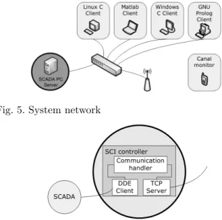
The developed SCI application implements a client-server architecture with one server in the SCADA computer and several clients. The clients and server may communicate by TCP/IP (Kozierok (2005)) connection over a computer network on separate hardware, but both may run in the same computer. The computers of this network may run different Operating Systems. In order to cope with this multiplatform environmemnt, several clients were created in C/C++, Prolog, and Matlab environments.
These (controller-side) clients communicate with the server by TCP/IP connection (Fig. 5), while the server communicates with the SCADA environment by Dynamic Data Exchange (DDE). This scheme is represented in Fig. 6.
Fig. 5. System network
Fig. 6. Controller Server architecture
The major benefit of this system architecture is to al-low multi-platform controller side tests. At the present
moment, the users of the experimental plant can de-velop their controllers among Windows and Linux, and choose the programming environmemnt: C (Kernighan and Ritchie (1988)), Prolog (Diaz (2009)) or Matlab (Chapman (2008)). Other programming environments such as Java, C#, and Python will be developed.
3.1 Server
The server that the SCI needs to run on the SCADA PC. Since this implies that it must run on a Windows machine, so the server module was developed on ANSI C for Windows.
The server module implements three components: TCP server, communication handler and DDE Client. The mod-ule architecture can been seen in Fig. 6.
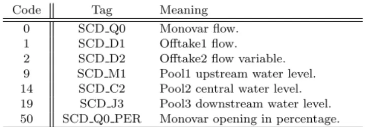
TCP Server This module waits for connections from the clients and then sends and receives TCP messages. The server is ready to answer to any requests from any SCI Client, even from different platforms. In order to ensure that, a communication protocol was created. This protocol defines the format and a set of rules for exchanging all messages. This set of rules includes a list of keywords (tags) to easy reference SCADA variables. A partial list of tags is presented in Table 1.
Table 1. Tags examples
Code Tag Meaning
0 SCD Q0 Monovar flow.
1 SCD D1 Offtake1 flow.
2 SCD D2 Offtake2 flow variable.
9 SCD M1 Pool1 upstream water level.
14 SCD C2 Pool2 central water level.
19 SCD J3 Pool3 downstream water level.
50 SCD Q0 PER Monovar opening in percentage.
The client can request a set of actions of the same type each time it sends a message to the server (e.g. the request to read four different variables can be done with one command). The message used on the client server TCP/IP connection has the following format:
number_of_actions,action1,action2,...,actionN# E xample: If the client wants to read the monovar, offtake 1, offtake 2 and offtake 4 flow variables, the message should be (before encoding):
[SCD_Q0, SCD_D1, SCD_D2, SCD_D4] After encoding the message will be: 4,0,1,2,4#
DDE Client The SCADA system has a DDE communi-cation interface. It was the chosen process of interaction between the SCI Server and the SCADA system.
The SCADA interacts with the master PLC (via a serial link) setting and reading variables are communicated to the slave PLCs via the ModBus network. These variables are identified by tags and represent a state of the controlled plant, includes: sensor measures, setpoints and gains for the local controllers and operation modes.
The Controller Server implements a DDE Client that connects to the SCADA DDE Server and allows to read and write those variables through DDE. To ensure that, three functions were defined:
• DDEInit(”WIZCON”, ”GATE”) to establish client-server DDE connection.
• DDERequest(char var[]) to read values.
• DDEPoke(char []var, char []valor) to write values. However, while reading usually needs just one call to DDERequest(), to define a command into the actuators several calls of DDEPoke(...) are usually necessary, stating the control mode of one or more (cascade) loops and defining the variable value.
For example, the code to command gate 1 opening set-point (tag ”SCD U1 SP”, code ”105”) is
case 105: /* gate 1 opening set-point */ DDEPoke("SET_MATIC_OPEN_A2",arg2); DDEPoke("MODE_MATIC_A2", "2");
Communication handler This module works like a lan-guage interpreter of the SCI Server. It must handle the requests and responses between TCP server and the DDE client.
3.2 Clients
The main objective of the client system is to allow the interaction with SCADA using any Operating Systems or programming languages. Several interface clients (ICs) have already been developed and much more can be implemented. At this moment, four ICs are available and fully tested: ANSI C for Windows, ANSI C for Linux, GNU Prolog and Matlab. Each ICs implements a couple of functions to interact with SCADA: scd read and scd write. • scd read - Send a request to the SCI server to read a
list of SCADA variables.
• scd write - Send a request to the SCI server to write/change a list of variables.
The user can use, in his code or simulation (Mat-lab/Simulink), any of these functions to read or write values of SCADA variables.
A stub to read four SCADA variables in ANSI C (Windows or Linux) is #include "scd_client.c" (...) int in[4] = {SCD_J1, SCD_J2, SCD_D1, SCD_D2}; double out[4]; scd_read(in, 4, out);
First of all, a list of tags to read should be created and then make the read request. In this case, the variable out will keep the four requested values.
Similarly, in gprolog the equivalent stub would be
:-include(scd_client). (...)
read_test(Output_values):-scd_init( StreamIn, StreamOut ), scd_read( StreamIn, StreamOut,
[’SCD_Q0’,’SCD_D2’,’SCD_D3’,’SCD_J4’], Output_values),
scd_end(StreamIn,StreamOut).
The predicate read test(?Output values) starts by initial-izing the connection with the SCI server, doing the read request and finally end the connection. The variable Out-put values will hold a list with the four values requested. In Matlab, a single function call can be used to read the same four variables,
ouput = scd_read([’SCD_Q0’;’SCD_D2’;’SCD_D3’;’SCD_J4’]);
where the variable output holds the four requested values. 3.3 Canal monitor for cellphones
A canal monitor (Fig. 7) has been developed for Symbian 60 cellphones using the SCI. Using an wireless connection and a cellphone, it is possible to read several SCADA variables. This feature is very usefull on long controlling tests, because it allows the researcher to check anyware if everything is working as expected.
Fig. 7. Canal monitor for cellphones
4. LATENCY TESTS
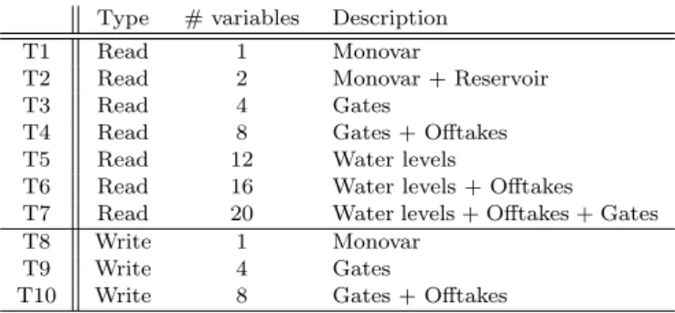
Several tests were made in order to evaluate the latency of the read and write operations i.e. time delay between the operation request and result retrieval. Table 2, presents the test results. These tests were defined based on the most frequently used commands. For each test, 600 samples were taken with a period of 1 second. All tests were performed on a Intel(R) Core(TM)2 Duo CPU P8700 (2.53Ghz), 4GB of RAM, with an Ethernet connection 10/100 Mbits.
Table 2. List of the lantency tests
Type # variables Description
T1 Read 1 Monovar
T2 Read 2 Monovar + Reservoir
T3 Read 4 Gates
T4 Read 8 Gates + Offtakes
T5 Read 12 Water levels
T6 Read 16 Water levels + Offtakes
T7 Read 20 Water levels + Offtakes + Gates
T8 Write 1 Monovar
T9 Write 4 Gates
T10 Write 8 Gates + Offtakes
It was decided to run these tests in MATLAB and C because these are the main tools used by the researchers of the ongoing project. Tables 3 and 4 shows all reading test in C and Matlab respectively.
Table 3. Readings tests using C for Windows.
(Values in milliseconds) T1 T2 T3 T4 T5 T6 T7 Mean 3.1 3.2 3.4 4.0 4.1 4.4 4.8 Median 3.0 3.0 3.0 4.0 4.0 4.0 5.0 Mode 3 3 3 4 4 4 5 Std. Deviation 0.5 0.6 0.6 0.9 0.7 1.3 1.0 Maximun 12 12 11 22 18 31 24 Minimun 2 2 2 2 2 3 3 Range 10 10 9 20 16 28 21 Percentile 25 3 3 3 4 4 4 5 Percentile 50 3 3 3 4 4 4 5 Percentile 75 3 3 4 4 4 5 5
Table 4. Readings tests using MATLAB.
(Values in milliseconds) T1 T2 T3 T4 T5 T6 T7 Mean 14.9 23.0 34.7 45.5 55.3 65.8 76.1 Median 15.0 23.0 37.0 45.0 55.0 65.0 73.5 Mode 15 23 38 42 55 63 70 Std. Devia-tion 2.3 2.1 4.9 7.2 6.7 8.4 9.5 Maximun 47 37 46 71 85 109 124 Minimun 6 9 14 21 31 39 56 Range 41 28 32 50 54 70 68 Percentile 25 15 23 31 41 51 61 70 Percentile 50 15 23 37 45 55 65 74 Percentile 75 15 23 38 49 59 69 81
In Tables 5 and 6, are shown all writing tests in C and Matlab respectively.
Table 5. Writing tests using C for Windows.
(Values in milliseconds) T8 T9 T10 Mean 50.8 215.9 432.3 Median 50.0 211.0 429.0 Mode 39 207 445 Std. Deviation 15.9 22.0 19.1 Maximun 87 278 473 Minimun 30 176 402 Range 57 102 71 Percentile 25 39 199 418 Percentile 50 50 211 429 Percentile 75 63 231 445
Table 6. Writing tests using MATLAB.
(Values in milliseconds) T8 T9 T10 Mean 58.1 254.5 484.6 Median 57.0 254.0 483.0 Mode 58 235 479 Std. Deviation 11.2 20.2 29.6 Maximun 100 310 560 Minimun 37 200 400 Range 63 110 160 Percentile 25 49 239 462 Percentile 50 57 254 483 Percentile 75 65 266 508
In the results shown results, the maximum latency is 560 ms, when writing 8 variables (T10 - Matlab), which is compatible with sampling periods of 5 s. This is the usual sampling time value for prototypes and physical models similar to the used canal. (Rato et al. (2007); Aguilar et al. (2009)).
5. DATA AQUISITION AND CONTROLLERS TESTS This section presents the ongoing research work of two teams using SCI presented in the paper.
5.1 Example 1 - Calibrating A Finite Dimension Model A white box nonlinear simulator for water delivery canals has been tested and validated for the experimental facility here presented using the IC for MATLAB. The Saint-Venant equations, used for describing the transport phe-nomenon, are linearized and then discretized leading to a time discrete state space representation for the canal pool dynamics (Nabais and Botto (2010, 2011)). This pool model has several interesting features namely:
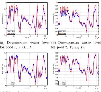
• as the pool model state space is constituted by water depths and discharge along the pool axis, it allows for water depth monitoring along the canal axis (Fig.8(c) and Fig.8(d));
• the pool model accept as boundary conditions dis-charge and water depth, so the pool model can be used for water conveyance networks as a connection between reservoirs;
• the pool model accounts for discharge perturbations along the pool axis, this way is possible to use the model to develop algorithms for leak detection and localization in open water delivery canals;
• it’s simplicity, the Saint-Venant equations are solved through matrices multiplications, with a low compu-tational cost is of particular importance when dealing with large scale systems like the used canal.
In Fig. 8, are presented several water depths for different locations in the canal. The canal was divided in four pools and subjected to variations of the inflow, gate opennings and outflows. Under this severe scenarios, with a large deviation from the stationary configuration, the nonlinear canal simulator captures the systems dynamics and in particular the meaningful water depths have a Variance Accounted For over 88% to 97% and a Medium Absolute Error of 15mm.
The proposed representation is well suitable for model based control strategies namely Model Predictive Control. 5.2 Example 2 - LQG/LTR and D-SIORHC control In order to design controlers, obtained around the desired equilibrium point, with a sampling interval of 1 s. This data is then decimated to the desired controller sampling period, either 2 s or 5 s. After de-trending and filtering data, this is used to identify MIMO linear input/output models relating gate positions and pool water levels (at the desired sections). From these i/o models state-space realizations are then build. For decentralized control, the models have a structure that fits the design algorithm used.
Fig. 9 shows results obtained with the well known discrete time LQG/LTR algorithm for a single pool. Although mul-tivariable LQG/LTR has already been tried with success, these results are shown for the sake of illustration. In this algorithm, the controller acts to optimize the quadratic cost function
0 0.5 1 1.5 2 2.5 x 10⁴ 0.5 0.55 0.6 0.65 0.7 0.75 time [s] water depth [m] Canal Model
(a) Downstream water level
for pool 1, Y1(L1, t). 0 0.5 1 1.5 2 2.5 x 10⁴ 0.5 0.52 0.54 0.56 0.58 0.6 0.62 0.64 0.66 0.68 0.7 time [s] water depth [m] Canal Model
(b) Downstream water level
for pool 2, Y2(L2, t). 0 0.5 1 1.5 2 2.5 x 10⁴ 0.45 0.5 0.55 0.6 0.65 0.7 time [s] water depth [m] Canal Model
(c) Water depth in the middle
of pool 1, Y1(L1/2, t). 0 0.5 1 1.5 2 2.5 x 10⁴ 0.46 0.48 0.5 0.52 0.54 0.56 0.58 0.6 0.62 0.64 0.66 time [s] water depth [m] Canal Model
(d) Water depth in the middle
of pool 2, Y2(L2/2, t).
Fig. 8. White box model validation for a open water canal, subjected to upstream discharge, gate movement and water extraction variation.
Fig. 9. LQG/LTR algorithm J = ∞ X t=0 (|e(t)|2+ ρ|u(t)|2) (1)
where e is the tracking error, u is the manipulated variable and ρ is a positive weight. At the instant 300 s, the lateral offtake of the water delivery canal has been opened, causing the gate to close to keep the pool water level close to the setpoint. After that, the setpoint has been increased. The response shows the typical oscillatory behavior of LQG controllers. This can be avoided either by the in-crease on the weight ρ (at the cost of making the response sluggish!) or by changing the basic algorithm.
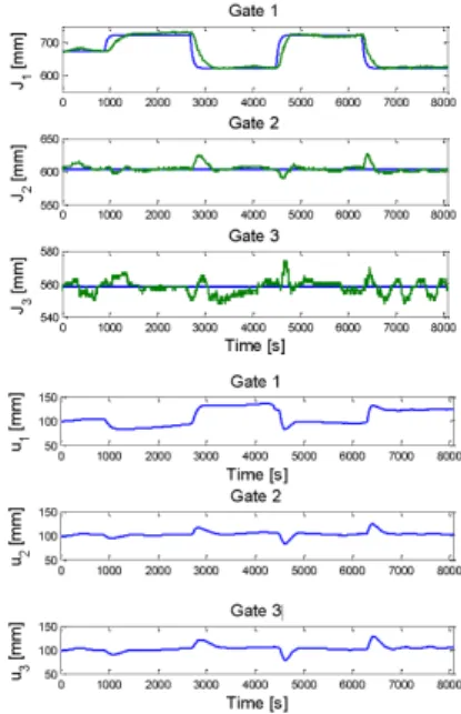
Fig. 10 shows results obtained with D-SIORHC, a dis-tributed version of the SIORHC predictive controller, ap-plied to three canal pools. This is a model predictive con-trol algorithm that minimizes a receding horizon cost un-der the constraint that the final state vanishes at the end of the prediction horizon. This so-called stability constraint ensures, under certain conditions, that the algorithm yields a stable closed loop for a finite prediction horizon. The distributed version assumes that local pool models interact with adjacent pools via the manipulated variables (gate positions). According to a procedure that resembles a Nash game local controllers negotiate the optimal gate positions such as to reach a consensus. As apparent from Fig. 10,
Fig. 10. D-SIORHC predictive controller
the stability constraint leads to a control law that avoids the oscillatory behavior of GPC.
It is remarked that these examples are presented just for the sake of illustration of the use of the IC for MATLAB and that no effort has been presented to optimize results. The point to stress is that this interface allows easy prototyping of controllers for the water delivery canal.
6. CONCLUSION AND PERSPECTIVES A SCADA-Controller Interface was developed and a framework was proposed in order to establish a common interface an automatic experimental water delivery canal. This approach will permit the development of very differ-ent control algorithms, implemdiffer-ented in several programing environments and running in two operating systems -Gnu/Linux and Windows. This framework is a key step to promote the reuse and comparison of advanced control algorithms in the NuHCC experimental canal.
In a near future, a SCI emulator will be developed. This emulator will implement a TCP Server and a communica-tion handler as well, but it will not implement the DDE Client. This emulator will respond to the ICs, that should not notice the difference between the real system and the emulator from the software point of view. The emulator should also simulate the dynamical behavior of the canal. The main goal of this emulator is to simulate the SCADA application behavior, so that it will provide a first level of debugging for any new controller applications. Thus, when a new control algorithm is proposed, it will be tested in the experimental plant, after successfully passing the emulator test.
ACKNOWLEDGEMENTS
The results shown in Fig. 9 and 10 concern to research work which has been performed by J. M. Lemos, L. F. Pinto, F. M. Cadete and J. M. Igreja from INESC-ID. The results shown in Fig. 8 concern to research work which has been performed by J. Nabais and M.A. Botto
through IDMEC by the Associated Laboratory in Energy, Transports, Aeronautics and Space.
REFERENCES
Aguilar, J., Langarita, P., Linares, L., and Rodellar, J. (2009). Automatic control of flows and levels in an irri-gation canal. Industry Applications, IEEE Transactions on, 45(6), 2198–2208. doi:10.1109/TIA.2009.2031941. Almeida, M., Figueiredo, J., and Rijo, M. (2002). Scada
configuration and control modes implementation on an experimental water supply canal. In 10th Mediterranean Conference on Control and Automation, Lisbon, Portu-gal.
Chapman, S.J. (2008). MATLAB Programming for Engi-neers. Cengage Learning, 4 edition.
Diaz, D. (2009). GNU PROLOG - A Native Prolog Compiler with Constraint Solving over Finite Domains. 1.9 edition.
Kernighan, B.W. and Ritchie, D.M. (1988). C Program-ming Language. Prentice Hall, 2 edition.
Kozierok, C.M. (2005). The TCP/IP Guide: A Compre-hensive, Illustrated Internet Protocols Reference. No Starch Press, 1 edition.
Lemos, J.M., Machado, F., Nogueira, N., Rato, L., and Rijo, M. (2009). Adaptive and non-adaptive model predictive control of an irrigation channel, networks and heterogeneous media,. AIMS- American Institute of Mathematical Sciences, Special Issue on Irrigation Channels and Related Problems, Volume: 4, Number: 2, 303 – 324.
Litrico, X. and Fromion, V. (2003). Advanced control politcs and optimal performance for an irrigation canal. In Proceedings of the 2003 European control conference, Cambridge, UK.
Nabais, J. and Botto, M.A. (2010). Qualitative comparison between two open water canal models. In 9th Portuguese Conference on Automatic Control, Coimbra, Portugal. Nabais, J. and Botto, M.A. (2011). Linear model for
open water canal pools. In 8th Internation Conference on Informatics in Control, Automation and Robotics, Noordwijkerhout, Netherlands (Submitted).
Ratinho, T., Figueiredo, J., and Rijo, M. (2002). Mod-elling, control and field tests on an experimental irriga-tion canal. In MED’2002, 10th Mediterranean Confer-ence on Control and Automation, Lisbon, Portugal. Rato, L., Rodrigues, I.P., and Gomes, R. (2005).
Knowl-edge representation approach to closed loop control sys-tem - a tank syssys-tem case-study. In J. Filipe, J. Andrade-Cetto, and J.L. Ferrier (eds.), ICINCO, 113–118. IN-STICC Press.
Rato, L., Salgueiro, P., Lemos, J.M., and Rijo, M. (2007). Adaptive predictive controller applied to an open water canal. In J. Zaytoon, J.L. Ferrier, J. Andrade-Cetto, and J. Filipe (eds.), ICINCO-SPSMC, 357–360. INSTICC Press.
Rijo, M. (1999). Local automatic control modes in an ex-perimental irrigation canal. In Irrigation and Drainage System, volume 17, 179–193. Kluwer Academic Pub. Shirley, P., Lemos, J., Nogueira, N., and Machado, F.
(2007). Model analysis and control of a four segment irrigation canal. 1–6. doi:10.1109/MED.2007.4433678.