UNIVERSIDADE DE LISBOA
FACULDADE DE CIÊNCIAS
DEPARTAMENTO DE QUÍMICA E BIOQUÍMICA
Polymorphism in Hydroxybenzoyl Compounds:
Structure and Energetics
Cátia Sofia Duarte Lopes
Mestrado em Química
Especialização em Química
Dissertação orientada por:
Doutor Carlos Eduardo Sabino Bernardes
Professor Manuel Eduardo Ribeiro Minas da Piedade
iii
To my little sister
and
v
Acknowledgments
First and foremost, I would like to thank Professor Dr. Manuel Eduardo Minas da Piedade, for accepting me in his group and giving me the opportunity to work with him. During this year, it was due to his knowledge and guidance that I was able to develop new essential skills to make good science. Thank you for all the valuable advice that helped me grow scientifically and personally. Also, for all the chocolates that always gave me an extra push when the work was not going so well. Dr. Carlos Eduardo Sabino Bernardes, who was always available to answer my questions and to help me whenever an obstacle appeared in the development of this work. A special thanks to both of them for all the patience, understanding and good disposition during the development of this work.
Although far away, a very special thanks to Dr. Ricardo Alexandre Gravata Simões for all his support since the very beginning of my adventure in the Molecular Energetics Group and always telling me to keep calm. Also to Dr. Abhinav Joseph for helping me understand some of my results, being available for the discussion of those with me and for saving me whenever a technical problem in the apparatus came up. Also, to all my laboratory colleagues, Rafael Bento, Miguel Rendas, and in particularly Mariana Donato, thank you for all the laughs and funny moments that passed this year. Those always helped me maintain a good mood while working.
The development of this work had several contributions from many people that without their help it would have been hardly obtained. First, I would like to say thanks to Professor Dr. Maria da Conceição from IST-UL for the HPLC analysis. Professor Dr. Hermínio Diogo from IST-UL for the differential scanning calorimetry measurements and hot stage microscopy images which assisted in identifying important results in this work. Professor Dr. Fátima Piedade from DQB-UL for the single crystal structures which without those this work would not have been completed and finally Dr. Filipe Agapito for the computational calculations which were essential to do the energetics part of this work.
Sara Realista, thank you for always inspiring me to work hard, do better and never give up, without you this journey would not have been the same and I do not know where I would be. You always made me laugh even when depressed. Paulo Martinho and Marta Saraiva, thank you both for all your wise advice and support which always helped me see things from another perspective. Also, Priscilla Ramgi, who always accompanied me in this hard journey. Thank you for all the cheering “pius”. The four of you will always be in my heart and will never be forgotten! Ana Catarina Rosális, my longest friend, who has seen the ups and downs of this rollercoaster that has been this journey. Thank you for always holding my hand and keeping my head straight when my judgment got clouded.
My family, Rui Lopes, Ana Paula Lopes, Ricardo Lopes and Mafalda Lopes, for all the support they gave me to get to the top of this ladder. In particular, my mother, who is always giving me strength to go on and to never give up no matter what comes in my way. My sister, a million thanks for all the help done throughout these years, reviewing all of my works and searching for errors which always led to the most hilarious corrections and helping me with image edition. To all the Serrão family, for their amazing support throughout these years, specially Helena and Nelson Serrão, who are like second parents to me.
Last but not least, a huge thanks to Ricardo Serrão, for all your patience, all your trust, for always believing in me, never panicking and always seeing the bright side even when I did not. You are the most important person in my life and who made one of my greatest dreams possible through our combined hard work.
vii
Resumo
O trabalho apresentado nesta tese foi realizado no Grupo de Energética Molecular (GEM), do Centro de Química e Bioquímica da Faculdade de Ciências da Universidade de Lisboa. Um dos temas principais desenvolvidos ao longo dos anos no GEM, prende-se com o estudo da relação entre a energética e a estrutura das moléculas, nomeadamente em sólidos moleculares orgânicos. A abordagem deste tema tem seguido duas linhas de investigação ligeiramente distintas. Na primeira, são estudados sistemas modelo, normalmente constituídos por pequenas moléculas (poucas dezenas de átomos), pouco dispendiosos e que podem ser facilmente manipulados. Estes estudos têm como objetivo estabelecer relações causa-efeito como, por exemplo, averiguar como uma determinada alteração na estrutura de uma molécula, implica mudanças no empacotamento em estado sólido e, consequentemente, nas propriedades físicas. Na segunda linha, os conhecimentos retirados do estudo dos sistemas modelo, são aplicados diretamente ao estudo de compostos com interesse comercial. De facto, este tipo de estudo é de extrema importância para as indústrias que usam formulações orgânicas no estado sólido, onde a indústria farmacêutica se destaca, devido à grande variedade de princípios ativos farmacêuticos que são utilizados em estado sólido.
Quando se trabalha com sólidos moleculares cristalinos por vezes, uma mesma molécula pode organizar-se com diferentes arranjos tridimensionais. A este fenómeno dá-se o nome de polimorfismo. Dado que cada forma cristalina pode apresentar diferentes propriedades físicas (e.g. cor, temperatura de fusão e solubilidade), o controlo e previsão deste fenómeno é hoje em dia crucial para a indústria. Por exemplo, para a indústria farmacêutica, se duas formas cristalinas do mesmo composto apresentarem solubilidades distintas, podem conduzir a uma biodisponibilidade diferente do medicamento no organismo do paciente. Apesar de poderem existir vários polimorfos para uma molécula em determinadas condições de pressão e temperatura, apenas uma dessas formas é termodinamicamente estável. Assim, caso não existam barreiras cinéticas, todas as formas metastáveis tendem a evoluir para a fase mais estável. Neste sentido, torna-se importante conhecer a relação energética entre as fases, a fim de evitar problemas durante, e.g. processos de armazenamento. Estes tipos de problemas podem, por esse motivo, levar a uma eventual recolha dos medicamentos baseados num dado principio ativo, e assim levar a perdas monetárias muito elevadas para a indústria.
É de realçar, no entanto, que se o polimorfismo for bem compreendido e controlado, pode levar ao desenvolvimento de novos materiais, que possuem características físicas diferentes do material de partida, que podem ser ajustadas para uma determinada aplicação sem alterar a molécula inicial. Este facto, mostra que é de todo o interesse conhecer quais os vários polimorfos existentes para cada molécula, e estudar a maneira mais adequada para os preparar e controlar.
É neste âmbito que surge o trabalho que foi desenvolvido nesta tese. Este foi realizado como continuação dos estudos iniciados no GEM para os compostos 4’-hidroxiacetofenona e 4-hidroxibenzaldeído. Ambos podem ser considerados sistemas modelo que pertencem à família de compostos do tipo 4-hidroxibenzoílos (HOC6H4COR). Estes revelaram-se ser compostos com a
capacidade para gerar polimorfos, pois tanto para a 4’-hidroxiacetofenona (R = CH3) como para
o 4-hidroxibenzaldeído (R = H) já foram identificadas duas formas cristalinas diferentes. Para além destas, no caso da 4’-hidroxiacetofenona, foram também identificados três hidratos. A razão principal que leva a esta diversidade parece estar relacionada com a capacidade destas moléculas poderem formar diferentes tipos de ligações de hidrogénio como OH∙∙∙O, CH∙∙∙Ocarbonilo e
CH∙∙∙Ohidroxilo, permitindo diferentes empacotamentos cristalinos. Para além disso, do ponto de
vista conformacional, nesta família de compostos, as moléculas podem ainda adotar duas conformações distintas, que diferem na orientação do átomo de hidrogénio do grupo hidroxilo
viii relativamente ao grupo carbonilo. Assim, um dos objetivos principais deste trabalho foi verificar de que forma um aumento do tamanho da cadeia alquilo, i.e. a introdução de um grupo apolar R progressivamente maior, influencia a formação de diferentes estruturas cristalinas. Para isto foram selecionadas quatro moléculas, em adição à 4’-hidroxiacetofenona e 4-hidroxibenzaldeído, aumentando a cadeia carbonada consecutivamente, através da adição de grupos CH2. Neste
sentido, foi realizado um estudo sistemático da energética e das estruturas cristalinas da 4’-hidroxipropiofenona (R = C2H5), da 4’-hidroxibutirofenona (R = C3H7), da
4’-hidroxivalerofenona (R = C4H9) e da 4’-hidroxiheptanofenona (R = C6H13).
O ponto de partida para o desenvolvimento deste trabalho, foi a caracterização energética para os compostos selecionados, dada a ausência na literatura de dados fiáveis para estes compostos. Este estudo envolveu várias etapas: i) a determinação das temperaturas de fusão e respetivas entalpias de fusão molares padrão (po = 1 bar) , ∆
fusHmo, por calorimetria diferencial de varrimento; ii) a avaliação da entalpia de vaporização molar padrão, ∆vap𝐻mo, da hidroxivalerofenona e 4’-hidroxiheptanofenona, e de sublimação molar padrão, ∆sub𝐻mo, da hidroxipropiofenona e 4’-hidroxibutirofenona, por microcalorimetria Calvet; iii) a determinação das capacidades caloríficas molares padrão dos compostos por calorimetria diferencial de varrimento, de forma a possibilitar a correção dos valores de ∆vap𝐻mo e ∆sub𝐻mo obtidos nas condições experimentais, para entalpias de sublimação molares padrão à temperatura de referência de 298,15 K, ∆subHmo(298,15) iv) o cálculo das entalpias de formação molar padrão em estado sólido, ∆fHmo(cr), a partir dos valores de ∆subHmo(298,15) e das entalpias de formação molar padrão em fase gasosa, ∆fHmo (g), à temperatura de 298,15 K. Este trabalho foi recentemente publicado (C. S. D. Lopes, F. Agapito, C. E. S. Bernardes, M. E. Minas da Piedade Thermochemistry of 4-HOC6H4COR (R = H, CH3,
C2H5, n-C3H7, n-C4H9, n-C5H11, and n-C6H13) Compounds; J. Chem. Thermodyn. 2016, DOI:
10.1016/j.jct.2016.09.026). Foi realizada uma correlação linear entre as entalpias de sublimação molares padrão a 298,15 K dos compostos com o número de átomos de carbono (R2 = 0,986).
Este resultado sugere que apesar dos diferentes empacotamentos cristalinos existentes entre as várias formas a energia de coesão é aditiva, com um aumento por cada CH2 de 6,6±0,6 kJ∙mol-1.
A procura de novos polimorfos nos compostos estudados foi realizada, numa primeira etapa, pela verificação da existência de transições de fase e avaliando as temperaturas de fusão dos materiais, por calorimetria diferencial de varrimento. De uma forma geral, os ensaios realizados com os materiais de partida, não revelaram a existência de transições de fase entre a temperatura ambiente e de fusão. No caso da 4’-hidroxivalerofenona (HVP), após avaliar a fusão da amostra, esta foi ainda submetida a ciclos de aquecimento/arrefecimento. Este estudo revelou que o material que precipita a partir do líquido isotrópico da HVP, não apresenta transições de fase na gama de temperaturas estudada (153 K a 453 K). No entanto, a temperatura e entalpia de fusão são significativamente diferentes em relação à amostra inicial: enquanto o composto de partida (forma I), que é preparado por cristalização em etanol, apresenta uma temperatura de fusão de 334,20,7 K, e uma entalpia de fusão molar padrão de 25,75±0,26 kJ·mol-1, a que precipita a
partir do líquido isotrópico (forma II), funde a 324,0±0,2 K e tem uma entalpia de fusão molar padrão de 18,14±0,18 kJ∙mol-1. Utilizando os valores de entalpia e temperatura de fusão, foi
possível concluir que a forma I é termodinamicamente mais estável que a forma II, e que estas se encontram relacionadas monotropicamente. Os resultados destes estudos termoanalíticos sobre o polimorfismo na HVP foram já submetidos para publicação estando a aguardar o resultado da avaliação (C. S. D. Lopes, C. E. S. Bernardes, M. F. M. Piedade, H. P. Diogo, M. E. Minas da Piedade; A New Polymorph of 4′-Hydroxyvalerophenone Revealed by Thermoanalytical and X-ray Diffraction Studies; Eur. Phys. J.). A identificação deste novo polimorfo da HVP foi ainda verificada através de estudos de difração de raios-X de cristal único, os quais permitiram determinar a organização molecular desta nova fase em estado sólido. Para além destes resultados
ix para a 4’-hidroxiheptanofenona (HHP), recorrendo a dados de difração de raios-X de cristal único, foram resolvidas quatro estruturas a diferentes temperaturas (150 K, 190 K, 220 K e 293 K) e identificada uma transição de fase entre 190 K e 220 K. Verificou-se que todas estas estruturas são ortorrômbicas, sendo que a transição de fase que ocorre, leva à alteração do grupo espacial, de P212121 para Pnma, confirmando assim a existência de polimorfismo na molécula. Esta
transição também foi identificada por calorimetria diferencial de varrimento. Finalmente, a partir da análise dos dados de difração de raios-X de cristal único das diferentes formas, foi possível verificar que as transições de fase sólido-sólido envolvem modificações conformacionais da cadeia alquilo nas moléculas de HHP, sem que existam alterações significativas da estrutura a nível tridimensional.
Palavras chave: entalpia de vaporização; entalpia de sublimação; entalpia de formação; polimorfismo, 4’-hidroxibenzoílos
x
Abstract
During the recent years, in the Molecular Energetics Group, Faculdade de Ciências da Universidade de Lisboa, an effort to systematically investigate the structure/energetic relation in molecular crystalline materials has been undertaken. One of the studies performed in this scope, involved the investigation of the 4’-hydroxybenzoyl family (HOC6H4CO-R), by searching for the
existence of polymorphs (crystal phases with different molecular arrangements) of 4-hydroxybenzaldeheyde (R = H) and 4’-hydroxyacetophenone (R = CH3), and relating this
information with energetic data. In this work, the previous existing results were expanded for compounds with R = C2H5, n-C3H7, n-C4H9 and n-C6H13.
The thermochemistry of the compounds was investigated by determining their enthalpies of formation, fusion, vaporization and/or sublimation. These measurements were performed by Calvet-drop microcalorimetry and W1-F12 and CCSD(T)-F12 level of theory. Standard (po = 1
bar) molar enthalpies of formation in the solid, ∆fHmo (cr), and gaseous, ∆fHmo (g), states at 298.15 K were determined for the complete family of compounds studied in this work. A linear correlation was found when the ∆subHmo (298.15 K) values were plotted as a function of the number of carbon atoms in the alkyl side chain (nc), with a CH2 increment of 6.6±0.6 kJ∙mol-1.
Despite the differences in the molecular packing between the crystalline compounds their cohesive energies are approximate additivity.
Regarding the polymorphism studies, a new phase of 4’-hydroxyvalerophenone was discovered from differential scanning calorimetry, ray powder diffraction and single crystal X-ray diffraction. This novel form (form II) was obtained by crystallization from the melt. It presents a fusion temperature of Tfus = 324.30.2 K and an enthalpy of fusion ∆fusHmo = 18.140.18 kJ·mol-1. These values are much lower than those obtained for the previously known phase (form
I, Tfus = 334.60.7 K; ∆fusHmo = 25.750.26 kJ·mol-1), which can be prepared by crystallization from ethanol. These results suggest that form I is thermodynamically more stable than form II and both are monotropically related. Finally, for 4’-hydroxyhepatnophenone, four different structures at different temperatures (T = 150 K; 190 K; 220 K and 298 K) were solved by single crystal X-ray diffraction. A phase transition at 203 K was detected by DSC which corresponds to a new polymorph. The two forms are enantiotropicly related.
Keywords: enthalpy of vaporization; enthalpy of sublimation; enthalpy of formation, polymorphism, 4’-hydroxybenzoyls
xi
Table of Contents
Acknowledgments ...v Resumo ... vii Palavras chave ... ix Abstract...x Keywords ...xTable List ... xiii
Figure List...xiv
List of Abbreviations ... xv
1. Introduction ...1
2. Materials and Methods ...5
2.1. Materials ...5
2.2. General Methods ...8
2.3. Differential Scanning Calorimetry ... 10
2.4. Calvet Microcalorimetry... 14
2.5. Computational Details ... 18
3. Results and Discussion ... 21
3.1. Energetics ... 22
3.2. Polymorphism Studies ... 26
4. Conclusion... 41
5. References ... 43
Supporting Information ... 45
A) Characterization of Starting Materials ... 45
B) Fusion temperature and enthalpy of fusion ... 51
C) Heat Capacities ... 54
xiii
Table List
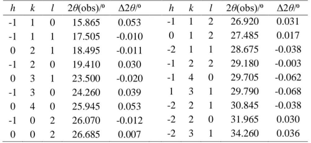
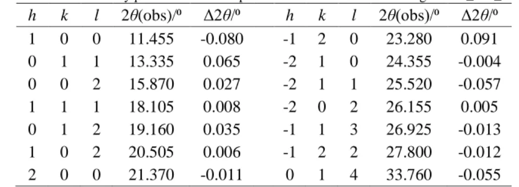
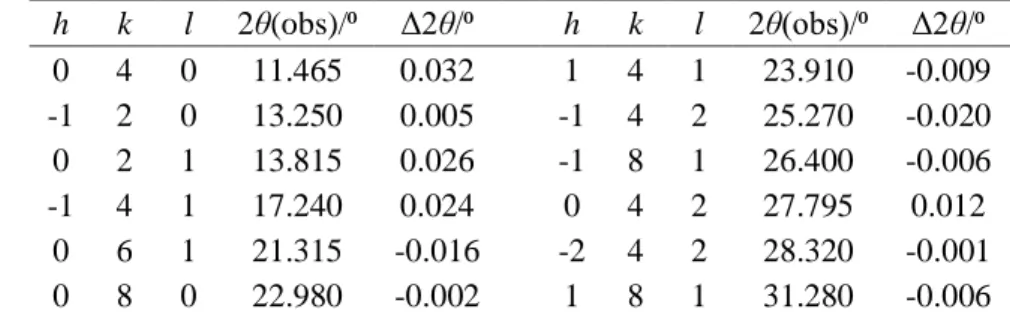
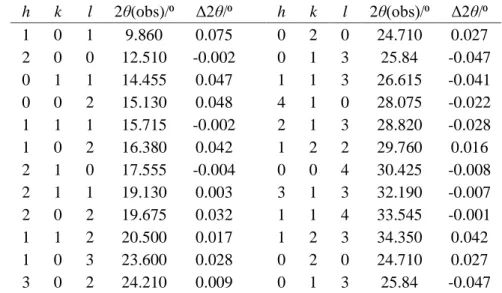
Table 2.1. Indexation of the X-ray powder diffraction pattern for HBA form I in the range of 7⁰ ≤ 2θ ≤ 35⁰...5 Table 2.2. Indexation of the X-ray powder diffraction pattern for HAP form I in the range of 7⁰ ≤ 2θ ≤ 35⁰. ...6 Table 2.3. Indexation of the X-ray powder diffraction pattern for HPP in the range of 7⁰ ≤ 2θ ≤ 35⁰. ...6 Table 2.4. Indexation of the X-ray powder diffraction pattern for HBP in the range of 7⁰ ≤ 2θ ≤ 35⁰. ...7 Table 2.5. Indexation of the X-ray powder diffraction pattern for HVP in the range of 7⁰ ≤ 2θ ≤ 35⁰. ...8 Table 2.6. Indexation of the X-ray powder diffraction pattern for HHP in the range of 7⁰ ≤ 2θ ≤ 35⁰. ...8 Table 3.1. Results obtained by DSC for, Tfus, Tmax, and ∆fusHmo of the studied molecules. ... 22
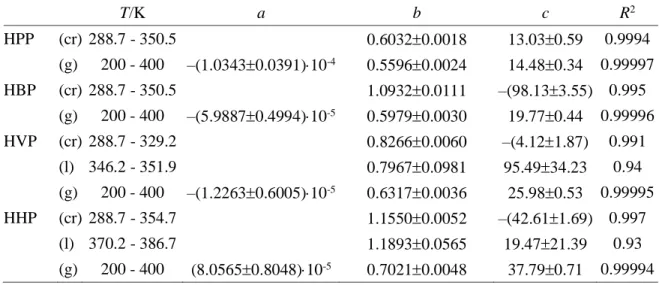
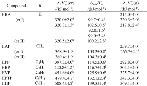
Table 3.2. Coefficients of the heat capacity obtained by equation (3.2) for the solid, liquid and gaseous states. ... 23 Table 3.3. Thermochemical data for 4-HOC6H4COR compounds (R = H, CH3, C2H5, n-C3H7,
n-C4H9, n-C5H11 and n-C6H13), at T = 298.15 K and po = 1 bar.a ... 25
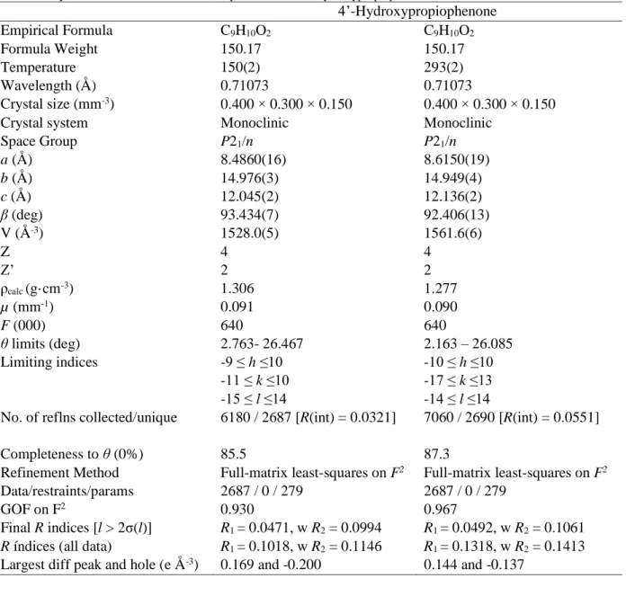
Table 3.4. Crystal data and structure refinement parameters for 4’-hydroxypropiophenone at 150 and 293 K. ... 27 Table 3.5. Crystal data for form I of 4’-hydroxyvalerophenone obtained by single crystal X-ray available on literature.34 ... 31
Table 3.6. Crystal data and structure refinement parameters for 4’-hydroxyvalerophenone form II determined by single crystal X-ray diffraction at 296 K. ... 31 Table 3.7. Crystal data and structure refinement parameters for 4’-hydroxyheptanophenone determined by single crystal X-ray diffraction. ... 36 Table 3.8. Crystal Data for HBA, HAP, HVP at 298 K and HBP at 293 K. ... 39
xiv
Figure List
Figure 1.1. Molecular structure of ritonavir. ...2 Figure 1.2. Gibbs free energy variation as a function of temperature for a) a enantiotropic or b) monotropic system composed by two polymorphs (adapted from reference 15).The solid lines represent the Gibbs free energy of the two solid (cr I/ cr II) forms and the liquid state (liq). The dashed lines represent the enthalpy of the two solid (Hcr I/ Hcr II) forms and the liquid phase (Hliq).
The Tfus (I) and Tfus (II) represent the fusion temperature of the two solid forms. ...3
Figure 1.3.Molecules studied in this thesis: (a) 4-hydroxybenzaldeheyde; (b) hydroxyacetophenone; (c) hydroxypropiophenone; (d) hydroxybutirophenone; (e) 4’-hydroxyvalerophenone and (f) 4’-hydroxyheptanophenone. ...4
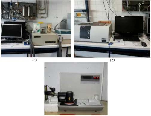
Figure 2.1. DSC apparatus used in this work: (a) DSC 7 from Perkin-Elmer, (b) DSC 204 F1 Phoenix from Netzch and (c) TA Instruments 2920 MTDSC. ... 10 Figure 2.2. (a) Detail of the two separated furnaces in DSC 7 from Perkin-Elmer and (b) scheme of the power compensation apparatus (adapted from reference 43): 1, cell; 2, reference furnace; 3, sample furnace; 4, reference crucible; 5, sample crucible; 6, heat source 7, temperature sensor; and 8, sample. ... 11 Figure 2.3. (a) Image of Netzch DSC 204 F1 Phoenix furnace and (b) the TA Instruments 2920 MTDSC furnace. (c) Schematic of a disk type heat flux apparatus (adapted from reference 43): 1, block furnace; 2, reference crucible; 3, sample crucible; 4, temperature sensors; and 5, sample. ... 11 Figure 2.4. Thermogram of an endothermic event where Ton, corresponds to the onset temperature,
Tmax, the peak temperature and A to the area of the curve, that is proportional to the standard
specific enthalpy of the process. ... 12 Figure 2.5. Schematic representation of the experimental procedure required to determine heat capacity by DSC using the dynamic mode. The gray curve indicates the temperature program used in the three independent runs (black curves): i) blank experiments (zero line) performed using two empty crucibles; ii) run performed using a reference compound; and iii) experiment with a compound sample. Δϕ0, ΔϕR,ΔϕS corresponds to the heat flow rate difference of the zero
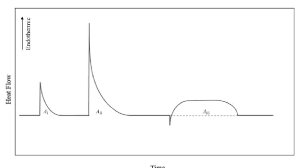
line, reference and sample, respectively. ... 14 Figure 2.6. (a) Picture of the Calvet microcalorimeter used in this work, with (b) a close up of the wells. ... 14 Figure 2.7. Schematic of the Calvet microcalorimeter (adapted from reference 48 and 49): 1, 1’, 2 and 2’, wells, 3, microcalorimetric element, 4, furnace, 5, thermocouples, 6¸measuring cell, 7, brass cylinder, 8, Teflon tube, 9, glass cell, 10, brass piece, 11, Manganin wire resistance, 12, drop furnace, 13, sample, 14, movable pin, 15, lid with platinum resistance sensor, 16, funnel, 17, inlet connected to a vacuum/inert gas system. ... 15 Figure 2.8. Scheme of a Calvet drop experiment: Ai, N2 introduction, Aii, sample drop, Aiii,
sublimation/vaporization experiment. ... 17 Figure 2.9. Schematic representation of the auxiliary measuring curves required for the computation of the molar enthalpies of sublimation or vaporization of the compounds: Ag,
represents the area associated to the energy necessary to heat the glass from 298.15 K to the sublimation/vaporization temperature; Ab, is the area of the thermal effect associated with
pumping of the N2 atmosphere in the cells; and Ac represents the area associated with the
xv Figure 3.1. Typical DSC measuring curves obtained for HPP, HBP, HVP and HHP. All the curves were previously normalized with the mass of the respective sample. ... 22 Figure 3.2. Heat capacities determinations for solid state, Cp,mo (cr) which are illustrated as full
round markers while the heat capacities determinations for liquid state, Cp,mo (liq) are represented
as empty round markers. The grey markers correspond to HPP, the yellow markers to HBP, the blue markers to HVP and the purple markers for HHP. ... 23 Figure 3.3. Standard molar enthalpies of sublimation for the compounds studied at 298.15 K, as function of the number of carbon (nc) atoms in the alkyl side chain. ... 25
Figure 3.4.Structure obtained for 4’-hydroxypropiophenone using the software Mercury40 (a)
geometry of the conformer and (b) the hydrogen bonding displayed by the molecule. These images apply for both structures determined at different temperatures. ... 27 Figure 3.5. Crystal packing of 4’-hydroxypropiophenone obtained using the software Mercury.40
... 28 Figure 3.6. Results of the DSC experiments for HVP performed in the temperature range 153 K to 453 K using TA Instruments 2920 MTDSC. The blue line corresponds to the initial form I sample and to the first cooling/heat cycle. The orange curve, corresponds to HVP form II obtained after crystallization from melt. ... 29 Figure 3.7. Hot stage polarized optical microscopy images showing the crystallization of the new HVP polymorph (form II) from melt and its subsequent fusion: (a) isotropic liquid at 353 K (250×); (b) initial stages of crystallization at 298 K (250×); (c) the material at 283 K, after complete crystallization (250×); (d) form II further cooled to 263 K (500×); (e) form II undergoing melting at 328 K, after being heated from 263 K (500×). ... 30 Figure 3.8. Schematic representation of the Gibbs energy and enthalpy versus temperature phase diagram highlighting the monotropic relationship of the HVP polymorphic system. ... 30 Figure 3.9. Structures obtained for 4’-hydroxyvalerophenone at room temperature using the software Mercury40: (a) geometry obtained for form I presenting a Z conformation and (b)
obtained for form II showing a E conformation. ... 32 Figure 3.10. Crystal packing of 4’-hydroxyvalerophenone form I obtained from available literature34 using the Mercury software.40 ... 33
Figure 3.11. Crystal structure of 4’-hydroxyvalerophenone form II using the Mercury software.40
(a) C1
1(8) chains with the molecules all parallel to each other; (b) crystal packing with stacking
of antiparallel chains. ... 33 Figure 3.12. Comparison of the X-ray powder diffraction (XRPD) patterns of HVP: (a) simulated from single crystal X-ray diffraction data previously reported (form I)34 (b) obtained for the
starting material of the DSC and HSM experiments (form I); (c) recorded for the material crystallized from the melt (form II). ... 33 Figure 3.13. Results of the DSC experiments for HHP performed on the temperature range 165 K to 453 K using TA Instruments 2920 MTDSC. A close up of the identified phase transition is also displayed. ... 34 Figure 3.14. Hot stage polarized optical microscopy images showing the cooling where the phase transition was not detected and subsequent heating of HHP until the fusion process starts: (a) crystalline sample at 213 K (250×); (b) crystalline material after the phase transition at 183 K (250×); (c) crystalline material at 323 K (250×); (d) crystalline material starting to melt at 368 K. ... 35 Figure 3.15. Structure obtained for 4’-hydroxyheptanophenone using the Mercury software40
xvi Figure 3.16. Packing motif C1
1(8) growing in a herringbone form of 4’-hydroxyheptanophenone
obtained through single crystal X-ray diffraction at 150 K using the Mercury software.40 ... 37
Figure 3.17. Crystal packing chain of 4’-hydroxyheptanophenone obtained through single crystal X-ray diffraction at 190 K using the Mercury software.40 ... 37
Figure 3.18. Molecular structure of 4’-hydroxyheptanophenone (a) and C1
1(8) chain in
herringbone form in crystal packing obtained through single crystal X-ray diffraction at 220 K using the Mercury software.40 ... 37
Figure 3.19. Molecular (a) and crystal packing motif (b)of 4’-hydroxyheptanophenone obtained through single crystal X-ray diffraction at 293 K using the Mercury software.40 ... 38
Figure 3.20. Crystal stacking of the parallel chains of 4’-hydroxyheptanophenone (a) at 190 K and (b) 220 K. ... 38 Figure 3.21. Overlay of the molecular structures obtained for 4’-hydroxyheptanophenone at 150 K (gray), 190 K (orange), 220 K (pink) and 293 K (green). ... 38 Figure 3.22.Crystal packing motif for 4-hydroxybenzaldeheyde (a) form I, (b) form II, 4’-hydroxyacetophenone (a) form I, (b) form II and 4’-hydroxybutyrophenone. ... 39
xvii
List of Abbreviations
HBA 4-hydroxybenzaldeheyde HAP 4’-hydroxyacetophenone HPP 4’-hydroxypropiophenone HBP 4’-hydroxibutyrophenone HVP 4’-hydroxyvalerophenone HHP 4’-hydroxyheptanophenone HPTP 4’-hydroxyhexanophenoneHPLC-ESI/MS High performance liquid chromatography electrospray mass spectrometry
1H NMR Proton nuclear magnetic resonance
DRIFT Diffuse reflectance infrared fourier-transform SCXRD Single crystal X-ray diffraction
XRPD X-ray powder diffraction
HSM Hot stage microscopy
DSC Differential scanning calorimetry δ Chemical deviation, ppm in 1H NMR
𝑣̃ Wavenumber, cm-1 in DRIFT
𝑣 Stretching vibrations in DRIFT
δ Bending vibrations in DRIFT
∆fusHmo Standard molar enthalpy of fusion ∆vapHmo Standard molar enthalpy of vaporization ∆subHmo Standard molar enthalpy of sublimation ∆fHmo Standard molar enthalpy of formation Δfusho Standard specific fusion enthalpy of fusion
Δvaph Specific fusion enthalpy of vaporization
Δsubh Specific fusion enthalpy of sublimation
Cp,mo Standard molar heat capacity
Δϕ Heat flow
M Molar mass
m Sample mass
T Temperature
Tfus Fusion temperature
Ton Starting temperature of a peak in a thermal event in a DSC experiment
Tmax Maximum temperature of a peak in a thermal event in a DSC experiment
Ti Initial temperature
Tf Final temperature
h k l Miller indices
a Unit cell vector a length b Unit cell vector b length c Unit cell vector c length
β Angle between vector a and c in the unit cell
V Volume of the unit cell
ρcalc Calculated density of the compound
Z Number of molecules in the unit cell
1
1. Introduction
Many of the organic materials prepared in industry (particularly the pharmaceutical) are obtained in the solid state (e.g. pills, capsules). Solids exist in two different forms: amorphous or crystalline. The difference between these forms is that the crystalline materials correspond to an organized state, while in the amorphous case, the molecules are in a disordered state.1 It was in
the very beginning of the 19th century that scientists became aware that crystalline solids could
show more than one packing arrangement. First for inorganic compounds2 and later for organic
molecules.3 Nowadays, it is well known that many organic molecular compounds can often exist
in several crystal forms.4-7 The ability of a given compound to present more than one crystal
structure (i.e. unit cell parameters, volume and density) is known as polymorphism. 8-10 Different
polymorphs should be treated as different materials, since they can exhibit dissimilar physical proprieties (e.g. color, fusion point and solubility).8, 11-12 The study of polymorphism and related
phenomena led to concepts such as conformational polymorphism (i.e different crystal packings that result from a molecular conformation change), solvatomorphism (i.e. the crystal structures that contain solvent molecules) or co-crystallization (i.e. crystal structures formed from more than one component). These classifications, however, have been subject to some debate.10, 13
From an industrial point of view, the fact that each polymorph corresponds to a different material allows to select the crystalline form that presents more suitable properties for a given application.14 However, control over polymorphism is a difficult task, since new forms can appear
if slight modifications are performed to the manufacturing process.5 Thus, tight control over the
production procedures is extremely important in several industries, such as explosives, dyes and pharmaceuticals.15-18 The lack of polymorphism control, for example, in the pharmaceutical
industry can cause health hazard situations, as illustrated by the well-known case of ritonavir. 19-20
Ritonavir (C37H48N6O5S2, CAS number:155213-67-5, Figure 1.1) is a protease inhibitor for
the treatment of acquired immunodeficiency syndrome (AIDS), discovered in 1992. The commercial launch began in 1996 under the name ‘Norvir’ with two different formulations: as an oral liquid or as semi-solid capsules. Both formulations were based on ritonavir in ethanol/water solutions.19 The International Conference on Harmonization of Technical Requirements of
Registration of Pharmaceuticals for Human Use (ICH) guidelines stated that when a drug product is commercialized in solution there is no need to control the crystal form. Thus, only one crystal form was identified during the development process for the compound.19 It was until two years
later that the drug began to precipitate in the capsules, which led to an investigation that identified a new polymorph, which was much less soluble than the original form. In the following weeks this new form appeared during the formulation process and on the bulk drug.19 Due to this fact,
the manufacture of Norvir semi-solid capsules stopped. Also, the liquid Norvir formulation could not be stored at low temperature due to the risk of crystallization. This led to a serious problem on the supply of this lifesaving drug until a new formulation could be developed.19-21
2 HO N H O N S H N O O N H N O S N
Figure 1.1. Molecular structure of ritonavir.
From an academic point of view, polymorphism can be used to investigate how intermolecular interactions, such as hydrogen bonds and Van der Waals forces can influence the different crystalline packing. The fact that this phenomenon is mainly controlled by these forces, explains why these structures can be prepared through different methods (e.g. cooling of melts, condensation of vapors).10 Crystal engineering strategies rely on the understanding of these
interactions to design molecular solids in view of specific applications. One of the most used methods in polymorphism screening is crystallization from solution under different conditions (e.g. different solvents).10, 22 This also allows to investigate the different mechanisms of
crystallization, in which the hydrogen bonds can play an important role.22-23
Different polymorphs can often coexist at a given temperature, but with time, they will evolve to the most stable form in the absence of kinetic factors. The relative thermodynamic stability of two different forms and the driving force for a spontaneous transformation at constant temperature and pressure is determined by the difference in Gibbs energy (∆G) between the polymorphs as
∆G=∆H-T∆S
where ΔH is the enthalpy difference between the two phases, T is the temperature and ΔS is the entropy change between the two phases, that can be related, in part, to differences in disorder and lattice vibrations in the polymorphs.10, 24 According to the ΔG value there are three possibilities:
i) if the value is negative, the transformation will occur spontaneously unless its hindered by a kinetic barrier; ii) if equal to zero the system is in equilibrium because the Gibbs energy of the two phases is the same, so both phases can coexist at the same temperature and pressure conditions; iii) if positive the reverse transformation will tend to spontaneously occur, in the absence of kinetic barriers.10, 24
One way to express quantitative information about the relative stability of polymorphs is by plotting a phase diagram of the Gibbs free energy (G) as a function of temperature (T). Figure 1.2 shows typical plots for a polymorphic system composed by two polymorphs. In this figure, each intersection between two Gibbs free energy lines corresponds to a condition where two different phases can coexist in equilibrium. Hence, Tfus (I), Tfus (II) represent the temperature at which the
lines of form I and form II intercept that of the liquid, respectively, so that the melting can occur. An additional interception is noted in Figure 1.2a at Ttrs (II → I), between the curves of crystal I
and II. At this point, an inversion of stability is observed between the two polymorphs and a (1.1)
3
(a) (b)
Figure 1.2. Gibbs free energy variation as a function of temperature for a) a enantiotropic or b) monotropic system
composed by two polymorphs (adapted from reference 15).The solid lines represent the Gibbs free energy of the two solid (cr I/ cr II) forms and the liquid state (liq). The dashed lines represent the enthalpy of the two solid (Hcr I/ Hcr II)
forms and the liquid phase (Hliq). The Tfus (I) and Tfus (II) represent the fusion temperature of the two solid forms. solid-solid phase transition can occur. In this particular case, because Ttrs (II → I) is located before
the melting temperature of the two phases, the system is called enantiotropic. In contrast, in Figure 1.2b, no phase transition is observed and, for this reason, form I is always more stable than form II up to melting. In this case, the system is called monotropic. Although, not related by a phase transition, it should be mentioned that, on thermodynamic grounds, if form II is prepared, it will tend to transform into form I at any temperature. This illustrates the importance of the knowledge of the thermodynamic relationship between different crystal phases, during production and storage of solid materials.11, 15, 25
In order to determine if a polymorphic system is either monotropic or enantiotropic, the rules recommended by Burger and Ramberger,26 can be used. The most used rules are:
Heat of transition rule: if an endothermic phase transition between two polymorphs is observed, then the thermodynamic transition point lies at or below this temperature. In this case, the polymorphs are enantiotropically related. On the other hand, the polymorphs are monotropically related if an exothermic transition is observed at a given temperature and no phase transition occurs at a higher temperature.
Heat of fusion rule: the system is usually enantiotropic, if the polymorph with the higher temperature of fusion has the lowest enthalpy of fusion. If this does not occur, the system is monotropic. This rule can fail if the melting points of the polymorphs differ by more than 30 K.
Density rule: the most stable polymorph will show the highest density, due to the stronger intermolecular Van der Waals interactions. This rule is based on Kitaigorodskii’s principle of close packing structures and for non-hydrogen bonded systems at 0 K.27
The investigation of polymorphic systems has been one of the main topics of research addressed at the Molecular Energetics Group of Faculdade de Ciências da Universidade de Lisboa, during the last years. The study of the structure/energetic relations that are responsible for the occurrence of polymorphism in organic crystalline materials has been one of the main goals. Good examples of this work, can be found in the investigation of the polymorphic systems of 1-(hydroxyphenyl)ethan-1-one (4’-hydroxyacetophenone, HAP; Figure 1.3b) and 4-hydroxybenzaldeheyde (HBA; Figure 1.3a).28-30 Both compounds exhibit two polymorphs that
are enantiotropically related and, in the case of HAP, three hydrates were identified so far.31 Given
the similarity between these molecules (an hydrogen atom in HBA is replaced in HAP for a methyl group; Figures 1.3a-b), and their identical ability to form polymorphs with several common features (packing and hydrogen motifs), it became interesting to check how the increase
4 of the side alkyl chain (that considerably changes the Van der Waals ability of the molecules), can modify the packing features and polymorphs propensity in the 4-hydroxybenzoyl family (Figure 1.3). Thus, it became pertinent to extend the previous energetic and polymorph screenings performed to HBA and HAP, to the following compounds: 1-(4-Hydroxyphenyl)propan-1-one (4’-hydroxypropiophenone, HPP, HOC6H4COC2H5); 1-(4-Hydroxyphenyl)butan-1-one
(4’hydroxybutirophenone, HBP, HOC6H4COC3H7); 1-(4-Hydroxyphenyl)pentan-1-one
(4’-hydroxyvalerophenone, HVP, HOC6H4COC4H9) and 1-(4-Hydroxyphenyl)heptan-1-one
(4’-hydroxyheptanophenone, HHP, HOC6H4COC6H13).
The work described in this thesis, presents the first steps towards the development of a comprehensive study of polymorphism in the 4-hydroxybenzoyl family. Two different topics were addressed: i) the use of differential scanning calorimetry (DSC), Calvet-drop microcalorimetry and theoretical methods, to evaluate enthalpies of fusion, sublimation, vaporization and formation in the gaseous and solid phases of the compounds; and ii) the use of single crystal X-ray diffraction and X-ray powder diffraction in combination with DSC results, as tools to identify and characterize the new polymorphic forms of these materials.
(a) (b) (c)
(d) (e) (f)
Figure 1.3.Molecules studied in this thesis: (a) 4-hydroxybenzaldeheyde; (b) hydroxyacetophenone; (c)
4’-hydroxypropiophenone; (d) 4’-hydroxybutyrophenone; (e) 4’-hydroxyvalerophenone and (f) 4’-hydroxyheptanophenone.
5
2. Materials and Methods
In this chapter the characterization of all materials used in this work is presented. Also described are the experimental techniques used in the characterization and in the thermodynamic measurements, with the more relevant explained in detail. Finally, a brief summary of the methodologies behind the computational calculations performed by Dr. Filipe Agapito is given.
2.1. Materials
Absolute ethanol p.a supplied by Chem-Lab and ethyl acetate (mass fraction 0.997) supplied by Fluka were used without further purification.
4-Hydroxybenzaldeheyde (HBA, CAS number: 123-08-0) supplied by Aldrich with a mass fraction of 0.98 was purified by sublimation at 350 K and 1.33 Pa. No impurities were detected by Gas Chromatography-Mass Spectrometry (GC-MS) analysis. Proton nuclear magnetic resonance (1H NMR) analysis (400 MHz, CDCl
3): δ = 9.87 (s, CH, 1H), 7.83 (d, CH, 2H), 6.98
(d, CH, 2H), 6.15 (s, OH, 1H). Diffuse reflectance infrared Fourier-transform (DRIFT) analysis (KBr, main peaks): 𝑣 ̃ = 3163 (vO-H); 2962 (vC-H); 1660 (vC=O); 1589 (vC-C, in ring). The 1H NMR
and DRIFT spectra are available in the Supporting Information, section A. The powder pattern recorded at 298±2 K was indexed (Table 2.1) as monoclinic, space group P21/c, a = 6.4541(20)
Å, b = 13.7532(36) Å, c = 7.0286(20) Å, β = 108.19(3)⁰, which is in agreement with previously published results from single crystal X-ray diffraction (SCXRD)32: monoclinic, space group
P21/c, a = 6.453(5) Å, b = 13.810(8) Å, c = 7.044(6) Å, β = 107.94(9)⁰. The obtained
diffractograms are shown in the Supporting Information, section A.
4’-Hydroxyacetophenone (HAP, CAS number: 99-93-4) supplied by Fluka with a mass fraction of 0.98 was purified by sublimation at 368 K and 1.3 Pa. Elemental analysis for C8H8O2:
expected C 70.57%, H 5.92%; found C 70.68±0.14%, H 5.95±0.06%. No impurities were detected by high performance liquid chromatography electrospray mass spectrometry (HPLC-ESI/MS).
1H NMR analysis (400 MHz, CDCl
3): δ = 7.92 (d, CH, 2H), 7.07 (s, OH, 1H), 6.93 (d, CH, 2H),
2.58 (s, CH3, 3H). DRIFT analysis (KBr, main peaks): 𝑣 ̃ = 3174 (vO-H); 2991 (vCH3); 1643 (vC=O);
1578 (vC-C, in ring), 1363 (δ CH3). The 1H NMR and DRIFT spectra are available in the Supporting
Information, section A. The powder pattern recorded at 298±2 K was indexed (see Table 2.2) as monoclinic, space group P21/c, a = 8.6153(59) Å, b = 14.9708(145) Å, c = 12.1601(178) Å, β =
92.320(249)⁰, which is in agreement with previous published results of SCXRD29 obtained at the
Table 2.1. Indexation of the X-ray powder diffraction pattern for HBA form I in the range of 7⁰ ≤ 2θ ≤ 35⁰.
h k l 2θ(obs)/⁰ Δ2θ/⁰ h k l 2θ(obs)/⁰ Δ2θ/⁰ -1 1 0 15.865 0.053 -1 1 2 26.920 0.031 -1 1 1 17.505 -0.010 0 1 2 27.485 0.017 0 2 1 18.495 -0.011 -2 1 1 28.675 -0.038 -1 2 0 19.410 0.030 -1 2 2 29.180 -0.003 0 3 1 23.500 -0.020 -1 4 0 29.705 -0.062 -1 3 0 24.260 0.039 1 3 1 29.790 -0.068 0 4 0 25.945 0.053 -2 2 1 30.845 -0.038 -1 0 2 26.070 -0.012 -2 2 0 31.965 0.030 0 0 2 26.685 0.007 -2 3 1 34.260 0.036
6
Table 2.2. Indexation of the X-ray powder diffraction pattern for HAP form I in the range of 7⁰ ≤ 2θ ≤ 35⁰.
h k l 2θ(obs)/⁰ Δ2θ/⁰ h k l 2θ(obs)/⁰ Δ2θ/⁰ 1 0 0 11.455 -0.080 -1 2 0 23.280 0.091 0 1 1 13.335 0.065 -2 1 0 24.355 -0.004 0 0 2 15.870 0.027 -2 1 1 25.520 -0.057 1 1 1 18.105 0.008 -2 0 2 26.155 0.005 0 1 2 19.160 0.035 -1 1 3 26.925 -0.013 1 0 2 20.505 0.006 -1 2 2 27.800 -0.012 2 0 0 21.370 -0.011 0 1 4 33.760 -0.055
same temperature: monoclinic, space group P21/c, a = 7.7200(15) Å, b = 8.3600(17) Å, c =
11.280(2) Å, β = 95.02(3)⁰. The obtained diffractograms are shown in the Supporting Information, section A.
4’-Hydroxypropiophenone (HPP, CAS number: 70-70-2) supplied by Aldrich with a mass fraction of 0.995, was purified prior to use by sublimation at 378 K and 1.3 Pa. Elemental analysis for C9H10O2: expected: C 71.98%, H 6.71%; C 71.82±0.03%, H 6.63±0.03%. No impurities were
detected by HPLC-ESI/MS. 1H NMR analysis (400 MHz, CDCl
3): δ = 7.92 (d, CH, 2H), 6.88 (d,
CH, 2H), 5.55 (s, OH, 1H), 2.96 (q, CH2, 2H), 1.22 (t, CH3, 3H). DRIFT analysis (KBr, main
peaks): 𝑣 ̃ = 3213 (vO-H); 2970 (vCH3); 1649 (vC=O); 1572 (vC-C, in ring), 1358 (δCH3, CH2). The 1H
NMR and DRIFT spectra are available in the Supporting Information, section A. The powder pattern recorded at 298±2 K was indexed (see Table 2.3) as monoclinic, space group P21/n, a =
8.6153(59) Å, b = 14.9708(145) Å, c = 12.1601(178) Å, β = 92.320(249)⁰, which is in agreement with results from SCXRD determined in this work at the same temperature (see Chapter 3, section 3.2): monoclinic, space group P21/n, a = 8.6150(19) Å, b = 14.949(4) Å, c = 12.136(2) Å, β =
92.406(13)⁰. The obtained diffractograms are shown in the Supporting Information, section A. 4’-Hydroxybutyrophenone (HBP, CAS number: 1009-11-6) provided by Tokyo Chemical Industry (TCI) with a mass fraction of 0.993, was previously purified by sublimation at 348 K and 3.5 Pa. Elemental analysis for C10H12O2: expected C 73.15%, H 7.37%; found C 73.27±0.2%,
H 7.45±0.1%. No impurities were detected by HPLC-ESI/MS. 1H NMR analysis (400 MHz,
CDCl3): δ = 7.91 (d, CH, 2H), 6.89 (d, CH, 2H), 5.70 (s, OH, 1H), 2.90 (t, CH2, 2H), 1.76 (q,
CH2, 2H), 1.00 (t, CH3, 3H). DRIFT analysis (KBr, main peaks): 𝑣 ̃ = 3367 (vO-H); 2962 (vCH3);
1655 (vC=O); 1579 (vC-C, in ring), 1365 (δCH3, CH2). The 1H NMR and DRIFT spectra are available
in the Supporting Information, section A. The powder pattern recorded at 298±2 K was indexed (see Table 2.4) as monoclinic, space group P21/c, a = 8.3013(38) Å, b = 30.9332(61) Å, c =
7.9059(22) Å, β = 116.87 (2)⁰, which is in agreement with previously published results single crystal X-ray diffraction33: monoclinic, space group P2
1/c, a = 8.2650(17) Å, b = 30.986(6) Å,
Table 2.3. Indexation of the X-ray powder diffraction pattern for HPP in the range of 7⁰ ≤ 2θ ≤ 35⁰.
h k l 2θ(obs)/⁰ Δ2θ/⁰ h k l 2θ(obs)/⁰ Δ2θ/⁰ 1 1 0 11.750 -0.100 0 2 2 18.810 0.013 -1 0 1 12.385 0.036 0 3 1 19.200 -0.012 -1 1 1 13.725 0.030 1 3 0 20.585 0.029 0 2 1 13.895 0.011 2 1 1 22.430 0.029 1 2 0 15.665 -0.011 -2 1 1 22.430 0.015 1 2 1 17.475 0.000 0 1 3 22.695 -0.032
7
Table 2.4. Indexation of the X-ray powder diffraction pattern for HBP in the range of 7⁰ ≤ 2θ ≤ 35⁰.
h k l 2θ(obs)/⁰ Δ2θ/⁰ h k l 2θ(obs)/⁰ Δ2θ/⁰ 0 4 0 11.465 0.032 1 4 1 23.910 -0.009 -1 2 0 13.250 0.005 -1 4 2 25.270 -0.020 0 2 1 13.815 0.026 -1 8 1 26.400 -0.006 -1 4 1 17.240 0.024 0 4 2 27.795 0.012 0 6 1 21.315 -0.016 -2 4 2 28.320 -0.001 0 8 0 22.980 -0.002 1 8 1 31.280 -0.006
c = 7.9200(16) Å, β = 116.94(3)⁰. The obtained diffractograms are shown in the Supporting Information, section A.
4’-Hydroxyvalerophenone (HVP, CAS number: 2589-71-1) provided by TCI with a mass fraction of 0.993 was previously purified by crystallization. A solution of 25 cm3 of ethanol was
saturated with HVP at 328 K. With the solution still warm, it was filtered into an Erlenmeyer flask, using Whatman Grade 1 qualitative filter paper. Subsequently the solution was stored in a cooler and kept at 255 K. Well-formed crystals were obtained in approximately 4 days. Through vacuum filtration using a sintered glass funnel, the crystals were separated from the initial solution and dried in air at 293±2 K. Elemental analysis for C11H14O2: expected C 74.13%, H 7.92%; found
C 74.33±0.05%, H 7.45±0.1%. No impurities were detected by HPLC-ESI/MS. 1H NMR analysis
(400 MHz, CDCl3): δ = 7.92 (d, CH, 2H), 6.91 (d, CH, 2H), 6.55 (s, OH, 1H), 2.93 (t, CH2, 2H),
1.71 (m, CH2, 2H), 1.40 (m, CH2, 2H), 0.94 (t, CH3, 3H). DRIFT analysis (KBr, main peaks): 𝑣 ̃
= 3221 (vO-H); 2933 (vCH3); 1645 (vC=O); 1587 (vC-C, in ring), 1344 (δCH3, CH2). The 1H NMR and
DRIFT spectra are available in the Supporting Information, section A. The powder pattern recorded at 298±2 K was indexed (see Table 2.5) as monoclinic, space group P21/c, a =
9.9881(45) Å, b = 10.4446(40) Å, c = 9.8792(45) Å, β = 107.52 (4)⁰, which is in agreement with prior published results obtained by SCXRD34 at the same temperature: monoclinic, space group
P21/c, a = 9.990(2) Å, b = 10.454(2) Å, c = 9.882(2) Å, β = 107.46(3)⁰. The obtained
diffractograms are shown in the Supporting Information, section A.
4’-Hydroxyheptanophenone (HHP, CAS number: 14392-72-4) provided by TCI with a mass fraction of 0.999, was used as received. Elemental analysis for C13H18O2: expected: C 75.69%, H
8.80%; found C 75.79±0.05%, H 8.94±0.07%. No impurities were detected by HPLC-ESI/MS.
1H NMR analysis (400 MHz, CDCl
3): δ = 7.91 (d, CH, 2H), 6.89 (d, CH, 2H), 5.70 (s, OH, 1H),
2.90 (t, CH2, 2H), 1.76 (q, CH2, 2H), 1.00 (t, CH3, 3H). DRIFT analysis (KBr, main peaks): 𝑣 ̃ =
3305 (vO-H); 2922 (vCH3); 1662 (vC=O); 1585 (vC-C, in ring), 1345 (δCH3, CH2). The 1H NMR and
DRIFT spectra are available in the Supporting Information. The powder pattern recorded at 298±2 K was indexed (see Table 2.6) as orthorhombic, space group Pnma, a = 14.1372(32) Å, b =
7.2079(14) Å, c = 11.7393(15)⁰, which is in agreement with results from SCXRD determined in this work at the same temperature (see Chapter 3, section 3.2): orthorhombic, space group Pnma,
a = 14.158(3) Å, b = 7.2246(17) Å, c = 11.762(3)⁰. The obtained diffractograms are shown in the Supporting Information, section A.
8
Table 2.5. Indexation of the X-ray powder diffraction pattern for HVP in the range of 7⁰ ≤ 2θ ≤ 35⁰.
h k l 2θ(obs)/⁰ Δ2θ/⁰ h k l 2θ(obs)/⁰ Δ2θ/⁰ 1 0 0 9.300 0.023 -2 2 1 25.020 0.075 0 1 1 12.655 0.012 -2 2 0 25.315 0.026 0 2 0 16.945 -0.019 0 3 1 27.220 -0.067 1 1 1 17.380 0.070 -2 2 2 27.995 -0.057 -1 0 2 18.295 -0.017 -3 1 0 29.355 -0.024 0 0 2 18.940 0.117 0 1 3 29.675 -0.007 0 2 1 19.410 -0.008 -2 1 3 30.235 0.030 -1 1 2 20.275 0.073 -2 3 1 31.595 0.060 -2 1 0 20.525 0.046 -1 2 3 31.925 -0.193 -2 0 2 22.220 0.045 -3 2 0 32.845 -0.145 1 2 1 22.840 0.071 -2 2 3 33.725 -0.012 -2 1 2 23.745 -0.027 -2 3 2 34.185 0.092
Table 2.6. Indexation of the X-ray powder diffraction pattern for HHP in the range of 7⁰ ≤ 2θ ≤ 35⁰.
h k l 2θ(obs)/⁰ Δ2θ/⁰ h k l 2θ(obs)/⁰ Δ2θ/⁰ 1 0 1 9.860 0.075 0 2 0 24.710 0.027 2 0 0 12.510 -0.002 0 1 3 25.84 -0.047 0 1 1 14.455 0.047 1 1 3 26.615 -0.041 0 0 2 15.130 0.048 4 1 0 28.075 -0.022 1 1 1 15.715 -0.002 2 1 3 28.820 -0.028 1 0 2 16.380 0.042 1 2 2 29.760 0.016 2 1 0 17.555 -0.004 0 0 4 30.425 -0.008 2 1 1 19.130 0.003 3 1 3 32.190 -0.007 2 0 2 19.675 0.032 1 1 4 33.545 -0.001 1 1 2 20.500 0.017 1 2 3 34.350 0.042 1 0 3 23.600 0.028 0 2 0 24.710 0.027 3 0 2 24.210 0.009 0 1 3 25.84 -0.047
2.2.General Methods
Elemental analyses (C, H) were performed by Laboratório de Análises of Instituto Superior Técnico (LAIST) of Universidade de Lisboa (UL), using a Fisons Intruments EA1108 apparatus. The analyses were made in duplicate, so that the reported values correspond to their average, and the uncertainties are twice the mean deviation.
High performance liquid chromatography electrospray mass spectrometry (HPLC-ESI/MS) was performed at Centro de Química Estrutural, Instituto Superior Técnico (CQE-IST), UL, using a HPLC Dionex Ultimate 3000, consisting of a binary pump HPG3200, an autosampler WPS300, a diode array UV absorbance detector (DAD 3000) set to 254 nm and a column oven TCC3000. This apparatus was coupled in line to a LCQ Fleet ion trap mass spectrometer equipped with an ESI ion source (Thermo Scientific). Methanolic solutions of the compounds were injected into a Phenomenex Luna C18 (2) column (150 mm × 2 mm, 3 μm) at 308 K, by a Rheodyne injector with a 0.02 cm3 loop. Separation was performed at a flow rate of 3.33 × 10⁻³ cm-3∙s-1, with a 300
s linear gradient from 50 to 80% (v/v) of acetonitrile in 0.1% of formic acid in water followed by a 600 s linear gradient until a 100% of acetonitrile. Afterwards, the column was re-equilibrated
9 with 50% acetonitrile in 0.1% (v/v) of formic acid in water for a period of 600 s. The mass spectrometer was operated in the ESI (+/-) ion modes, with optimized parameters: ion spray voltage, ±4.5 kV; capillary voltage, 16/-18 V; tube lens offset, -63/58 V, sheath gas (N2), 80
arbitrary units; auxiliary gas, 5 arbitrary units; capillary temperature, 573 K. The mass spectra correspond to an average of 20 to 35 scans, recorded in the range between 50 to 500 Da. The data acquisition and processing were carried out using the Xcalibur software.
Proton nuclear magnetic resonance spectra (1H NMR) were obtained at room temperature in a
Bruker Ultrashield 400 MHz instrument. The solvent used was deuterated chloroform (CDCl3;
Aldrich, 99.8 atom % D) with 1% (v/v) TMS. It was stored over molecular sieves (Aldrich, 4 Å, 8-12 mesh), which were activated prior to use at approximately 0.1 Pa and 493 K during at least 6 h.
Diffuse reflectance infrared Fourier-transform (DRIFT) spectroscopy was performed in a Nicolet 6700 spectrometer (Thermo Electron Corp., Madison, WI) equipped with a deuterated triglycine sulfate (DTGS) detector (4000 – 400 cm-1) and a Smart Diffuse Reflectance (SDR) kit
(Thermo Electron Corp.). The spectra were collected with a resolution of 2 cm-1, using 528 scans
for the sample and background experiments. The background spectra were recorded with pure KBr (Aldrich, FTIR grade) and the samples were prepared by mixing KBr with the compound in appropriate weight proportions to obtain spectral absorbance in the range of applicability of the Kubelka-Munk transformation.35
Single crystal X-ray diffraction (SCXRD) was performed at Laboratório de Cristalografia, CQE-IST-UL. The experiments were done at 167±2 K and 293 K, using a Bruker AXS-KAPPA APEX II and a D8 Quest area detectors diffractometers. The crystals were coated with Paratone-N oil and mounted on a Kaptan loop. A graphite-monochromated Mo Kα (λ = 0.71073 Å) radiation source running at 50 kV and 30 mA was used. An empirical absorption correction was enforced using Bruker SADABS36 and data reduction was done with Bruker SAINT37 program.
The structures were solved by direct methods with Bruker SHELXS38 and refined by
full-matrix-least-squares on F2 using SHELXL38 programs within WINGX-Version 2014.1.39 Non-hydrogen
atoms were refined with anisotropic thermal parameters. Hydrogen atoms were located in the density map and isotropic displacement parameters, Uiso(H), refined freely. Structural
representations were made using Mercury 3.840, and PLATON was used for the hydrogen bond
interactions.41
X-ray powder diffraction (XRPD) patterns were obtained on Philips X’Pert PRO apparatus equipped with an X’Celerator detector with automatic data acquisition (X’Pert Data Collector, v2.0b, software). The apparatus had a vertical goniometer (PW 3050/60). A Cu Kα radiation source was used. The tube amperage was 30 mA and the tube voltage 40 kV. The diffractograms were recorded at ~293 K in the range 7º < 2θ < 35º. Data was collected in the continuous mode, with a step size of 0.017º (2θ) and scan step times of 20 s. The samples were mounted on an aluminum sample holder. The indexation of the powder patterns was performed using the program Checkcell.42
Hot stage polarized optical microscopy (HSM) studies for HVP and HHP were carried out with an Olympus BX51 microscope equipped with a Linkam LTS360 liquid nitrogen-cooled cryostage and a Linkam TMS94 programmable temperature controller. The microstructure of the sample was monitored by taking microphotographs with an Olympus C5060 wide zoom camera. Images were recorded at selected temperatures with 250× or 500× magnification. The sample was placed between two microscope slides and inserted into the hot stage. It was then subjected to a temperature program analogous to that used in the DSC experiments, in the range 173 K to 393 K, using heating/cooling rates of 10 K∙min-1.
10
2.3. Differential Scanning Calorimetry
Differential scanning calorimetry (DSC) was used to assess the purity and evaluate the existence of polymorphism in the studied compounds. For this purpose, the samples were investigated for the occurrence of solid-solid phase transitions and the enthalpies and temperature of fusion determined. Three calorimeters were used (see Figure 2.1): a) a DSC 7 from Perkin-Elmer, which was operated above room temperature to determine enthalpies and temperatures of fusion; b) a the DSC 204 F1 Phoenix from Netzch, that was used to determine the heat capacities and to evaluate the existence of polymorphism in the temperature range 213 K to 475 K; and c) a temperature-modulated TA Instruments 2920 MTDSC apparatus, operated as a conventional DSC, that was used to perform additional polymorphism studies starting at 150 K.
The Perkin-Elmer DSC 7 is controlled by a TAC 7/DX thermal analysis unit, that is connected to a computer and operated with the Pyris V. 7.0 Software from Perkin-Elmer. This calorimeter is a power compensation DSC43-44 (see Figure 2.2.), where the cell (1) has two separated furnaces,
the reference furnace (2) and the sample furnace (3), in which the reference crucible (4) and the sample crucible (5) are placed, respectively. Each of these furnaces is equipped with a heat source (6) and a temperature sensor (7). The furnaces are controlled by two separated temperature systems, one for average temperature control and another for differential temperature control. The first system ensures that both the sample and the reference temperatures are increased at a programmed rate, β. When the sample experiences an endothermic (e.g. fusion) or exothermic (e.g. crystallization) transformation or a heat capacity change (e.g. glass transition), a temperature difference (ΔT) develops between the two furnaces. At this point, the differential temperature control system adjusts the power supplied to each of the furnaces to maintain ΔT as small as possible during the course of the experiment. Finally, the difference of the power supplied to the sample and the reference are converted to the heat flow rate, ∆ϕ.
(a) (b)
(c)
Figure 2.1. DSC apparatus used in this work: (a) DSC 7 from Perkin-Elmer, (b) DSC 204 F1 Phoenix from Netzch and
11 The Netzch DSC 204 F1 Phoenix and TA Instruments 2920 MTDSC apparatus are disc type heat flux differential scanning calorimeters. As represented in Figure 2.3, these instruments only have one block furnace (1) where the temperature is controlled by a computer. Inside this block, both the reference (2) and sample crucibles (3), are placed over two temperature sensors (4) on the supporting disk. During the experiment, if a thermal event occurs, it is identified by a difference in the temperature that develops between the two crucibles. This difference is then recorded and converted to a heat flow rate difference between the sample and the reference.
(a) (b)
Figure 2.2. (a) Detail of the two separated furnaces in DSC 7 from Perkin-Elmer and (b) scheme of the power
compensation apparatus (adapted from reference 43): 1, cell; 2, reference furnace; 3, sample furnace; 4, reference crucible; 5, sample crucible; 6, heat source 7, temperature sensor; and 8, sample.
(a) (b)
(c)
Figure 2.3. (a) Image of Netzch DSC 204 F1 Phoenix furnace and (b) the TA Instruments 2920 MTDSC furnace. (c)
Schematic of a disk type heat flux apparatus (adapted from reference 43): 1, block furnace; 2, reference crucible; 3, sample crucible; 4, temperature sensors; and 5, sample.
12 The temperature and energy scales of the calorimeters were calibrated, based on the fusion of standard substances (temperature and enthalpies of fusion). In the case of the Perkin-Elmer DSC 7, the calibration was performed using indium (Perkin-Elmer; mass fraction 0.99999, Tfus =
429.75 K), lead (Goodfellow, mass fraction 0.99995, Tfus = 600.61 K) and zinc (Perkin-Elmer;
mass fraction 0.99999, Tfus = 692.65 K). The calibration of the Netzch DSC 204 F1 Phoenix
apparatus was carried out using a calibration kit (6.239.2-91.3.00) containing samples of adamantane (Ttrs = 208.65 K), indium (Tfus = 429.75 K,), tin (Tfus = 505.05 K), bismuth (Tfus =
544.55 K), zinc (Tfus = 692.65 K) and cesium chloride (Tfus = 749.15 K). The TA Instruments
2920 MTDSC was calibrated using n-decane (Fluka, mass fraction > 0.998, Tfus = 243.75 K),
n-octadecane (Fluka, mass fraction 0.999, Tfus = 301.77 K), hexatriacontane (Fluka, mass fraction
>0.995, Tfus = 347.30 K), indium (TA Instruments, DSC standard, Tfus = 430.61 K) and tin (TA
Instruments, DSC standard, Tfus = 506.03 K). For all apparatus the calibration was periodically
verified by measuring the temperature and enthalpy of fusion of indium.
In a typical DSC experiment, the sample was sealed inside an aluminum crucible and weighted with a precision of ±0.1 μg, on a Mettler XP2U or a Mettler UMT2 ultra-micro balance. The crucibles (sample and reference) were placed on the disks (disk type heat flux DSC) or inside the furnaces (power compensated DSC). Each experiment involves the increase or decrease of the furnace(s) temperature at a constant rate, while recording the output signal of the calorimeter as a function of the temperature and time (Figure 2.4). It was assigned that positive heat flow rates correspond to endothermic effects while negative heat flow rates correspond to exothermic events. By using the apparatuses software, for each thermal event in the thermogram, the onset temperature, Ton, the peak temperature, Tmax, and the standard specific enthalpy, Δho, were
computed. When the process corresponded to the fusion of the compound, Ton was assigned as its
fusion temperature, Tfus.
The standard specific enthalpy was calculated from the area (A) of the curve corresponding to the thermal event and the standard molar enthalpy, ∆Hmo, of the process was determined by equation 2.1:
∆Ho = ∆ho × M in which M corresponds to the molar mass of the sample.
Figure 2.4. Thermogram of an endothermic event where Ton, corresponds to the onset temperature, Tmax, the peak
temperature and A to the area of the curve, that is proportional to the standard specific enthalpy of the process.
13 The determination of the enthalpies and temperatures of fusion were performed using the procedure described above on DSC 7 from Perkin-Elmer and performed under nitrogen (Air liquid N45) flow, at a rate of 30 cm3∙min-1. All the experiments were done with a heating rate of 5 K∙min -1. The temperature and heat flow were calibrated at the same heating rate as indium. The sample
masses used for these determinations were: HPP 1 to 4 mg; HBP 1 to 2 mg; HVP 3 to 7 mg; and for HHP 2 to 5 mg (see Supporting Information, section B).
The heat capacity measurements on HPP, HBP, HVP and HHP, as mentioned above, were carried out on the Netzch DSC 204 F1 Phoenix, using the dynamic mode.43 The experiments were
performed in a single temperature range and involved three different stages (Figure 2.5, gray curve): a fore period, where the system was maintained at the initial temperature, Ti, during 20
minutes; the main period, where the temperature was increased at a constant rate; and the after period, where the system was kept for 20 minutes at the final temperature, Tf.
A typical heat capacity determination involves three consecutive measurements using the same temperature program and the same set of crucibles (Figure 2.5): i) a blank experiment performed with two empty crucibles (zero line), ii) a run using a reference sapphire disk (Netzsch, ref. 6.239.2-91.5), placed in the sample crucible, and iii) a run performed with the sample. In all experiments, the reference crucible was left untouched. The crucibles were chosen so that, the difference in the mass between them when empty was less than 0.01 mg. During the described procedure the heating rates used were 5 K∙min-1 for HPP and HBP, and 2 K∙min-1 for HVP and
HHP. All runs were performed under a nitrogen stream (Air liquid N45), with a flow rate of 20 cm3∙min-1. The sample masses were: HPP 8 to 16 mg; HBP 3 to 6 mg; HVP 4 to 13 mg; and for
HHP 6 to 14 mg (see Supporting Information, section C). Sapphire (Netzch, ref.6.239.2-91.5; ~12mg), was used as the reference material This procedure was previously tested with benzoic acid in the range of 215 K to 345 K.45 The accuracies obtained at heating rates of 2 K∙min-1 and
10 K∙min-1 were 2% and 3%, respectively, taking as benchmark the adiabatic calorimetry data
previously reported by Furukawa et. al..46
In this work, the heat capacity values were computed with the Netzch Proteus Analysis Software V.6.1.0, using the option ‘Cp ratio method’. Through this method the molar heat capacity of the sample (S) at a given temperature is given by:43
Cp,mo (S)= k
M mβ∆ϕ
where m is the mass of the sample, ∆ϕ is the difference in the heat flow rate between the blank, Δϕ0, and the sample, ΔϕS, and k is a calibration factor obtained at the same temperature as:
k = Cp,m o (α-Al
2O3)L Cp,mo (α-Al
2O3)R
where Cp,mo (α-Al2O3)L corresponds to the heat capacity of sapphire reported in literature by Archer47 and C
p,m
o (α-Al
2O3)R is the molar heat capacity of sapphire obtained experimentally using equation 2.2, assuming k = 1 and ∆ϕ = ΔϕR – Δϕ0 with ΔϕR representing the heat flow recorded
with the sapphire reference.
(2.2)