Internship Report
Master in Civil Engineering an “Building Construction”
Design of the confined masonry building in Quito,
Ecuador
Anna Zhgun
Internship Report
Master in Civil Engineering an "Building Construction"
Design of the confined masonry building in Quito,
Ecuador
Anna Zhgun
Report developed under the supervision of Hugo Rodrigues, professor at the School of Technology and Management of the Polytechnic Institute of Leiria.
ii This page was intetionally left blank
iii
Dedication
To my mother, who with great humility, efforts and sacrifices, supported me in this hard journey, and that in the difficult moments she always calmed me down and encouraged to keep going, thank you for teaching me to dream and that everything is possible if it is done with effort and dedication.
To the teachers who contributed to my education as a student.
iv This page was intetionally left blank
v
Acknowledgements
I would like to thank my supervisor, Professor Hugo Rodrigues, for the patience, motivation, encouragement and advice he has provided throughout my time as his student. His guidance helped me in all the time of my study. His experience and knowledge that he is sharing with his students are priceless.
My sincere thanks also goes to Dario Bermudez who supported me throughout the study process, for always being willing to listen to me and help me at any time. I have been extremely lucky to have this opportunity to go to Ecuador for internship and to get acquainted with the culture and traditions of this amazing country.
I would like to express my sincerest thanks to all my family for their encouragement and that they believed in me.
Furthermore, I would like to thank all my friends in Ecuador, whom I knew before during our study at IPL and also new people that I met there. They were extremely kind and supportive.
vi This page was intetionally left blank
vii
Resumo
Este relatório refere-se ao trabalho realizado durante o meu estágio na empresa IDC Proyectos Integrales que aconteceu no Equador, Quito, de janeiro de 2018 a julho de 2018.
O Equador é um país que tem um alto risco sísmico, instabilidade dos solos, a grande probabilidade de deslizamentos de terra, subsidência, erupções vulcânicas, tsunamis. Portanto, este é um lugar muito desafiador para se trabalhar em Engenharia de Estruturas. Uma das formas de mitigar o risco sísmico é projetar e construir edifícios com elementos estruturalmente resistentes a sismos e também a reabilitação e reconstrução de edifícios já existentes que foram projetados antes da implementação dos códigos e regulamentos relevantes.
O estágio teve como foco uma experiência com uma análise sísmica de diferentes tipos de estruturas, tais como estruturas metálicas, estruturas de betão armado e edifícios de alvenaria. No entanto, para um desenvolvimento mais detalhado neste relatório, foi escolhido o prédio de alvenaria confinada, uma vez que é o tipo de contrução mais popular de construção na América Latina. Devido ao recente sismo que aconteceu no Equador em 16 de abril de 2016 com muitas vítimas e grande número de casas destruídas, os edifícios em alvenaria confinada poderiam ser uma boa alternativa que atenda à necessidade de construção de moradias e reconstrução devido ao baixo custo e baixa complexidade técnica de construção.
Este tipo de construção tem muitas vantagens, como isolamento acústico, térmico, disponibilidade do material, mas da mesma forma é muito vulnerável ao mencionado antes dos perigos da natureza e tem uma limitação de altura para a construção dependendo do risco sísmico.
Este trabalho apresenta a visão geral das estruturas de alvenaria e alvenaria confinada, suas características e comportamento durante os terremotos. E como um exemplo da experiência mundial e da aplicação de códigos locais, apresento neste relatório uma análise detalhada do edifício multifamiliar de alvenaria confinada de dois andares usando regulamentações equatorianas, colombianas e americanas. Além disso, o projeto é realizado com a ajuda do programa computacional ETABS 2016.
viii This page was intetionally left blank
ix
Abstract
This report refers to work completed during my internship with the company IDC Proyectos Integrales that took place in Ecuador, Quito from January, 2018 to July 2018.
Ecuador is a country that has a high seismic risk, instability of soils, the great probability of landslides, subsidence, volcanic eruptions, tsunamis and etc. So this is a very challenging place to work for structural engineers. The only way to mitigate the seismic hazard is to design and construct buildings with elements structurally earthquake resistant and also rehabilitation and reconstruction of already existing buildings that were designed before implementing the relevant codes and regulations.
During the internship I had an experience with a seismic analysis of different types of structures such as steel frames, arch trusses, concrete frames, masonry buildings. However, for the further development I have chosen the confined masonry building as the most popular type of the construction in Latin America. Due to the recent destructive earthquake that happened in Ecuador on April 16, 2016 with a lot of victims and great number of houses destroyed, buildings in confined masonry could be a good alternative that meets the need for housing construction and reconstruction because of the low cost and low technical complexity of construction.
This type of the construction has many advantages, like acoustic, thermal insulation, availability of the material, but at the same way it is very vulnerable to mentioned before nature hazards and it has a height limitation for the construction depending of the seismic risk.
This work presents the overview of the masonry and confined masonry structures, its characteristics and behavior during the earthquakes. And as an example of the worldwide experience and the local codes application I present in this report a detailed analysis for the 2-storey confined masonry multifamily building using Ecuadorian, Columbians and American regulations. Moreover the design is performed with a help of the computational program ETABS 2016.
x This page was intetionally left blank
xi
List of figures
Figure 1 3D View of the structure... 8
Figure 2 Conceptual model of the project ... 9
Figure 3 North and South Facades ... 10
Figure 4 East and West Facades ... 10
Figure 5 Sections B-B' and C-C' ... 10
Figure 6 Facades of the building ... 13
Figure 7 Stress-strain relationships for mortar, separated units and masonry panels ... 17
Figure 8 Failure due to shear ... 21
Figure 9 Cracking of masonry units produced by diagonal tension failure ... 21
Figure 10 Failure due to excessive vertical cracking caused by compression forces 22 Figure 11 Failure modes of masonry subject to direct tension ... 23
Figure 12 A comparison of RC frames with masonry infills (a), and confined masonry construction (b) ... 27
Figure 13 Mechanism of shear resistance for a confined masonry wall panel: 1) diagonal cracking in the masonry wall; 2) diagonal cracks have propagated from the wall into the tie-columns, and 3) shear failure of the RC tie-columns and the confined masonry wall panel ... 29
Figure 14 Critical regions in a confined masonry building: a general diagram showing critical regions in the RC tie-columns... 29
Figure 15 Confined masonry wall panel subjected to the combined axial load and bending: a) panel elevation and a typical cross-section; b) strain distribution, and c) internal force distribution. ... 30
Figure 16 Test specimens ... 34
Figure 17 Crack patterns ... 34
Figure 18 Reinforcement of the columns in the project ... 37
Figure 19 Typical seismic-resistant details: columns ... 39
Figure 20 Additional confinement for vertical reinforcement in the beam and tie-column joint region ... 41
Figure 21 Typical seismic-resistant details: beams ... 42
xii
Figure 23 Distribution of loads and stresses in a wall ... 45
Figure 24 Distribution of lateral loads in buildings: a) flexible, and b) rigid diaphragm ... 47
Figure 25 Deformation of the wall ... 48
Figure 26 Overturning moment ... 49
Figure 27 Lateral distortions of a building ... 50
Figure 28 Location of the land (Google maps) ... 52
Figure 29 Yaruquí territory ... 53
Figure 30 Topographic map ... 53
Figure 31 Seismic microzonification of the soils of the Quito metropolitan district . 56 Figure 32 Materials properties assigment in ETABS (concrete) ... 60
Figure 33 Materials properties assigment (masonry) ... 61
Figure 34 Locked rigging units placed on a rope for structural masonry ... 62
Figure 35 Wind load (ETABS) ... 64
Figure 36 Seismic design map ... 67
Figure 37 Shell element ... 74
Figure 38 Deformation of shell element: a) axial deformation; b) shear deformation; c) bending(Etabs Shear walls design manual, 2010) ... 74
Figure 39 Pier and sprandel forces in ETABS ... 75
Figure 40 Structure model in ETABS ... 75
Figure 41 Elastic seismic spectrum of accelerations that represents the design earthquake ... 83
Figure 42 Response spectrum function (Etabs) ... 84
Figure 43 Response spectrum load case (Etabs) ... 86
Figure 44 Mode 1. T=0.088 (Etabs) ... 87
Figure 45 Mode 2. T=0.074 (Etabs) ... 87
Figure 46 Mode 3. T=0.071 (Etabs) ... 88
Figure 47 Waffle Slab section ... 104
Figure 48 Waffle Slab characteristics from ETABS ... 105
Figure 49 Example of the construction of the two-way waffle slab ... 106
Figure 50 Critical section for one-way shear ... 107
Figure 51 Definition of Design Strips... 109
Figure 52 Plan of the slab with the strips. Layer A. 1st floor ... 109
xiii
Figure 54 Plan of the slab. 1st floor. Layer A. Top and bottom reinforcement ... 110
Figure 55 Plan of the slab. 1st floor. Layer B. Top and bottom reinforcement ... 111
Figure 56 Sections of the slab in X and Y directions ... 116
Figure 57 Detail where the interruption of the support in a continuous shoe is indicated when there are openings in the masonry. ... 118
Figure 58 Strip foundation example and its deformed shape ... 120
Figure 55 Typical reinforcement of the strip foundation ... 121
Figure 60 Location of the critical section ... 122
Figure 61 Geometrical parameters for calculation ... 123
Figure 62 Analytical methods for seismic design of shallow foundations ... 126
Figure 63 Displacements RS-X ... 137
Figure 64 Displacements RS-Y ... 137
Figure 65 Displacements Seismic X+e ... 138
Figure 66 Displacements Seismic X-e... 138
Figure 67 Displacements Seismic Y+e ... 139
Figure 68 Displacements Seismic Y-e ... 139
Figure 69 Facades 1-8, D-A ... 210
Figure 70 Facades 8-1, A-D ... 211
Figure 71 Plan 1st floor ... 212
Figure 72 Plan 2nd floor ... 213
Figure 73 Plan of the columns 1st floor... 214
Figure 74 Plan of the columns 2nd floor ... 215
Figure 75 Walls axis A and 1 ... 216
Figure 76 Walls axis B and 2 ... 217
Figure 77 Walls axis C and 3 ... 218
Figure 78 Walls axis D and 4 ... 219
Figure 79 Walls axis 5, 6, 7, 8 ... 220
Figure 80 Formwork plan of the slab ... 221
Figure 81 Slab reinforcement. Bottom layer Y ... 222
Figure 82 Slab reinforcement. Bottom layer X ... 223
Figure 83 Slab reinforcement. Top layer Y ... 224
Figure 84 Slab reinforcement. Top layer X ... 225
Figure 85 Slab reinforcement. Detailing ... 226
xiv
Figure 87 Slab reinforcement. Materials calculation ... 228
Figure 88 Confining columns ... 229
Figure 89 Confining beams ... 230
Figure 90 Plan of the foundation ... 231
Figure 91 Foundation. Sections ... 232
Figure 92 Foundation. Detailing ... 233
Figure 93 Foundation. Specification ... 234
xv
List of tables
Table 1 Parameters of the Bloques ... 9
Table 2 Compression resistance of different masonry units ... 16
Table 3 Minimum compression resistance by NEC ... 17
Table 4 Specimens details ... 33
Table 5 Maximum stirrups spacing in the confining elements ... 37
Table 6 Description of geomorphological units... 54
Table 7 Structural system of load-bearing walls ... 59
Table 8 Parameters of the structure ... 59
Table 9 Types of mortar, dosage and minimum resistance to compression at 28 days ... 62
Table 10 Dead loads ... 63
Table 11 Live loads + Hile load ... 64
Table 12 Load combinations ... 65
Table 13 Z-factor values depending on the seismic zone ... 68
Table 14 Design parameters ... 69
Table 15 Ecuadorian provinces and value of Z-factor ... 69
Table 16 Mass source ... 78
Table 17 Centers of mass and rigidity ... 78
Table 18 Weight of the structure ... 78
Table 19 Modal periods and frequencies (Etabs) ... 86
Table 20 Modal participating mass ratios (ETABS) ... 87
Table 21 Calculation of the coefficients Ct and Cw ... 89
Table 22 Maximum ∆ values, expressed as a fraction of the floor height ... 92
Table 23 Maximum ∆ values for the project obtained in Etabs ... 92
Table 24 Resistance reduction factor ... 94
Table 25 Slab reinforcement results from ETABS. 1st floor ... 111
Table 26 Slab reinforcement results from ETABS. 2nd floor ... 113
Table 27 Concrete slab design. Check of the maximum and minimum reinforcement area. 1st floor ... 115
Table 28 Concrete slab design. Minimum reinforcement area ... 115
xvi
Table 30 Dimensions and reinforcement of the strip foundations ... 120
Table 31 Design for compression axial load. Flexo-compression resistance neglecting the contribution of masonry ... 195
Table 32 Design shear wall in the direction parallel to the plane ... 198
Table 33 Verification for crushing ... 200
Table 34 Checking the confining elements in shear. Columns and Beams ... 202
Table 35 Design of the longitudinal steel of the confinement beam ... 206
xvii
Table of Contents
DEDICATION III ACKNOWLEDGEMENTS V RESUMO VII ABSTRACT IX LIST OF FIGURES XI LIST OF TABLES XVTABLE OF CONTENTS XVII
1 INTRODUCTION 2
1.1 Objectives 3
1.2 Internship report framework 4
2 INTERNSHIP OVERVIEW 6
2.1 Steel frames with arch trusses for sports facilities in the schools 7
2.2 Scout project 9
2.3 Two-stories residential house 13
3 MASONRY CONSTRUCTION 14
3.1 Types and construction processes 15
3.2 Elements that make up the masonry 16
3.3 Origin of the problems in the masonry 19
xviii
3.3.2 Horizontal seismic forces 19
3.3.3 Interaction between the seismic forces and the masonry 20 3.3.4 Faults in the calculation of the masonry structures 23
3.3.5 Differential settlements 24
3.3.6 Bad quality of materials 24
3.3.7 Behavior of load bearing masonry buildings 25
3.3.8 Compression forces 25
3.3.9 Shear 25
4 CONFINED MASONRY 26
4.1 Confined Masonry and Similar Building Technologies 27
4.2 Seismic behavior of confined masonry structure 27
4.2.1 Typical Collapse Modes of Confined Masonry Buildings 30
4.3 Wall-frame connection analysis 32
4.4 Reinforcement of the confining elements 35
4.4.1 Columns of confinement 35
4.4.2 Confining beams 39
5 ANALYSIS OF LATERAL AND VERTICAL FORCES OF THE STRUCTURE 44
5.1 Horizontal diaphragms 44
5.2 Deflexions in diaphragms and walls 45
5.3 Types of diaphragms 46
5.3.1 Flexible diaphragms 46
5.3.2 Rigid diaphragms 46
5.4 Stiffness of the walls 47
5.5 Overturning moment 48
5.6 Torsion 49
6 PROJECT 52
xix 6.1.1 Location 52 6.1.2 Climate 52 6.1.3 Surface 53 6.1.4 Topography 53 6.1.5 Relief 54 6.1.6 Geology 54 6.1.7 Volcanic risk 57 6.1.8 Seismic risk 57 6.2 Structural description 57 6.2.1 Materials 60 6.3 Design loads 63 6.3.1 Dead loads 63 6.3.2 Variable loads 64 6.3.3 Combinations 65
7 SEISMIC ZONES IN ECUADOR 66
7.1 Seismic analysis 68
7.2 Seismic parameters 69
8 ANALYSIS AND DESIGN OF THE BUILDING USING COMPUTATIONAL
PROGRAM 72
8.1 Building design in ETABS 73
9 DESIGN BASED ON FORCES (DBF) 76
9.1 General objectives and requirements 76
9.1.1 Design objectives 77
9.1.2 Requirements RDBF: internal forces 77
9.1.3 DDBF requirements: floor drifts 77
9.1.4 Weight of the building for seismic calculations (W) 78
9.2 Methods of the analysis for DBF 78
9.2.1 Static procedure 79
9.2.2 Dynamic procedures for calculating seismic forces 79 9.2.3 Representation and determination of the horizontal seismic load 80
xx
9.2.4 Procedure 1: spectral analysis 80
9.3 DBF calculation procedure 81
9.3.1 Steps of the method 81
9.3.2 Horizontal distribution of shear 81
9.3.3 Elastic spectrum horizontal accelerations design 82 9.3.4 Determination of the vibration period T 88 9.3.5 Ductility and seismic resistance reduction factor R 90
9.3.6 CALCULATION OF DRIFT 91
10 DETAILED DESIGN OF SEISMIC ANALYSIS OF CONFINED MASONRY 94
10.1 Scope 94
10.2 Values of the resistance reduction factor 94
10.3 Design hypothesis 94
10.4 Design for compression axial load 95
10.5 Design of the wall in the direction perpendicular to its plane 96
10.6 Flexo-compression design of the wall in the direction parallel to its plane 96
10.6.1 Flexo-compression resistance neglecting the contribution of masonry 97 10.6.2 Resistance to flexo-compression taking into account the contribution of the masonry 98
10.7 Design shear wall in the direction parallel to the plane 99
10.8 Verification by crushing the wall's soul 100
10.9 Verification to shear in the elements of confinement of the wall 101
10.10 Design of the longitudinal steel of the confinement beam 102
11 DESIGN OF THE WAFFLE SLAB 104
11.1 Preliminary Member Sizing of the Two-Way Joist concrete waffle slab 106
11.2 Design 108
xxi
12.1 Minimum requirements for foundation of load-bearing walls (NEC Vivienda) 119
12.2 Wall Footing design (Strip Footing) 120
12.3 Design Procedure 123
12.4 The seismic design of foundations 125
12.4.1 “Traditional” methodology 127
13 CONCLUSIONS 130
REFERENCES 132
2
1
Introduction
For six months from January 2018 till July 2018, I did an internship at IDC Proyectos Integrales, a construction company which is registered in Quito, Ecuador. This internship project is a part of my 2-years master program which I conduct at Polytechnic Institute of Leiria.
This work is aimed to study the seismic behavior of different type of structures located in the area with high level of seismic activity, but the detailed analysis will be presented in this report for confined masonry structures.
One year after the Pedernales catastrophe, construction mistakes due to no strict regulation in this area have been revealed throughout Ecuador. Since January 2015, the Ecuadorian Construction Standard "NEC 2015" has been implemented in Ecuador with the purpose of regulating the processes that allow to comply with the basic requirements of safety, design and quality in all types of buildings. This document has several chapters according to the type of work and in 2016 it was complemented with the presentation of guidelines to facilitate the application of the standard.
Those responsible for understanding and applying the concepts of standards in construction are the engineers and architects, who must be present from the design to the completion of the work. Due to social and economic reasons in Ecuador the construction is not solely in charge of architects or engineers also involved masons, teachers and professionals from other areas, who mostly ignore the principles of design and safety when planning and building a building.
In Ecuador, most structures are constructed of reinforced concrete frame structures. This constructive system requires an extensive design of each foundation, column, beam and slab to guarantee a safe and ductile behavior before seismic events. The demand and participation of professionals and highly skilled labor for this construction system is more essential while increasing the size of the structure.
In Mexico after the earthquake of 8.1 Mw of 1985 about 90% of single-family homes are built in confined masonry(Treviño, 2014). The results have been positive in terms of mastering the construction system and it has become a tradition to build houses in confined masonry. The Ministry of Urban Development and Housing (MIDUVI) together with the United Nations Program for Development (UNDP) launched the educational calendar in
3 Ecuador "Manuel and María present: Build Better with Confined Masonry"(COSUDE, 2017)to disseminate knowledge and techniques of this constructive method.
Another factor that exists and influences the constructive practices is the lack of planning and poor management of the work budget. The majority of builders seek to reduce costs in order to have higher profits, majority cases are affected by the quality of the materials and the quality of the construction.
The buildings in confined masonry are an alternative for the construction of houses that could be beneficial because of their low costs, simplicity in the configuration of the design, constructive ease, and for not requiring highly qualified labor. To implement a project in confined masonry it is necessary to understand the functioning of the structural system, know the construction process, and know the quality criteria for the use of the materials.
For the present work I designed a 2-storey multi-family dwelling and carried out an analysis of its behavior under seismic loading.
1.1 Objectives
The general objectives of my internship are analyzing and designing the structures in the region with high seismic activity. In order to achieve this goal first is necessary to learn and understand the local building codes; secondly obtain information about the type of structures, construction processes that are common in Ecuador; and third analyze the seismic risk which the buildings are subjected to.
More detailed attention I put to the confined masonry structures. So the specific objectives are analysis of this type of structure, materials that are used for the construction, behavior under different types of loading and modes of failure. The detailed design of the confined masonry has to be done according the Ecuadorian building codes (NEC-SE-MP, 2015) and (NEC-SE-Vivienda, 2015). Also Ecuadorian codes allow to use building codes of other countries like Colombia, Mexico, United States. So it is recommended to consider all the requirements for the confined masonry structures using experience different countries.
4
1.2
Internship report framework
The report consists of 13 chapters. In the first and second chapter I present the information about my internship in IDC Proyectos Integrales, the short review of the projects that I completed.
The third chapter talks about the masonry as material itself, about the types of constructions using this material, the behavior of the masonry structures and the performance during earthquakes.
In the fourth chapter I analyze the confined masonry structures and comparing it with other building technologies, seismic behavior of this type of structures, analysis of the connection between the masonry and confining elements and rules for reinforcement of the tie beams and columns.
The fifth chapter the analysis of lateral and vertical forces of the structure is presented. What is it horizontal and vertical diaphragms, deflexions in the diaphragms. The processes that are occurring in the structure during the earthquake like torsion or overturning moment.
In the sixth chapter I presented the building that I will analyze further in the report and in the eighth chapter I explain the design using computational software ETABS 2016. The seventh chapter gets information about seismic activity in Ecuador and the parameters regarding the project area.
The ninth chapter gives information about the method that is proposed by seismic codes for the design of structures, general objectives of this method and procedure.
In the tenth chapter I put a detailed design of the confined masonry structure using the results of the calculation obtained with ETABS 2016 software.
In the eleventh and twelfth chapters I do a calculation of the waffle slab and strip foundation.
In the thirteenths the conclusions and recommendations concerning the report are carried out. At the end of all chapters references are cited that served to write it.
In the Appendix A I put the results of the analysis of the structure using ETABS 2016 software and in the Appendix B - detailed analysis of the structure according
5 Ecuadorian building code based on the results obtained in the program. Appendix B consists from the general drawings of the design building created in Autocad.
6
2
Internship overview
IDC Proyectos Integrales is a company specializing in Civil Engineering, design, construction and inspection of projects.
The services that the company provides are following:
1) Works and services of construction, repowering and maintenance of civil and metal-mechanic infrastructure.
⋅ Construction of works in general
⋅ Maintenance and repowering of works in general
⋅ Structural reinforcements
⋅ Construction finishes (painting, ceramics, gypsum, floating floor, among others)
⋅ Plumbing.
2) Structural and architectural design
⋅ Elaboration of structural and architectural designs
⋅ Evaluation and rehabilitation of existing structures
⋅ Evaluation and rehabilitation of built heritage
⋅ Design of networks for drinking water and sewerage
⋅ Preparation of detail plans for works in general. 3) Consulting and electronic and computer services
⋅ Installation of video surveillance systems, motion sensors; telephone alerts, control from fixed and mobile devices
⋅ Design and installation of communication systems and networks
⋅ Graphic design and web pages.
The various projects have been executed in recent times, such as:
- Civil and electrical maintenance of several educational institutions belonging to the District Address 17D09 rural parishes from Tumbaco to Tababela
- Remodeling of Dr. Guillermo Park dental office, Plaza Kendo Building, Quito - Civil and electrical maintenance work in dealers of Proauto, Quito
- Construction of Contact Center, Proauto Matriz, Quito - Structural design of Edificio Torre Floreana, Quito
7 - Maintenance works for the cover of the Víctor Manuel Peñaherrera Educational Unit, belonging to the Archdiocese of Quito
- Foundation and drainage construction for a centralized CIP structure, stage 1 and stage 2, Nestlé - Ecua juices, Cayambe
- Construction of silos for storage of materials, Ecuadorian Institute of Cement and Concrete INECYC, Quito
- Construction of earth retaining walls for construction of Galpón UHT, Nestlé - Ecua juices, Cayambe
- Construction of the network towers owned by Balesia Towers, Guayaquil, Tarifa and Esmeraldas
- Construction of Mens Lockers in Communal Zones of the Nestlé Plant - Ecua juices, Cayambe
- Construction of chamber for curing of materials, Ecuadorian Institute of Cement and Concrete INECYC, Quito
- Structural design for the roof of the main courtyard of the Yaruquí Technical Educational Unit, belonging to the District Address 17D09, Yaruquí - Quito
- Construction of foundations of the MYMILL project in the Lacec Cía. Industrial Plant, belonging to the OMYA Group, Quito.
During my internship in this company I was working on a different kind of projects for residential and commercial use. I give a description below for some of them.
2.1
Steel frames with arch trusses for sports
facilities in the schools
The structures considered is a truss types with tube profiles, and the area and height available on site are taken into account. The type of connections between the profiles are bolted and welded.
The seismic spectrum of the site was considered for the calculations and the sizing of the profiles and their yields were obtained through the Robot Structural Analysis and Etabs computer programs.
For the design in the program, the following steps were taken into account in order to obtain results, which are observed in the annexes of this document:
8 Design Loads
Calculating the base shear
Verification of the results obtained in the calculation through the Robot Structural Analysis program with the efforts given by each profile according to the steel codes and the performance of the same for the load to be supported
Amount of work
For the analysis work one model of 1-storey steel frame structure is made to know the realistic behavior of the building during earthquake.
The length of the building is 18.2m and the width is 27.3m in axis dimensions. Height of the building is 6-7.9m. Building is symmetrical about x and y-axis. Material steel - STEEL A36 is used. Analytical modeling that includes all components which influence the mass, strength and stiffness. The non-structural components that do not influence significantly the building behavior were not modeled. The effect of soil interaction is ignored in analysis. The columns are assumed to be fixed at the ground level.
9
2.2
Scout project
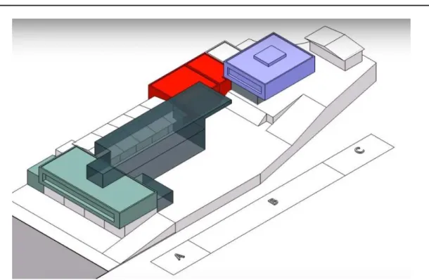
Figure 2 Conceptual model of the project
The architectural project, the basis for the required engineering studies, contemplates the intervention in existing structure and the expansion in the new part by requirements of the Scouts Association of Ecuador according to the following areas:
10
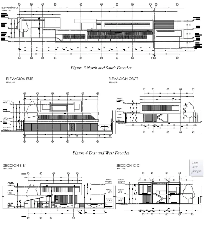
Figure 3 North and South Facades
Figure 4 East and West Facades
Figure 5 Sections B-B' and C-C'
Block A, opposite Av. America, includes commercial premises and offices, followed by block B, which includes the auditorium, offices, cafeteria and scout shop. Block C comprises residence, offices and storage. The quantity, dimensions and location of sanitary batteries, circulations, accesses, parking lots and other architectural components respond to the municipal requirements according to current regulations.
Main duties:
11 Defined the architectural characteristics of the project and the materials and construction systems to be used, the general planning of the structural systems of the building will be carried out. At the preliminary project level, seismic-resistant structural elements will be defined, columns, beams, slabs, walls, ramps, roofs, stairs, shear walls and foundations are pre-dimensioned. In order to get to the final dimensioning of the building structure, a process of optimization of its technical characteristics was followed, in order to define the structure that has the best economic conditions and the most suitable constructive characteristics, in such a way that they allow the execution of the project in the shortest possible time, at the lowest cost and in the best technical and safety conditions.
• Structural analysis
Defined the geometric characteristics of the structure, the mathematical models of structural type were elaborated, to perform the static and dynamic evaluation of the behavior of all the structural systems of the buildings, under the action of the permanent and occasional loads that will act on the building during its useful life. For its analysis, the structure of the building was considered spatially and the evaluation of its behavior was carried out through the use of computational software. All the frames were analyzed in two orthogonal directions, taking into consideration the action of the vertical, horizontal loads and the effects of torsion in the plant.
• Loads that will be used in the structural analysis
In the structural analysis of the building, two types of loads will be considered: permanent loads and occasional loads.
The permanent loads that will be considered are those produced by: the weight of the structure, the weight of the non-structural elements and the soil pressures.
The occasional loads that were considered are: the overload or live load that gravitates on the structure when it is in operation, the loads that will be generated during the construction process, the effects produced by the action of the earthquakes or by the action of the wind, any of the two load states that is most critical to the structure of the building. There were also taken into consideration, when the situation justifies it, the effects that are introduced into the structure due to temperature changes and because of the shrinkage produced during the concrete setting process. Within the occasional loads the one of greater importance and importance, by its magnitude and special characteristics of dynamic action on the structure, is the one produced by the seismic effects.
12
• Earthquake-resistant analysis
Due to the geotectonic characteristics and high seismicity in which the project is located, special attention was put to the analysis and design of the structure of the buildings to resist medium and high intensity earthquakes. For this purpose, the natural frequencies of the structure were determined, using dynamic analysis methods, the design spectra were defined for the seismic analysis and the responses of the structural systems to the most probable seismic actions were calculated.
• Structural Design: dimensioning and definitive design of structural elements
With the results obtained in the structural analysis processes for each one of the different permanent and occasional load states, according to the design codes used and for each of the cross sections of the structural elements of the building, the more critical combinations of the different effects: axial load, bending moment and cut, were used in the designs. With the knowledge of these maximum actions for each of the structural elements, I performed dimensioning and final design. This design includes: foundations, columns, diaphragms, walls, beams, slabs, ramps, deck, stairs, expansion joints and other minor structural parts. The designs were made in those materials that constitute the best technical, economic and constructive solution for the project.
• Drawing of structural drawings
The drawing of the structural plans was done on a computer using Autodesk AutoCAD Software. The structural plans include all the construction details, the technical specifications for the construction of the structure, slab casting areas, iron sheets for each of the structural elements, number of lightening, metal profiles, details of joints.
• Structural work volumes
For each of the structural elements of the buildings (foundations, walls, columns, slabs, beams, roof) were calculated the quantities of materials that are required for its construction: iron, concrete, lightening, metal profiles, etc.
The summaries with the quantities of materials were be included in each of the structural plans and were also be presented in an independent document as part of the final report.
13 The analysis and structural design were carried out in accordance with the current regulations of the "Ecuadorian Construction Standard" (NEC). All the analysis and design were carried out within the best and most updated engineering practices. The following design codes and standards will also be used as reference: for designs in reinforced concrete and prestressed concrete those established by the "American Concrete Institute" (ACI 318-99); and for the "Pre-stress Concrete Institute", PCI, for designs in steel those established by the "American Institute of Steel Construction" (AISC-99), the American Iron and Steel Institute (AISI) and the American Welding Society (AWS). ); for wood design those established in the "Wood Construction Primer" (PAD- REFORT / JUNAC); for general building design those established in the "Uniform Building Code" (UBC) and for the definition of the quality of the materials used in the construction established by the "American Society of Testing and Materials" (ASTM).
2.3
Two-stories residential house
The project includes a two-story single-family building with an area of 115.17 m2 for the1st floor and 110.14 m2 for the second floor in the city of Quito with a total construction area of 225.31 m2. The structural type of a building - reinforced concrete frame with columns of size 30x30 cm, beams - 20x30 cm, slab - 20 cm.
14
3
Masonry construction
In the field of Civil Engineering, the system of load-bearing walls has been widely used for many years in Ecuador. This type of construction has great qualities of acoustic and thermal insulation and has addressed the problems of affordable housing.
However, if these types of buildings do not have a proper reinforcement, they are vulnerable to natural agents such as wind that is very little or not taken into account in the design of these buildings. The wind factor was not taken into account for the structural calculation because the regulations did not ask for it, but in the NEC 2011(NEC-SE-CG, 2011) regulation it is essential to take this factor into account. A construction material, is any product processed or manufactured to be incorporated permanently in any work, whether building or civil engineering. In general, construction materials must meet these requirements:
Mechanical resistances according to the use they will receive. Chemical stability (resistance to aggressive agents)
Physical stability (dimensional). Security for its management and use.
Protection of the hygiene and health of workers and users. Do not conspire against the environment.
Thermal and acoustic insulation (collaborate in saving energy). Stability and protection in case of fire (resistance to fire).
Convenience of use, aesthetics and economy (NEC-SE-MP, 2015)
This type of traditional construction without reinforcement has a very low response to earthquakes causing several damages throughout its structure and in many cases causing significant structural problems since the reinforcement of the walls cannot be placed inside the bricks. In recent years, other types of problems have been observed more frequently, such as: cracks in the masonry caused not only by telluric movements but also by differential settlements, considerable deflections on the structure, and many other problems that arise during and after the construction process, which brings with it additional costs for its repair and loss of the functionality of the structure.
15
3.1
Types and construction processes
NON-REINFORCED MASONRY
It is the construction based on pieces of masonry joined by means of mortar that does not meet the minimum amounts of reinforcement established for the partially reinforced masonry. This structural system is classified, for effects of earthquake-resistant design, as one of the systems with minimum energy dissipation capacity in the inelastic range.
SIMPLE MASONRY
It is the type of structural masonry without reinforcement formed by pieces of masonry joined by means of mortar and that do not meet the minimum amounts of reinforcement established for partially reinforced masonry. The dominant efforts are compression which must counteract the stresses produced by the horizontal forces (NEC-SE-MP, 2015). However, this type of masonry lacks external and internal reinforcement and it is only the masonry that absorbs the requested efforts.
CONFINED MASONRY
Widely used in our environment, this type of confined masonry is reinforced throughout its perimeter by reinforced concrete elements, ie beams and columns, which will absorb the tractions produced by the lateral loads in the wall planes (NEC-SE-MP, 2015). In this type of masonry, the wall is first raised and then the confining elements, columns, chains and beams are all made of reinforced concrete.
BEARING MASONRY
It is the type of masonry built with clay bricks or blocks of concrete and mortar paste, with a reinforcement of electro-welded mesh on the faces of the wall, which is not composed of columns or beams in its perimeter, so the masonry forms the entire superstructure and is responsible for the transmission of the loads to the substructure (NEC-SE-MP, 2015).
REINFORCED MASONRY
It is brick masonry or reinforced concrete block by using steel rods distributed horizontally, vertically or both, embedded in mortar or concrete, forming a monolithic system, so that the system works together to withstand the stresses. The columns and beams will be reinforced concrete. This reinforcement will mainly resist tensile stresses
16 and occasionally when the masonry is not able to withstand compression and cutting forces this reinforcement will be able to absorb these stresses (NEC-SE-MP, 2015).
3.2
Elements that make up the masonry
BRICK
The brick is a piece in the shape of rectangular parallelepiped, clay or clay earth properly fired, in order to give it hardness. It can also be called brick as that unit whose size and weight allows it to be manipulated with one hand, the brick that will be used will be of the handcrafted type made of clay. In the case of the concrete block, a module unit of 20 cm in thickness x 20 cm in height and 40 cm in length is usually used (NEC-SE-Vivienda, 2015).
Compressive strength
The compressive strength of the bricks, f'm, shows a fairly wide range of variation, depending on the material and the type of unit. Table below shows the variation intervals of the compressive strength of various materials. All these values have been obtained by tests in isolated units, however, these values can suffer a drastic decrease when they are tested as part of a masonry panel. This effect is illustrated in Figure 7.
Table 2 Compression resistance of different masonry units
Material Compression resistance Stone 400 ... 1000 Concrete solid 150 … 250
Clay 50 … 200
Light concrete 40 … 140 Adobe 10 … 15
17
Figure 7 Stress-strain relationships for mortar, separated units and masonry panels
(Pauley et al., 1992)
There is not a very broad knowledge about the stress-strain relationship of the masonry units under compression. The results of experiments in clay bricks indicate that this relationship is almost linear until failure, at which point a rapid decrease in resistance follows.
The effect of perforations on compressive strength has been studied by several researchers. From experimental tests on perforated masonry units, it has been proved that this class of units, usually exhibit a very fragile behavior and the failure happens unexpectedly. Therefore, the use of perforated masonry units is not recommended for structures subjected to seismic actions. However, the Ecuadorian standard gives the following minimum values of compressive strength for the masonry units:
Table 3 Minimum compression resistance by NEC
(NEC-SE-Vivienda, 2015)
Unit type Compression resistance f'cu (MPa)
Solid brick 2
Clay brick with horizontal perforation 3 Concrete or clay block with vertical perforation 3
Modulus of elasticity and Poisson's ratio
The deformation stress ratio of the masonry units depends significantly on the constituent material. Due to the absence of experimental information, it can be assumed that the baked clay bricks behave almost like a linear elastic material, while the concrete units exhibit a non-linear behavior similar to that observed in the concrete plates.
18 The modulus of elasticity of the masonry units, Eb, presents a wide range of variation and, basically, depends on the type of material and the compressive strength. There is no standard method to evaluate the modulus of elasticity. Usually, this is taken as the secant modulus of elasticity, from zero stress level to one third of the strength of the material (Gutiérrez, 2004).
Moisture content and absorption
The moisture content and absorption are the most important properties of the units and have a considerable effect about the characteristics of the masonry.
The moisture content is defined as the mass of water per unit volume, which can be expressed, in absolute terms or in relative terms to the density of the unit when it is dry. The typical range of this parameter is 50-60 kg/m3 and 2-3% respectively(Gutiérrez, 2004).
MORTAR
It is known as a mortar to the grayish solid substance that is obtained from the mixture of a binder material, such as Portland cement. It is a filling material, made up of fine aggregates and water, which then hardens on contact with air.
Given their properties such as plasticity, consistency and being able to retain the minimum water for the hydration of the cement and, in addition, guarantee their adherence with the masonry units to develop their cementing action, they depend mainly on the quality of the materials used in their processing, and of course the dosage used, mortars have a wide variety of applications, such as the sticking of pieces of masonry or the coating of the same, better known in our environment as plaster.
The mortar paste should have good plasticity, consistency and be able to retain the minimum water for the hydration of the cement and also ensure its adherence with the masonry units to develop its action (NEC-SE-MP, 2015). The mortar used for the bonding of the masonry units has a volumetric dosage of 1: 3. The thickness of this mortar is 1.5cm, it is necessary to verify its uniform placement both horizontally and vertically on the masonry units.
The mortar used for the plaster of both masonries also has a volumetric dosage of 1: 3 and a thickness of 3cm measured from the masonry plane.
19 As well as the integrity of the masonry units, it depends on the manufacturer, in the case of the mortar, both the manufacturing process and placement (tasks performed by the mason) are finally those that define its quality.
CONCRETE
It is known as concrete to the homogeneous mixture produced between portland cement, fine aggregate, coarse aggregate and water. In our environment, concrete is the main material within the structural elements and like the mortar paste it hardens on contact with air.
In the case of reinforced or confined masonry the concrete of the confinement elements shall have a compressive strength greater than or equal to 210 kg / cm² or 21 MPa measured at 28 days and shall comply with the requirements established in the code (NEC-SE-MP, 2015), which are the existing standards and requirements for this type of structure. In my case I will use a concrete of 210 kg / cm² for the beams, columns and the slab.
3.3
Origin of the problems in the masonry
3.3.1
Seismic
Earthquake is called vibration or wave movement of the soil that occurs mainly by the release of energy, which accumulate in the earth due to strong stresses or pressures that occur in the interior. It is said that a building is a strong earthquake when it is designed with a suitable structural configuration, with components of appropriate dimensions and materials with a sufficient proportion and resistance to withstand the action of the forces caused by earthquakes (NEC-SE-DS, 2015).
3.3.2
Horizontal seismic forces
The system of horizontal forces equivalent to the seismic action that is applied according to the direction of analysis considered, is established by determining, first the value of the resulting horizontal seismic force or shear stress, from which the component forces of the system which in turn are assumed concentrated at the level of the mezzanines and roof of the construction, in which the gravitational loads have been concentrated.
20 The resultant of the horizontal forces equivalent to the seismic action or shear stress according to the direction of analysis considered, will be determined by the following expression:
= ∙ (1) Where:
- it is the resultant of the equivalent horizontal forces or cutting effort;
C - is the seismic coefficient of design, determined according to the seismic zone in analysis;
W - the total gravitational load on the base level of the construction.
The seismic coefficient of design C will be determined as established in the Ecuadorian code and depending on the seismic zone.
3.3.3
Interaction between the seismic forces and the
masonry
It is important to take into account that during the occurrence of an earthquake, the masonry due to its great rigidity are the first elements that will suffer the consequence of said earthquake. The most important property of bearing masonry in seismic zones is its response to dynamic actions once the inelastic range is abandoned. The behavior of the masonry due to multiple stresses to which it is exposed, is variable.
It must be taken into account that the masonry is not only subject to lateral seismic loads, but also to axial or vertical loads due to the weight of the live load and the dead load, in addition there may be possible wind, water or earth loads. Because of the type of stress to which this subjected the masonry, it presents different types of behavior and therefore different types of failure, among the most important are (NEC-SE-MP, 2015):
Shear failure
There are two types: failure by shear, when the crack is diagonal to 45º and runs only through the mortar joints, and fails by diagonal tension, when the crack is almost straight, breaking the pieces. The majority of these failures are due to the fact that the design in the structure is not taken care of by performing a proper test of the materials.
21
Figure 8 Failure due to shear
(Gutiérrez, 2004)
Diagonal tension failure
It is produced directly on the masonry units for values of moderate normal compression stresses. The shear strength of the mortar joints increases due to the effect of normal compression forces. Therefore, cracks occur in the units, as a result of tensile stresses induced by the state of compression and shear stresses. Figure 9 shows the distribution of the cracks that follow the direction of the vertical joints and pass through the units with an inclination that depends on the orientation of the main stresses in the unit.
Figure 9 Cracking of masonry units produced by diagonal tension failure
(Gutiérrez, 2004)
Failure due to axial load
This type of failure depends on the interaction between the masonry units and the glue mortar, since the units restrict the transverse deformations of the mortar, inducing compressive forces in the transverse plane and, in turn, generating tensile stresses on the units. masonry decreasing its resistance.
It is unusual for this type of failure to occur, and may be caused by poor quality parts or because they have lost load capacity due to weathering; and they are identified by vertical cracks in the middle or at the ends of the masonry.
22
Figure 10 Failure due to excessive vertical cracking caused by compression forces
(Gutiérrez, 2004)
Failure modes due to direct tension
Different types of failure can occur according to: 1) the direction of the tensile load and 2) the relative magnitude of the bond strength and the tensile strength of the masonry units.
When the tensile stresses are parallel to the horizontal mortar joints, two types of cracking can occur: a) completely vertical cracks that pass through the units (see Figure 11 a), where the resistance is controlled by the tensile strength of the masonry units and, b) cracks that do not affect the units and only occur along the mortar joints (see Figure 11 b), where the most determining factors are the shear strength and the overlap length (part of one brick covered by another, L0).
On the other hand, when the tensile forces act perpendicular to the horizontal mortar joints, failure modes usually occur by separation of the mortar-unit interfaces (see Figure 11 c). However, it can also occur tensile failure of the units, as shown in Figure 11 d.
23
Figure 11 Failure modes of masonry subject to direct tension
(Gutiérrez, 2004)
Failure due to flexion.
This type of failure is mainly due to the fact that the masonry lacks reinforcing steel since it absorbs stresses. It is identified by horizontal cracks in the ends of the walls that are very easy to observe.
3.3.4
Faults in the calculation of the masonry
structures
Below are some cases in which calculations fail in the masonry.
Soft Floor
This case occurs when the masonry is not continuous along the floors, generating greater rigidity in the upper floors and causing in the structure the effect of an inverted pendulum. This can be understood when in several floors, the ground floor lacks a sufficient number of walls, while in the upper floors the walls abound, in this case the problem of the flexible low floor and rigid upper floors has been generated, which in the presence of an earthquake efforts are concentrated in this soft floor.
24 This case is presented by pretending that the masonry alone absorbs the stresses of compression and tension. It is important that the reinforcement of masonry comply with the minimum reinforcement regulations. (NEC-SE-MP, 2015).
Short walls
This case occurs when the masonry is incomplete in height, generating the problem of the short walls, which likewise presents planes of failure in elevation of the structure, because it stiffens these short elements remarkably and causes the collapse. When it is the case in which a panel does not contribute positively to the structure or building, it should be thought of eliminating it, replacing it with some other solution or simply isolating it from the rest of the structure by means of a construction board.
Torsion
This phenomenon occurs when the floor of the building does not have uniformity or symmetry, in length and height in its configuration, which is known as irregularity in the floor, which generates an eccentricity between the center of mass and the center of rigidities, causing a moment due to the acting forces of the earthquake. Torque also occurs when there is a large concentration of masses, causing large rigidities in certain sectors of the structure. If the design and calculation of a structure does not comply with the requirements of geometry, this structure is considered vulnerable to the occurrence of an earthquake (NEC-SE-DS, 2015).
3.3.5
Differential settlements
This problem is mainly due to the poor quality of the soil on which the structure has been cemented, that is to say to have very soft soils, causing settlements, subsidence, cracks, and damage to non-structural elements and the weakening of the structure. The subsidence occurs due to the humidity of the land; on the other hand, the settlements are due to the weight of the structure.
3.3.6
Bad quality of materials
All the materials used in the construction of the masonry must be submitted to quality and resistance tests. A structure will be less vulnerable when the masonry units are of good quality and uniform, that is to say they do not present important cracks, they are not damaged or broken pieces. The masonry should be perfectly locked in all directions,
25 maintaining uniformity in all rows. The glue joints should be uniform and continuous, covering the masonry unit completely both horizontally and vertically, guaranteeing adherence in all units.
3.3.7
Behavior of load bearing masonry buildings
Because the structural response of masonry buildings varies according to the region of each country, these elements are susceptible to damage by earthquakes, so you can determine the typical efforts of: compression, flexo-compression, and shear. In the case of my project we are in zone V according to the seismic design map provided by the NEC-2011 ((NEC-SE-DS, 2015) that is of high seismic hazard and the value of its factor Z = 0.40, later we will use it for the calculations with the ETABS program.
3.3.8
Compression forces
In general, it can be said that the resistance to compression forces is acceptable for this type of structure, so, the resistance to axial loads is given mainly by the elements that make up the masonry, that is, the units of bricks, the mortar of glues and plaster. It must be taken into account that the two materials have different behaviors in terms of deformability, the brick is less deformable than the mortar, restricting the transverse deformations of the mortar despite being subjected to the same stresses.
3.3.9
Shear
The main fault element produced by these efforts is the appearance of cracks which cross the masonry, which present great weakness when subjected to earthquake or wind loads. This type of faults is manifested with a crack at 45 degrees, the same as can be seen in both directions, being able to observe an "X" known as the "X" of the earthquake.
26
4
Confined masonry
Confined masonry construction consists of masonry walls and horizontal and vertical reinforced concrete (RC) confining elements built on all four sides of a masonry wall panel. Vertical elements, called tie-columns, resemble columns in RC frame construction except that they tend to be of far smaller cross-sectional dimensions. Most importantly, these RC members are built after the masonry wall has been completed. Horizontal elements, called tie-beams, resemble beams in RC frame construction but they are not intended to function as conventional beams since confined masonry walls are load-bearing. Alternative terms, horizontal ties and vertical ties, are sometimes used instead of tie-beams and tie-columns. The key features of structural components of a confined masonry building are discussed below:
• Masonry walls transmit the gravity load from the slab(s) above down to the foundation (along with the RC tie-columns). This document addresses confined masonry construction consisting of masonry walls made of solid clay bricks, hollow clay tiles, or concrete blocks. The walls act as bracing panels, which resist horizontal earthquake forces acting in-plane. The walls must be confined by RC tie-beams and tie-columns and should not be penetrated by significant openings to ensure satisfactory earthquake performance.
• Confining elements (RC tie-columns and RC tie-beams) are effective in improving stability and integrity of masonry walls for in-plane and out-of-plane earthquake effects. These elements prevent brittle seismic response of masonry walls and protect them from complete disintegration even in major earthquakes. Confining elements, particularly tie-columns, contribute to the overall building stability for gravity loads.
• Floor and roof slabs transmit both gravity and lateral loads to the walls. In an earthquake, floor and roof slabs behave like horizontal beams and are called diaphragms. The roof slabs are typically made of reinforced concrete, but light-weight roofs made of timber or light gage steel are also used.
• Plinth band transmits the load from the walls down to the foundation. It also protects the ground floor walls from excessive settlement in soft soil conditions and the moisture penetration into the building.
27
4.1
Confined Masonry and Similar Building
Technologies
Confined masonry building technology is somewhat similar to both reinforced masonry and reinforced concrete frame construction with infill walls. It should be noted, however, that differences between these building technologies are significant in terms of construction sequence, complexity, and seismic performance.
For example, the main difference in the seismic behavior of the confined masonry (CM) and reinforced concrete frame buildings is that tie columns in confined masonry buildings cannot provide effective frame action due to it slenderness and not very high stiffness comparing to the masonry wall, because the size of the columns is relatively small. Also masonry wall in CM structure usually is integrated to the wall by the toothed surface of the wall and reinforcing bars. Moreover, in CM structures the masonry wall also supports gravity loads as well as tie columns.
When subjected to lateral seismic loads, walls in confined masonry buildings act as shear walls, similar to unreinforced or reinforced masonry walls or RC shear walls. On the other hand, infill wall panels in RC frame buildings do not act as shear walls - they act as diagonal struts.
Figure 12 A comparison of RC frames with masonry infills (a), and confined masonry construction (b)
(Meli, 2011)
4.2
Seismic behavior of confined masonry
structure
Seismic behavior of a confined masonry wall panel can be explained by composite (monolithic) action of a masonry wall and adjacent RC confining elements. This composite
28 action exists due to the toothing between the walls and the tie-columns - that is one of the key features of confined masonry construction. In the absence of toothing, composite action can be achieved by means of horizontal reinforcement (dowels).
A confined masonry wall panel can be modeled using the "strut and tie" model, where a vertical crack (separation) develops between the wall and the adjoining tie-columns. At the certain load level, the wall will start to act like a diagonal strut, while the adjacent columns act in tension and/or compression, depending on the direction of lateral earthquake forces.
Shear capacity of a confined masonry wall panel can be determined as the sum of contributions of the masonry wall and the adjacent RC tie-columns. The shear capacity of tie-columns can be reached only after the masonry has been severely cracked and its shear capacity has significantly decreased. As a result, it is recommended to consider only a partial contribution of tie-columns to the shear capacity of a confined masonry panel. A conservative estimate can be made by assuming that the tie-columns are integrated with the masonry wall, thus a cross-sectional area of the confined masonry wall can be calculated by taking into account the total panel length. This approach is the basis for deriving the minimum required wall density (Meli, 2011).
It can be seen from the diagram in Figure 13 that the stiffness and strength of a confined masonry panel drop following the onset of diagonal cracking in the wall (point 1). However, the load-resisting capacity of the panel is maintained until the critical regions of the confining elements experience significant cracking (point 2). This shows that a significant lateral deformation and ductility can be attained before the failure of a properly designed and constructed confined masonry panel (point 3).
29
Figure 13 Mechanism of shear resistance for a confined masonry wall panel: 1) diagonal cracking in the masonry wall; 2) diagonal cracks have propagated from the wall into the tie-columns, and 3) shear
failure of the RC tie-columns and the confined masonry wall panel (Meli, 2011)
Critical regions in a confined masonry structure are end zones of tie-columns (top and bottom region at each floor level), as shown in Figure 14.
In most cases, confined masonry panels demonstrate a shear-dominant seismic response. Longitudinal reinforcement in the RC tie-columns provides an adequate flexural resistance, thus the flexural failure mechanism does not govern.
Figure 14 Critical regions in a confined masonry building: a general diagram showing critical regions in the RC tie-columns
(Meli, 2011)
Confined masonry panels are subjected to the effects of axial gravity load (due to self-weight and tributary floor/roof loads). Figure 15a illustrates a confined masonry panel which resists the combined effect of axial load P and bending moment M. The capacity of the composite confined masonry panel section under the combined effect of axial load and