An integrated framework to support remote IEEE 1149.1 /
1149.4 design for test experiments
José M. M. Ferreira1, António M. Cardoso2, Manuel G. O. Gericota3 1,2
University of Porto (FEUP / DEEC), 3 Polytechnic Institute of Porto (ISEP / DEE)
Keywords: Design for test, mixed-signal testing, remote / web-based
experimentation, IEEE 1149.1 / 1149.4 test standards.
Abstract
Remote experiments for academic purposes can only achieve their educational goals if an appropriate framework is able to provide a basic set of features, namely remote laboratory management, collaborative learning tools and content management and delivery. This paper presents a framework developed to support remote experiments in a design for test class offered to final year students at the Electrical and Computer Engineering degree at the University of Porto. The proposed solution combines a test language command interpreter and various virtual instruments (VIs), with a demonstration board that comprises a boundary-scan IEEE 1149.1 / 1149.4 test infrastructure. The experiments are presented as embedded learning objects, with no distinction from other e-learning contents (e.g. lessons, lecture notes, etc.).
1 Introduction
E-learning platforms are now widely used in many academic domains, providing a relevant added value in terms of pedagogical effectiveness. However, e-learning platforms traditionally fall behind teachers’ expectations, when it comes to support access to laboratory experiments. This situation is not serious when simulation packages are an alternative to achieve the same educational goals, but such a replacement is not always possible. Particularly in the case of multidisciplinary experiments using easily available devices, it may be simpler and cheaper to set up a remote experimentation workbench [1,2]. Even in the case of non-multidisciplinary areas that use easily available devices, there are pedagogic arguments for preferring remote experiments to simulation packages, since the awareness of reality increases motivation. Whatever the case, it is important to embed the remote experiments into the learning platform, instead of isolating them from the accompanying e-learning materials.
Pedagogic issues related to remote experimentation (or indeed experimentation in general) are not however restricted to their integration into the e-learning platform [3,4]. Laboratory experiments are traditionally carried out in the form of group work, and as such any remote experimentation setup must provide adequate tools to enable synchronous communication among the students (that may participate in the experiment from various locations).
The learning effectiveness of remote experimentation is compromised if one or more of these features is not present. It is worth looking into the general requirements that must be taken into consideration when preparing a remote experiment, and to proceed from there to more domain-specific requirements for a given experiment. This paper starts by presenting the selected experimentation domain and then relates it to the corresponding experiment / workbench requirements. The specific experiments that are currently proposed to the design for test students at FEUP are then described. The research topics that are currently under consideration are presented, and a concluding section closes the paper.
2 IEEE 1149.1 / 1149.4 experiments
The experiments that are presented ahead address the test of mixed-signal circuits that are compliant with the IEEE 1149.4 standard [5]. Any integrated circuits that are compliant with this test standard have a dedicated test cell associated to every functional pin, which connects the pin to the core when the circuit is in mission mode (normal circuit operation), or isolates the pin from the core when in test mode. IEEE 1149.4 is an extension of IEEE 1149.1 [6], which defines a similar test architecture that is nowadays present in most digital VLSI circuits.
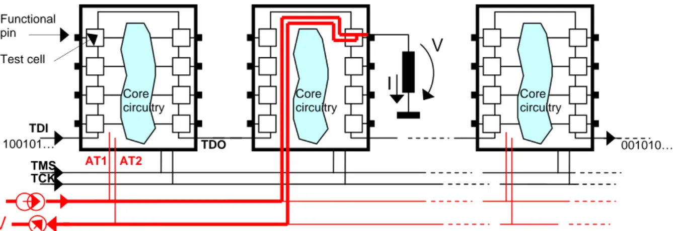
The test cells present at digital pins are known as digital boundary modules (DBM), and those present at analog pins are know as analog boundary modules (ABM). DBMs and ABMs are serially connected to form the boundary-scan register (BSR), as illustrated in figure 1. The overall on-chip test architecture comprises the BSR and various other data and control registers that are required to support structural and parametric test operations. Interface to this on-chip test architecture is done via a digital 4-pin test access port (TAP): TDI (test data in), TDO (test data out), TMS (test mode select) and TCK (test clock). A 2-pin analog test access port (ATAP) is present in all IEEE 1149.4-compliant circuits to handle analog signals. One of the ATAP pins (AT1) is used to drive an analog test stimulus and the other one (AT2) is used to observe the corresponding analog test response. The operating mode of DBMs and ABMs is defined by a sequence of control and data bistreams that are shifted into the TDI-TDO path. These bitstreams are at the heart of the IEEE 1149.X test protocol and their specification is made in the form of a test program specified in SVF [7], which is the outcome of the work proposed to the students.
Figure 1: Test cells (DBMs / ABMs) and boundary-scan register in an 1149.4 chip.
IEEE 1149.X embedded test architectures have a cost (they degrade performance, increase pin count and silicon area), but their availability greatly simplifies production test. The expression design for test indicates that the embedded test circuitry is brought into the design at a very early stage in the development process, with the main objective of facilitating all subsequent test operations.
3 Experiment / workbench requirements
Design for test courses that include 1149.4 mixed-signal test experiments require a workbench comprising at least an oscilloscope, a waveform generator, and a multimeter (current and voltage measurement). These instruments will suffice to handle the necessary
I V 100101… 001010… I V TDI TMS TCK TDO AT1 AT2 Functional pin Test cell Core circuitry Core circuitry Core circuitry
operating mode of the embedded test architecture, some form of digital test controller is also necessary. Finally, any real experiment will need a demonstration board where one or more IEEE 1149.X circuits are present.
Additional requirements will have to be considered if all or part of the students are able to carry out their experiments from a remote location (instead of being all present in the lab). A synchronous communication tool is required to enable on-line discussions as the experiment progresses. Video-conferencing is of course the preferred solution, since the information transfer rate of text-based chat is not satisfactory in this context.
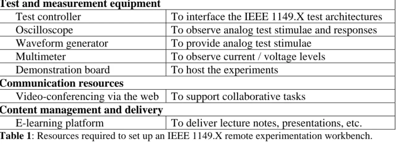
Finally, remote experimentation in an academic context hardly makes any sense when the accompanying learning contents and materials are not provided electronically. Any remote experimentation setup must therefore envisage its integration into an e-learning platform that will be used to deliver lecture notes, presentations, assessment exercises, etc. The requirements identified to setup an IEEE 1149.X design for test remote experimentation workbench may therefore be summarised as shown in table 1.
Test and measurement equipment
Test controller To interface the IEEE 1149.X test architectures
Oscilloscope To observe analog test stimulae and responses
Waveform generator To provide analog test stimulae
Multimeter To observe current / voltage levels
Demonstration board To host the experiments
Communication resources
Video-conferencing via the web To support collaborative tasks
Content management and delivery
E-learning platform To deliver lecture notes, presentations, etc.
Table 1: Resources required to set up an IEEE 1149.X remote experimentation workbench.
In the case of remote experiments, all test and measurement equipment will of course possess an appropriate web interface, usually known as a Virtual Instrument (VI). For most cases this is not a problem, since various instrument manufacturers also provide software packages to enable web observation and control. LabView is a good example of a technology that supports local or remote interface panels for a wide range of instruments. In the case of experiment-specific resources, however, extra development work may be necessary to provide an appropriate user interface. That is the case with the 1149.1 dedicated test controller (from Göpel Electronic GmbH), since its user interface must enable the specification and execution of the required test programs. A dedicated LabView interface was therefore developed for this purpose.
4 Application examples
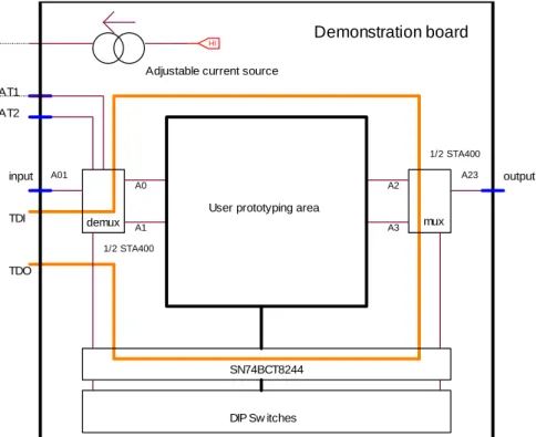
The demonstration board that was developed to support remote IEEE 1149.1 / 1149.4 experiments may be represented as shown in figure 2 (the DBMs / ABMs associated with digital and analog I/O pins are not represented for the sake of simplicity). The STA400 circuit comprises two 2:1 bidirectional mux/demux blocks which are used to route the analog signals between the input and output of the board. In addition to this IEEE 1149.4-compatible circuit, the board comprises an IEEE 1149.1 octal buffer, which together with the STA400 defines the board test infrastructure (the control and data bitstreams traverses the board-level TDI-TDO path). A built-in adjustable current source provides an analog test stimulus that may be used to drive AT1 when performing parametric tests (e.g. when measuring the value of one resistor placed in the user prototyping area).
input output demux mux SN74BCT8244 DIP Sw itches 1/2 STA400 1/2 STA400 A0 A2 A1 A23 A01 A3 Demonstration board AT2 AT1 TDO TDI
Adjustable current source
HI
User prototyping area
Figure 2: Demonstration board used to support remote IEEE 1149.4 mixed-signal test experiments.
4.1 Experiment description: Observability
This experiment is proposed with the objective of demonstrating that the IEEE 1149.4 test architecture supports a non-intrusive operating mode to enable the observation of the analog signal at any pin that has an ABM (using the 1149.4 PROBE instruction). The switching structures in the 1149.4 test architecture route the selected (input or output) pin to AT2, without disturbing the operation of the circuit. An oscilloscope connected to AT2 displays the waveform present at the selected pin.
input demux SN74BCT8244 A1 A0 1/2 STA400 Demonstration board A01 AT2 AT1 TDI
Adjustable current source
TDO
HI
User prototyping area Oscilloscope
Waveform generator
In one specific experiment proposed to the students, a waveform generator drives the STA400 A01 pin, which may be connected to A0 or to A1, depending on the control input of this demux block. As represented in figure 3, the objective of this experiment consists of connecting A1 to AT2, and then verifying that the control input of the multiplexer is able to divert the input waveform from A0 to A1 and vice-versa.
The work proposed to the students consists of writing the test program that will set up the appropriate operating mode in the IEEE 1149.X test architecture of both chips (the STA400 and the SN71BCT8244). In this experiment the analog chip will be in mission mode (operating normally), while the octal buffer will be placed in “external test” (EXTEST) mode. Since the outputs of the second chip are now controlled via its IEEE 1149.1 boundary-scan test cells, it is possible to control the STA400 multiplexer via the TDI-TDO test data path. Besides writing the test program, the students need to adjust the waveform generator and the oscilloscope, and to register all observations that may be included in the experiment report. Their tasks may be summarised as follows:
1. Define a test strategy (i.e. what specific test actions will enable them to achieve the experiment objectives)
2. Find out the TDI-TDO bitstreams that set up the appropriate operating mode for the IEEE 1149.X test architecture present in the STA400 and BCT8244 chips
3. Write the corresponding test program, execute it and observe the test results
Notice that communication is important for all the tasks referred above. The test program will be written by one of the students, who will be in control of the experiment interface (the student that requested and was granted control of all VIs). The remaining students are able to observe what is going on, since all VIs are seen simultaneously by all participants.
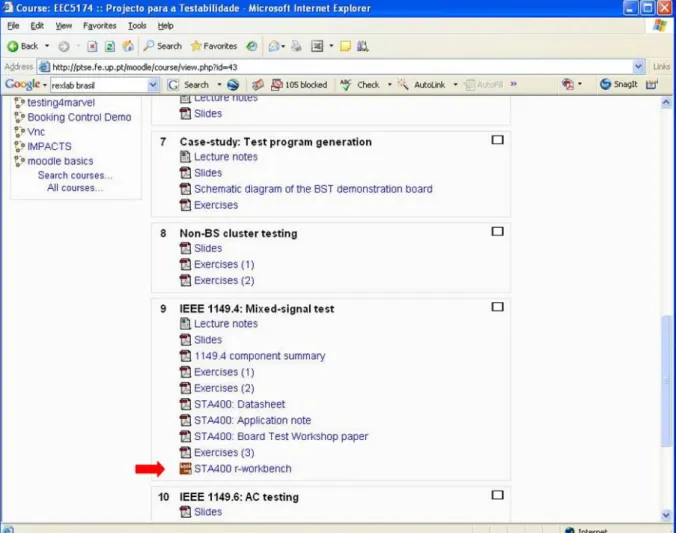
Access to the remote workbench must be reserved beforehand. A booking tool was therefore developed as an extension of Moodle, the open-source e-learning platform that was selected to support this framework [8]. This tool may indeed be used to share any scarce resources in a co-ordinated manner (e.g. to share a general purpose video-conferencing room). The link to the SVF interpreter experiment – which is actually the link to the booking tool – is illustrated in figure 4 and is seen by the students just as any other activities created by the teachers. Clicking to book access time will open a weekly agenda, where the students may select one or more one-hour slots (the maximum number of slots for each team may be predefined by the teacher for each experiment). When the current time is within the selected time slot(s), a link to launch the experiment will be automatically generated (the reserved time slot may again be released if the students that made the reservation do not access the experiment within a predefined time delay).
The experiment interface is divided across two browser windows that are launched sequentially when one of the students starts the experiment. The interface elements comprised in these two windows are the following:
Window #1
Test controller To interface the digital 4-pin 1149.1 TAP
Video-conferencing via the web To support collaborative tasks
Window #2
Oscilloscope To observe analog test stimulae and responses
Waveform generator To provide analog test stimulae
Multimeter To observe current / voltage levels
Live images from the lab To reinforce awareness of reality
Figure 4: Link to the experiment in the Moodle contents.
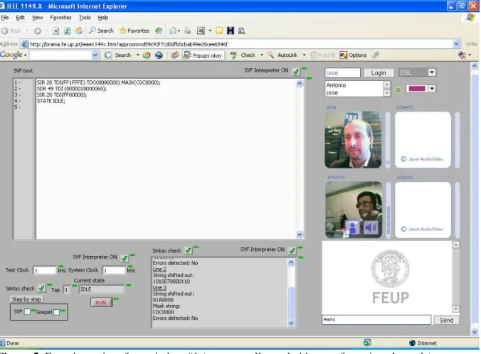
Test program specification and execution, and test result analysis, are the tasks where discussion is more important. As such, the test controller interface panel was merged with the video-conferencing channels in a single browser window, shown in figure 5. Recall that only one student will be able to write the test program, but all the remaining students are able to see it in real time and to contribute as needed. Once the test program is written, execution will follow. The log area below the test program specification window provides runtime information as each test command is executed. The students conclude the experiment by recording all relevant data and submitting a report for assessment.
All test and measurement VIs, as well as live images from the lab, are present in the second browser window, shown in figure 6. The multimeter is not necessary for this experiment and the corresponding VI might have been removed when the teacher created the experiment. However, their presence ensures that the students will become acquainted with a standard experimentation environment and as such there are no reasons to remove it (it would not necessarily be removed from a standard workbench set up in a real lab, just because it was not going to be used in a given experiment).
Figure 5: Experiment interface window #1 (test controller and video-conferencing channels).
Figure 6: Experiment interface window #2: Oscilloscope, waveform generator, multimeter, live images from the remote lab. Notice that the multimeter is not used in this case and that the live images from the remote lab reinforce the perception of a real experiment.
4.2 Experiment description: Controllability
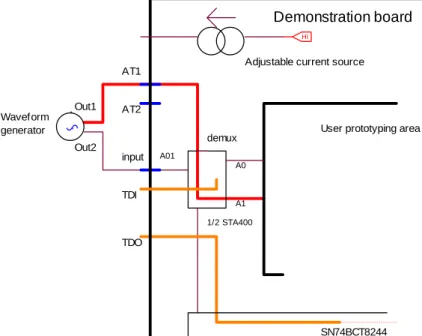
This experiment is represented in figure 7 and illustrates the intrusive EXTEST mode (normal circuit operation will be suspended while in this mode). When the IEEE 1149.X test architecture is configured to operate in EXTEST, all core circuitry is isolated from the pins. Structural and parametric test operations may be carried out while in EXTEST mode. Structural tests will drive the PCB interconnects to HIGH or LOW voltage levels, with the objective of detecting open or short-circuits. It is also possible to use the ATAP pins to route an analog stimulus to any analog pin for parametric test purposes.
The objective of one specific experiment proposed to the students consists of controlling the A1 output of the STA400 demux block. An external test signal present at AT1 (which is driven by a waveform generator) will be routed to A1. Since A1 is now controlled from AT1, regardless of the operating mode of the internal demux block, this experiment requires the core circuitry to be isolated from the pins. The experiment interface windows are again as represented in figures 5 and 6 (notice that the multimeter is once again not necessary).
Out1 Out2 demux input 1/2 STA400 SN74BCT8244 A1 A0 Demonstration board A01 AT2 AT1 TDI
Adjustable current source
TDO
HI
User prototyping area Waveform
generator
Figure 7: Test set up for the controllability experiment (intrusive).
4.3 Experiment description: parametric testing
In this experiment the students are asked to determine the value of one resistor placed between an STA400 pin and ground. The test setup is represented in figure 8 and shows that the resistor is placed between pin A0 and GND.
The switching structures in the 1149.4 test architecture will i) disconnect A0 from the core circuitry (all other pins will also be disconnected from the core circuitry, since this is an intrusive operation); ii) connect A0 to both pins in the ATAP (AT1 and AT2). The current driven through AT1 will flow out of A0 and via the unknown resistor R to ground. The value of the current driven into AT1 is measured in the external ampmeter. Since AT2 is also connected to A0, the voltage drop across R will be measured in the external voltmeter. The value of the unknown resistor will be calculated as R = V / I (error considerations are omitted from this description for the sake of simplicity).
input demux R = ? Unknown v alue SN74BCT8244 1/2 STA400 A0 A1 A01 Demonstration board AT2 AT1 TDI
Adjustable current source
TDO
HI
User prototyping area Am pm eter
Voltm eter
Figure 8: Test setup for a parametric testing experiment (intrusive).
The required configuration of the 1149.4 switching structures will determine the necessary TDI-TDO bitstreams and therefore the new test program. If runtime errors are not detected (syntax errors or errors found in the bitstreams shifted out), the students will conclude the experiment by reading the resistor value (the ampmeter and voltmeter readings are available, but the multimeter VI also provides the result of the calculation). The experiment interface elements in the second browser window are shown in figure 9 and are the same as before, but the multimeter is the only test and measurement equipment needed.
Figure 9: Experiment interface window #2 for parametric testing: Oscilloscope, waveform generator, multimeter, live images from the remote lab. Notice that the oscilloscope and the waveform generator are not used in this experiment.
5 Future research
Various remote experiments in similar areas were previously setup and made available to students before the 1149.1 / 1149.4 design for test framework herein described. Seen from the students’ point of view, all remote experimentation requirements have been met, and virtual / mixed-mode / remote experiments may now be integrated into most e-learning platforms. However, when seen from the teachers’ point of view, the situation is less satisfactory. There are at least two areas where further research and development is still required:
- Internet programming skills should not be required to set up web-based experiments, since the teachers’ expertise will only occasionally reside in this area. The automatic generation of experiment interfaces, built from a library comprising various interface elements (e.g. oscilloscope, waveform generator, video-conferencing channels, live images from the lab, etc.), is therefore important to support teachers who might otherwise never come to use this technology.
- Formative assessment is usually done by the teacher when he accompanies the work done by his/her students in a real lab. In that context the teacher will circulate among the students and note down positive or negative impressions that result from the actions observed in each student group. This information is of course important and appropriate means should be made available to capture and store it when the experiment is carried out via the web. The interface elements referred in the previous paragraph should therefore include embedded assessment features, able to detect when the students exhibit higher or lower than average skills in each context (e.g. if the student needs to adjust the time base, but repeatedly modifies the V/div control instead of the time/div control, such action should be registered and made available to the student and teacher at the end of the session).
Teacher support is therefore an area where further investment is still needed in order to promote the acceptance and pedagogic effectiveness of web-based experiments.
6 Conclusion
The integrated framework described in this paper addresses design for test of mixed-signal circuits and brings together several modules that were developed in previous projects. The general resources provided comprise synchronous communication by video-conferencing (to support collaborative tasks), a booking tool (to enable co-ordinated resource sharing in the remote workbench and to facilitate the organisation of student activities), and a panoply of standard workbench instruments, e.g. oscilloscope, waveform generator and ampmeter / voltmeter functions. Experiment-specific resources comprise a dedicated experiment board that is based on the first commercial chip supporting the IEEE 1149.4 embedded test standard (the STA400 IC from National Semiconductor), and an SVF test command interpreter that interfaces an IEEE 1149.1 TAP controller board from Göpel Electronic GmbH. Since this SVF interpreter was written in LabView, it offers the same “look-and-feel” of the remaining VIs that are present in this remote workbench.
The booking tool provides a bridge to the e-learning platform used to deliver the course contents, and was developed in the form of a PHP extension to Moodle. This tool enables the teachers to include access to the experiment as a standard activity when building the course contents, and enables the remote experiments to be perceived by the students just as any other embedded learning object. The current setup is being used in a design for test course that is lectured to final year students in the Electrical and Computer Engineering degree at the University of Porto (FEUP).
For usability reasons, the experiment interface uses two browser windows. A two-window interface requires frequent swap operations, but we concluded that swapping is less disturbing than regular up/down scrolling.
The readers (and everyone interested in web-based experimentation) should be aware that such tools are not to be offered as a replacement to real laboratories, but rather as a complement to real lab sessions. Virtual / mixed-mode / remote experimentation extends e-learning to the lab, but does not eliminate the importance of the student-teacher interaction, and student access to real labs. Moreover, in the near future we will see enhanced web-based experimentation interfaces that generate client profiles and formative assessment information. The interface to an oscilloscope may continue to look like the “real thing”, but there is no reason to prevent it from being able to provide a much richer learning experience (in the same way that e-books may go far beyond the reading experience of printed books).
Acknowledgments
This work is supported by an FCT program under contract POSC/EEA-ESE/55680/2004.
References:
[1] Gustavsson, Ingvar, Zackrisson, Johan, Åkesson, Henrik, Håkansson, Lars, Claesson, Ingvar, and Lagö, Thomas. "Remote Operation and Control of Traditional Laboratory Equipment." International Journal of Online Engineering (iJOE) [Online], 2.1 4 Feb 2006 Available:
http://www.i-joe.org/ojs/viewarticle.php?id=43.
[2] Ferreira, José, Muller, Dieter, “The MARVEL EU project: A social constructivist approach to remote experimentation”, Remote Engineering and Virtual Experimentation Symposium (REV 2004), Villach (Austria), September 2004.
[3] Grigoriadou, M.; Kanidis, E.; Gogoulou, A., “A Web-Based Educational Environment for Teaching the Computer Cache Memory”, IEEE Transactions on Education, Vol. 49, Issue 1, February 2006, pp. 147- 156.
[4] Ko, C.C., Chen, Ben M., Chen, Jianping, Creating Web-based Laboratories (Advanced Information and Knowledge Processing), Springer, ISBN 1852338377, 2004.
[5] IEEE 1149.4 Standard for a Mixed Signal Test Bus, IEEE Computer Society (Test Technology Standards Committee), 28 March 2000.
[6] IEEE 1149.1-2001 (Revision of IEEE Std 1149.1-1990) Standard Test Access Port and Boundary-Scan Architecture, IEEE Computer Society (Test Technology Standards Committee), 25 October 2001.
[7] Serial Vector Format (SVF) [Online], http://www.asset-intertech.com/support/svf.html (visited on April 18th 2006).
[8] Ferreira, José, Cardoso, António, “A Moodle extension to book online labs”, Remote Engineering and Virtual Experimentation Symposium (REV 2005), Brasov (Romania), June 2005.
Authors
:
Jose M. M. Ferreira, Associate Professor
University of Porto (FEUP), Department of Electrical and Computer Engineering Rua Roberto Frias, 4200-465 Porto - PORTUGAL
António M. Cardoso, Eng.
University of Porto (FEUP), Department of Electrical and Computer Engineering Rua Roberto Frias - 4200-465 Porto - PORTUGAL
Manuel Gradim O. Gericota, Assistant Professor
Polytechnic Institute of Porto (ISEP), Department of Electrical Engineering Rua Dr. António Bernardino de Almeida, 431 - 4200-072 Porto – PORTUGAL [email protected]