Graduated in Physics and Chemistry Teaching
Characterization of Molecular Damage
Induced by UV Photons and Carbon Ions
on Biomimetic Heterostructures
Dissertation to obtain the PhD Degree in Physics
Speciality Condensed Matter Physics
Supervisor: Maria de Fátima Guerreiro da Silva Campos Raposo,
Assistant Professor, Universidade Nova de Lisboa
Co-supervisor: Paulo António Martins Ferreira Ribeiro,
Assistant Professor, Universidade Nova de Lisboa
Jury:
President: Prof. Doutor António M. D. de Sá Nunes dos Santos Examiners: Prof. Doutora Ana Margarida M. V. de Barros Timmons
Doutora Octávia Gabriela da S. V. Nené Monteiro Gil Vowels: Prof. Doutora Maria Luísa Dias de Carvalho S. Leonardo
Prof. Doutor Henrique Leonel Gomes
Prof. Doutor Paulo Manuel Assis Loureiro Limão Vieira Prof. Doutora Amélia Maria P. S. Gonçalves da Silva Prof. Doutora Maria de Fátima G. S. Campos Raposo
III
© Paulo Jorge Pereira Gomes; FCT/UNL; UNL
Characterization of Particle Effects in Biomolecular Heterostructures
V
To My Mother, Júlia
VII
A
CKNOWLEDGEMENTS
Prof. Dr. Maria Raposo for the first insights into condensed matter physics during my undergraduate years and for her commitment in supporting me throughout the years developing the PhD work. My eternal gratitude for the opportunities created since the time of graduation, when I was invited to join the research group, up to today, having always placed enormous confidence in me as an individual, and in my scientific and pedagogical capabilities, allowing my development over the years. Thanks Maria by your friendship.
Prof. Dr. Paulo Ribeiro for the guidance given throughout this work, for is support during the hard weeks working in external institutions and is willingness and camaraderie, important for good moments of relaxation.
Prof. Dr. Amélia Gonçalves da Silva for accepting to join the committee for monitoring this PhD thesis, for giving me the opportunity to have access the laboratory over her direction, for the support and accompaniment provided, and transmitted by learning which greatly contributed to my development in achieving scientific and pedagogical maturity.
Prof. Dr. Maria de Lourdes Costa for inviting me during graduation to develop research in her laboratory. Without this opportunity, certainly, I would not delve into the area of scientific research.
Prof. Dr. Nigel J. Mason from the Centre of Molecular and Optical Sciences, The Open University, UK, for financial and institutional conditions created, that enabled the development of a large part of the work of this PhD.
Doctor Søren Vrønning Hoffmann and Doctor Nykola Jones from Institute for Storage Ring Facilities, University of Aarhus, Denmark, for their supervision, discussion and assistance while working on the synchrotron radiation facility.
Prof. Dr. Robert Mc. Cullough from Center of Plasma Physics, School of Mathematics and Physics, Queen’s University of Belfast, for their supervision, discussion and assistance while
working on the ion beam facility.
Prof. Dr. Madalena Dionísio from Chemistry Department, Universidade nova de Lisboa, for her supervision, discussion and assistance while working on the impedance spectroscopy facility.
Prof. Dr. Ana Botelho do Rego from Centro de Química Física Molecular, Instituto Superior Técnico, Universidade de Lisboa, for their collaboration and discussion with the measurements done on the x-ray photoelectron spectroscopy facility.
Doctor David Shaw from Daresbury Laboratory, Daresbury Science & Innovation Campus, UK, for their supervision, discussion and assistance while working on the synchrotron radiation facility.
Prof. Dr. Paulo Limão-Vieira by the opportunities to visit and meet other international research groups and to participate in several international projects.
VIII
Dr. Andreia Duarte, Mestre Margarida Coelho, Mestre Gonçalo Martins e Mestre Luís Abegão for their great friendship, and discussions and collaboration in the development of the work over several stages of this PhD.
Doctor João Lourenço, Doctor Carla Madruga, Doctor Quirina Ferreira, Eng. Jorge Ribeiro and remaining elements that went through the Grupo de Sistemas Moleculares Funcionais, for the opportunities over the years, the support provided and developed.
Prof. Dr. Osvaldo Novaes Jr., Doctor Marli Moraes and other elements of the Grupo de Física de Polímeros do Instituto de Física São Carlos, for collaborating on several projects developed.
Mrs. Helena Rodrigues for their support since the time of graduation, for her friendship and encouragement in the most troubled times of my career in the Physics Department of Universidade Nova de Lisboa.
The Department of Physics and CeFiTec Staff for technical and bureaucratic support throughout these years.
Dr. Ana Ramos by upholding me in the final phase of this work and for their important contribution to their conclusion.
Dr. Glória Pires for early learning with physical and chemical, through its teachings, and its assertive words in my vocational guidance, which led me to reach this ambitious academic goal.
My friends Ana Duarte, Célia Pereira, Daniel Duarte and Miguel Cunha for the relentless friendship, encouragement and unconditional support in all these years, in most important and memorable moments.
My friends Filipe Romão and José Carlos Martins for their encouragement and support on thesis graphic edition.
My aunt Helena by awakening the dazzle for knowledge and learning who developed the strength to achieve ambitious goals.
My parents Júlia and José. Thanks for the education and knowledge they transmitted to me through all these years that made me who I am and that greatly contributed to the achievement of these professional goals. To you father, that are no longer among us, special thanks for having been present and for everything you did so I could reach this goal. To you mother, thank you for being always present in my life and for your support at all times…
All other collaborators, friends and familiars not referenced who have contributed directly or indirectly, positively or negatively for the developed of these works, thanks for your contribution.
IX
A
BSTRACT
The study of the effect of radiation on living tissues is a rather complex task to address mainly because they are made of a set of complex functional biological structures and interfaces. Particularly if one is looking for where damage is taking place in a first stage and what are the underlying reaction mechanisms. In this work a new approach is addressed to study the effect of radiation by making use of well identified molecular hetero-structures samples which mimic the biological environment. These were obtained by assembling onto a solid support deoxyribonucleic acid (DNA) and phospholipids together with a soft water-containing polyelectrolyte precursor in layered structures and by producing lipid layers at liquid/air interface with DNA as subphase. The effects of both ultraviolet (UV) radiation and carbon ions beams were systematically investigated in these heterostructures, namely damage on DNA by means vacuum ultraviolet (VUV), infrared (IR), X-Ray Photoelectron (XPS) and impedance spectroscopy. Experimental results revealed that UV affects furanose, PO2-, thymines, cytosines and adenines groups. The XPS spectrometry carried out on the samples allowed validate the VUV and IR results and to conclude that ionized phosphate groups, surrounded by the sodium counterions, congregate hydration water molecules which play a role of UV protection. The ac electrical conductivity measurements revealed that the DNA electrical conduction is arising from DNA chain electron hopping between base-pairs and phosphate groups, with the hopping distance equal to the distance between DNA base-pairs and is strongly dependent on UV radiation exposure, due loss of phosphate groups. Characterization of DNA samples exposed to a 4 keV C3+ ions beam revealed also carbon-oxygen bonds break, phosphate groups damage and formation of new species. Results from radiation induced damage carried out on biomimetic heterostructures having different compositions revealed that damage is dependent on sample composition, with respect to functional targeted groups and extent of damage. Conversely, LbL films of 1,2-dipalmitoyl-sn-Glycero-3-[Phospho-rac-(1-glycerol)] (Sodium Salt) (DPPG) liposomes, alternated with poly(allylamine hydrochloride) (PAH) revealed to be unaffected, even by prolonged UV irradiation exposure, in the absence of water molecules. However, DPPG molecules were damaged by the UV radiation in presence of water with cleavage of C-O, C=O and –PO2- bonds. Finally, the study of DNA interaction with the ionic lipids at liquid/air interfaces revealed that electrical charge of the lipid influences the interaction of phospholipid with DNA. In the presence of DNA in the subphase, the effects from UV irrladiation were seen to be smaller, which means that ionic products from biomolecules degradation stabilize the intact DPPG molecules. This mechanism may explain why UV irradiation does not cause immediate cell collapse, thus providing time for the cellular machinery to repair elements damaged by UV.
XI
R
ESUMO
O estudo do efeito da radiação em tecidos vivos constitui uma tarefa complexa uma vez que estes são constituídos por um conjunto de estruturas biológicas com interfaces e funções específicas e complexas. A complexidade aumenta quando se pretende estudar onde ocorre o dano numa primeira fase e os posteriores mecanismos de proliferação dos danos. Neste trabalho é utilizada uma nova abordagem para o estudo do efeito da radiação, recorrendo ao uso de heteroestruturas preparadas com moléculas bem identificadas que simulam o meio biológico. Neste trabalho foram desenvolvidas heteroestruturas em substrato sólido, compostas por diferentes combinações de ácido desoxirribonucleico (ADN), fosfolípidos e polieletrólitos que possibilitam a retenção das moléculas de água, e pela produção de camadas lipídicas na interface líquido/ar, com solução aquosa de ADN como subfase. Os danos por radiação
ultravioleta (UV) e feixe de iões carbono (C3+) foram caracterizados por espectroscopia de
ultravioleta de vácuo (VUV), de infravermelho (IV), de fotoeletrões de raio-X (XPS) e de impedância. Os resultados revelaram que a radiação UV danifica as moléculas de furanose,
timina, citosina, adenina e os grupos PO2-. Os resultados de XPS obtidos permitiram não só
validar os resultados já obtidos como também concluir que os grupos fosfato ionizados, rodeados por iões sódio, retêm água, protegendo-os da radiação UV. As medições de condutividade eléctrica do ADN revelaram que a condução processa-se por saltos de electrões entre os pares de base e os grupos de fosfato com a distância de salto igual à distância entre os pares de bases de ADN sendo, devido à perda de grupos fosfato, dependente da exposição
à radiação UV. A caracterização de amostras de ADN exposta a um feixe de iões de C3+
revelou também a quebra de ligações carbono-oxigénio, danos nos grupos fosfato e formação de novas espécies. Dos resultados obtidos foi possível concluir que os danos induzidos pela radiação nas heteroestruturas biomiméticas, cuja composição varia entre estudos, dependem da composição da amostra, afetando diferentes grupos moleculares e em diferentes extensões. Por outro lado, filmes LbL de 1,2-dipalmitoil-sn-glicero-3-[fosfo-rac(1-glicerol)] (sal de sódio) (DPPG) lipossomas, alternado com poli (cloridrato de alilamina) (PAH) revelaram-se inalterados, mesmo em caso de exposição prolongada a radiação UV na ausência de moléculas de água. No entanto, as moléculas de DPPG foram danificadas por radiação UV na
presença de água, com a quebra de ligações CO, C=O e -PO2-. Finalmente, o estudo da
interacção de ADN com lípidos iónicos nas interfaces líquido/ar revelou que a carga eléctrica do lípido influencia a sua interacção com o ADN. Na presença de ADN na subfase, os efeitos de radiação UV foram visivelmente menores, o que significa que os produtos iónicos de degradação das biomoléculas estabilizam as moléculas intactas de DPPG. Este mecanismo pode explicar por que a radiação UV não causa o colapso das células imediato, dando tempo para a célula ativar os mecanismos de reparação, corrigindo os danos causados pela radiação UV.
XIII
C
ONTENTS
Acknowledgements ... VII Abstract ... IX Resumo ... XI Contents ... XIII Figures ... XVII Tables ... XXIII Acronyms and Symbols ... XXV
1. Introduction ... 1
2. The effects of radiation on biological systems ... 5
2.1. Biological environment ... 5
2.1.1. The cell ... 5
2.1.2. Cell membrane ... 6
2.1.3. Phospholipids ... 6
2.1.4. Cell nucleus ... 9
2.1.5. Deoxyribonucleic Acid ... 10
2.2. Radiation – Matter Interaction ... 13
2.2.1. Radiation ... 13
2.2.2. Electromagnetic Radiation and Biological Systems ... 13
2.2.3. Biological effect of electromagnetic radiation ... 15
2.3. Cell Medium Mimetization ... 18
2.3.1. Bionic and Biomimetics ... 18
2.3.2. Origin and Evolution of a New Science ... 19
2.3.3. Biomimetics of membranes ... 19
2.4. Biosensors ... 21
2.4.1. Biosensors development ... 21
2.4.2. Electrical impedance biosensors ... 22
3. Experimental Methods ... 23
3.1. Thin films preparation techniques ... 23
3.1.1. Cast technique ... 23
XIV
3.1.3. Langmuir monolayers technique ... 25
3.1.4. Substrates ... 26
3.2. Particles sources ... 27
3.2.1. Photon sources ... 27
3.2.2. Ion sources ... 34
3.3. Characterization Techniques... 41
3.3.1. Ultra-vacuum ultraviolet absorption spectroscopy ... 41
3.3.2. Infrared Fourier Transform Spectroscopy ... 44
3.3.3. X-ray photoelectron spectroscopy ... 45
3.3.4. Atomic Force Microscopy ... 46
3.3.5. Langmuir Balance ... 48
3.3.6. Impedance Spectroscopy ... 51
4. Results ... 55
4.1. Biomimetic Heterostructures for Radiation Damage Studies ... 55
4.2. Photoabsorption of biomolecules and radiation damage – studies in adenine films ... 63
4.3. UV Degradation of deoxyribonucleic acid ... 71
4.4. XPS Analysis of damage caused by UV radiation on DNA: energy thresholds for breaking different DNA groups ... 89
4.5. DNA damage induced by carbons (C3+) beam accessed by independent component analysis of infrared spectra ... 101
4.6. Characterization of PAH/DPPG Layer-by-layer films by VUV spectroscopy ... 111
4.7. Interaction of DNA with Langmuir monolayers of opposite charged phospholipids ... 123
4.8. Radiation damage on Langmuir monolayers of the anionic 1,2-distearoyl-sn-glycero-3-phospho-(1'-rac-glycerol) (DPPG) phospholipid at the air-DNA solution interface ... 131
4.9. Probing radiation damage by AC conductivity as a method to characterize electron hopping in DNA molecules ... 139
5. Final Remarks ... 147
5.1. Conclusions ... 147
5.2. Future Work ... 150
5.3. Publications and Communications related to PhD Works ... 151
5.3.1. Papers in International Journals ... 151
XV
5.3.3. Invited Oral Communications ... 152
5.3.4. Oral Communications ... 152
5.3.5. Poster Communications ... 153
XVII
F
IGURES
Figure 2.1. Cell structure: (A) Prokaryotic cell; (B) Eukaryotic cell []. ... 5
Figure 2.2. Eukaryotic cell membrane structure – Fluid-mosaic model []. ... 6
Figure 2.3. Shematic summary of lipids classification... 7
Figure 2.4. Glycerophospholipids structure [16,17,18]. ... 8
Figure 2.5. Sphingolip structure [16,17,18]. ... 8
Figure 2.6. Examples of steroids: A) Cholesterol; B) 24-methylene-3β,4β,22 -trihydroxycholesterol. ... 9
Figure 2.7. Cell nucleus structure: 1 – Nuclear envelope, 2 – Ribosomes, 3 – Nuclear pores, 4 – Nucleolus, 5 – Chromatin, 6 – Nucleus, 7 – Endoplasmic reticulum, 8 – Nucleoplasm []. ... 9
Figure 2.8. Cell nucleus: composition and structural units [14,15,16, 19]. ... 10
Figure 2.9. DNA double helix. (A and C) Helical structure. (B) Molecular composition and complementary base-pairing [19]. ... 11
Figure 2.10. DNA double helix structure properties of A, B and Z forms []. ... 11
Table 2.3. DNA double helix structure characteristics of A, B and Z forms [31]. ... 12
Figure 2.11. Regions of the electromagnetic spectrum and respective sources []. ... 13
Figure 2.12. Example of the OH• radical representative reactions. (A) Pyrimidines; (B) Purines. ... 16
Figure 2.13. Example of the H• radical representative reactions in nitrogenous bases. ... 16
Figure 2.14. Example of reactions occurring in the presence of oxygen. ... 17
Figure 2.15. Types of damage produced by ionizing radiation in the DNA molecule. ... 17
Fig. 2.16. Schematic representation of lipid bilayer and SUV, LUV, MLV and MMV. ... 20
Figure 3.1. Scheme illustrating the film preparation using the spilling technique. ... 23
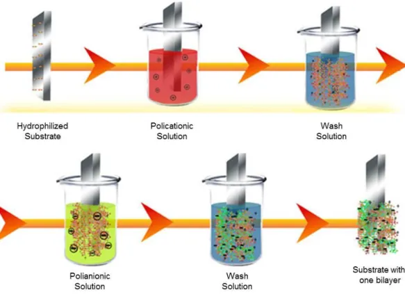
Figure 3.2. Scheme illustrating the layer-by-layer preparation method of a bilayer film. ... 24
Figure 3.3. Scheme illustrating the preparation method of a Langmuir layer. ... 25
Figure 3.4. Spectral power emission relative distribution curve of UVC lamps. Adapted from [71]. ... 27
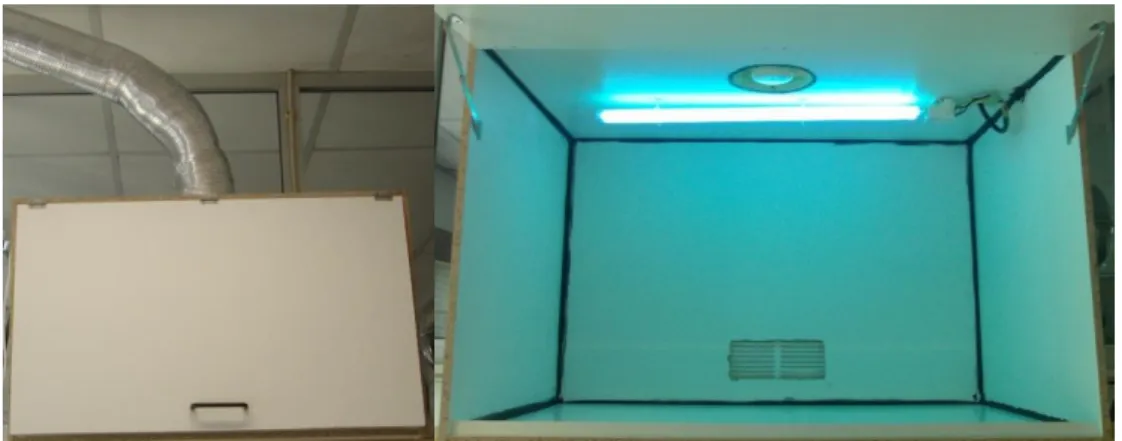
Figure 3.5. Extraction chamber developed to irradiate the samples with a 254 nm low pressure mercury lamp. ... 28
Figure 3.6. Simplified scheme of a synchrotron accelerator. Adapted from [82]. ... 29
Figure 3.7. Schematic representation of the synchrotron accelerator magnetic components: A – dipole magnet; B – Wiggler. Adapted from [82]. ... 29
Figure 3.8. Schematic representation of the disposition of the various SRS components and their respective workstations. Adapted from [79]. ... 30 Figure 3.9. Schematic representation of the assembly used in obtaining an absorption spectra of vacuum UV synchrotron radiation: 1 – manual drawer valve with CaF2 window, 2 – four way crosshead, 3 – piranni type pressure sensor, 4 – flexible membrane, 5 – metallic valve with a manual drawer, 6 – six valve crosshead, 7 – three way valve, 8 – turbomolecular pump, 9 –
XVIII
measurement control unit with a digital indicator, 13 – manual escape valve. Adapted from [80]. ... 31 Figure 3.10. Normalized decay curve for the beam current during a 24 hour period after injection. Bold line corresponds to an extended exponential adjustment. Adapted from from de [80]. ... 32 Figure 3.11. Schematic representation of the ASTRID synchrotron accelerator. Adapted from []. ... 33 Figure 3.12. Minimum B-field configuration. Adapted from [83]. ... 35 Figure 3.14. Schematic of the 10 GHz ECR ion source and extraction system. Adapted from [83]. ... 37
Figure 3.15. Schematic diagram of the “floating beamline” accelerator. Adapted from [83]. ... 39 Figure 3.16. Schematic diagram irradiation and FTIR measurements setup. Adapted from [83]. ... 40 Figure 3.17. Schematic representation of the energy levels. Adapted from [85]. ... 41 Figure 3.18. Schematic representation of the energy levels. Adapted from [86]. ... 42 Figure 3.19. VUV absorbance spectrum of a DNA cast film, obtained in the region between 130 and 300 nm. ... 43 Figure 3.20. Stretching vibration modes: (A) asymmetrical and (B) symmetrical. ... 44 Figure 3.21. Schematic representation of the four modes of deformation vibrations. ... 44 Figure 3.22. FTIR absorbance spectrum of a DNA cast film within 875 to 4000 cm-1 region. .... 45 Figure 3.23. Schematic representation of the XPS apparatus. Adapted from []. ... 46 Figure 3.24. Schematic representation of the atomic force microscope (AFM) apparatus. The tip is fixed under a crossbeam where the light beam hits and consequently it is reflected, and whose purpose is detecting the crossbeam movement with a four-quadrant photodetector. Adapted from [97]. ... 47 Figure 3.25. Schematic representation showing the existing forces between tip and surface plotted against relative distance. ... 48 Figure 3.26. Langmuir trough used in Langmuir monolayer preparation: (a) KSV 2000; (b) KSV 5000. ... 49 Figure 3.27. Scheme illustrating Wilhelmy method. (a) Experimental system; (b) Representation of the variables needed to determine the surface tension, [22]. ... 49 Figure 3.28. -A isothermal curve displaying its distinct phases (variations may occur according to the system composition and the working temperature) and illustration of the molecules special disposition. ... 50 Figure 3.29. Graphical representation of complex impedance in the complex plane. Im –
Imaginary component axis, Re – Real component axis, Z – Impedance, R – Resistance, jX –
XIX
Figure 4.1.2. Plot of the ratio between the percentage of oxygen atoms which are not related with the assembled polyelectrolytes and the percentage of ionic groups associated to them. The POMA/PSS films were prepared from PSS aqueous solutions with the ionic strength of sodium chloride (NaCl) and potassium chloride (KCl). ... 59 Figure 4.1.3. Normalized infrared peak area at 1090 cm-1 relative to peak area at 961 cm-1 of a DNA cast sample and PAH/DNA film irradiated for different periods of time with synchrotron radiation at 140 nm. The lines are imposed exponential decays. ... 60 Figure 4.2.1. Schematic sequence of layer-by-layer (LBL) technique for membranes’ production.
... 66 Figure 4.2.2. VUV absorbance spectra of a cast adenine film after and before irradiation at 140 nm with an estimated UV dose of about 8.5 × 10⁻⁴ W/m2. ... 66 Figure 4.2.3. Absorbance at a fixed wavelength as a function of the number of bilayers for LbL films of adenine/PVS at pH=3. ... 68 Figure 4.3.1. The vacuum ultraviolet absorbance spectrum of a DNA cast sample. The solid lines correspond to spectrum peak structure obtained by fitting of VUV spectrum with a set of Gaussians. ... 73 Figure 4.3.2. Absorbance spectra of a DNA cast sample for different irradiation time periods using 140 nm wavelength radiation. ... 74 Figure 4.3.3. DNA VUV spectra, after correction for baselines, for different irradiation times in the 170 to 230 nm range. ... 75 Figure 4.3.4. Peak area versus the irradiation time for a DNA cast film. Peak centered at: a) 162 nm; b) 188 nm and 202 nm and c) 263 nm. ... 76 Figure 4.3.5. Infrared absorbance spectra of a DNA cast sample before and after irradiation with 140 nm UV light for 80 minutes. ... 77 Figure 4.3.6. Ratios of the infrared peak areas at 1020 cm-1 (furanose vibrations), 1061 cm-1 (CO stretch of the furanose in backbone) and 1097 cm-1 (symmetric PO2- stretching of backbone) relative to the peak area of the 961 cm-1 feature. The peak area was calculated from infrared peaks obtained from spectra of DNA cast sample irradiated for different periods of time using 140 nm synchrotron radiation. The solid lines are guidelines. ... 80 Figure 4.3.7. Normalized infrared peak area ratios at 1061 cm-1(CO stretch of the furanose in backbone), 1097 cm-1 (symmetric PO
XX
Figure 4.3.9. Normalized infrared peak area ratios at 1366 cm-1 (cytidine and guanosine in anticonformation) and 1390 cm-1 (CH3 Symmetric deformation of deoxyribose thymine) relative to peak area at 961 cm-1 of a DNA cast sample irradiated for different periods of time with synchrotron radiation at 140 nm. The solid lines are guidelines. ... 82 Figure 4.3.10. Normalized infrared peak area ratios at 1280 cm-1 (C5=C6 vibration of cytidine and CN3H bend of deoxyribose thymine), 1414 cm-1 (C3’-endo deoxyribose in A-form helices and C3’-endo deoxyribose in Z form helices) and 1446 cm-1 (adenine A, B and Z forms) relative to peak area at 961 cm-1 of a DNA cast sample irradiated for different periods of time with synchrotron radiation at 140 nm. The solid lines are guidelines. ... 83 Figure 4.3.11. Normalized infrared peak area ratios at 1280 cm-1(C5=C6 vibration of cytidine and CN3H bend of deoxyribose thymine), 1390 cm-1 (CH3 Symmetric deformation of deoxyribose thymine) and 1701 cm-1 (C2=O2 strength of thymine single stranded or double stranded and C6=O6 stretching of guanines involved in Hoogsteen third strand binding and/or C2=O2 stretching of thymines involved in reverse Hoogsteen third strand binding) relative to peak area at 961 cm-1 of a DNA cast sample irradiated for different periods of time with synchrotron radiation at 140 nm. The solid lines are guidelines. ... 84 Figure 4.3.12. Normalized infrared peak area ratios at 1693 cm-1 (C2=O2 strength of thymine single stranded or double stranded), 1711 cm-1 (C6=O6 stretching of guanines involved in Hoogsteen third strand binding and/or C2=O2 stretching of thymines involved in reverse Hoogsteen third strand binding) and 1701 cm-1 (C2=O2 strength of thymine single stranded or double stranded and C6=O6 stretching of guanines involved in Hoogsteen third strand binding and/or C2=O2 stretching of thymines involved in reverse Hoogsteen third strand binding) relative to peak area at 961 cm-1 of a DNA cast sample irradiated for different periods of time with synchrotron radiation at 140 nm. The solid lines are guidelines... 85 Figure 4.3.13. Normalized infrared peak area ratios at 1210 cm-1 (antisymmetric PO
XXI
XXII
XXIII
T
ABLES
Table 2.1. Example of glycerophospholipids composition [16,17,18]. ... 8 Table 2.2. Example sphingolip structure composition [16,17,18]. ... 8 Table 3.1. Table depicting the main features of each workstation used in the sample irradiation protocol. ... 33 Table 3.2. Table showing the respective electronic transitions for each region of the electromagnetic spectrum. Adapted from [85]. ... 42 Table 4.2.1. Adenine absorption features, assignments, peak areas and relative peak areas after and before irradiation. ... 67 Table 4.3.1. Characteristics of peaks observed in DNA cast films by VUV. ... 74 Table 4.3.2. Characteristic infrared absorptions in DNA cast films. The Peak Area Ratio Tendency (PART) indicates the increase or decrease with irradiation time of each peak area relatively to the 961 cm-1 peak area. [153,154] ... 78 Table 4.4.1.Element composition in percentage, obtained from XPS spectra taken at take-off angle of 0º relatively to normal surface of DNA cast films, irradiated with 1.14×10¹⁵ photons UV beam at different wavelengths. Relative errors are estimated to be less than 10% for components and less than 2% for the total. Sample not irradiated but submitted to ambient light conditions during handling was considered as irradiated at 340 nm. ... 93 Table 4.4.2. Summarization of the energy values of the different DNA groups damaged. ... 99 Table 4.5.1 Features of ICA Component 2 spectrum associated with DNA damage. ... 109 Table 4.6.1. Peak position and FWHM parameters for the peaks obtained from fitting the VUV spectra and corresponding assignments of DPPG and PAH cast films and PAH/DPPG LbL
XXV
A
CRONYMS AND
S
YMBOLS
A Absorbance
A Adenine
A Area
Abs Absorbance
AC Alternating Current AFM Atomic Force Microscopy
ASTRID Aarhus Storage Ring in Denmark a.u. Arbitrary Units
B Magnetic Field
BE Binding Energy
BE Bond Energy
B3LYP Becke, Three-parameter, Lee-Yang-Parr
C Cytosine
CAPES Fundação Coordenação de Aperfeiçoamento de Pessoal de Nível Superior CBH Correlated Barrier Hopping
CD1 Setup to Circular Dichroism and Photoabsorption Spectroscopy Studies CEMOS Centre of Molecular and Optical Sciences
CNPq Conselho Nacional de Desenvolvimento Científico e Tecnológico COST European Cooperation in Science and Technology
DF Departamento de Física DLS Dynamic Light Scattering
DLTGS Deuteriated L-Aniline Doped Triglycine Sulfate DNA Deoxyribonucleic Acid
DPPG 1,2-distearoyl-sn-glycero-3-phospho-(1'-rac-glycerol) DSB Double Strand Break
e Electron Charge
E Irradiance
EBIS Electron Beam Ion Sources EBIT Electron Beam Ion Traps
ECCL Electron Controlled Chemical Lithography ECR Electron Cyclotron Resonance
EDPPC 1,2-distearoyl-sn-glycero-3-ethylphosphocholine EIPAM Electron Induced Processing at the Molecular Level
EM Electromagnetic
ESI Electrospray Ion Sources ESF European Social Fund
EU European Union
XXVI
f Frequency
FAT Fixed Analyser Transmission
FAPESP Fundação de Amparo à Pesquisa do Estado de São Paulo FCT Faculdade de Ciências e Tecnologia
FCT Fundação para a Ciência e Tecnologia FTIR Fourier Transform Infrared Spectroscopy FWHM Full Width at Half-maximum
G Gaseous
G Guanine
GRICES Gabinete de Relações Internacionais da Ciência e do Ensino Superior
I Radiation Detected
I Current Intensity
ICA Independent Component Analysis I0 Incident Radiation
Im Imaginary Component
IR Infrared
ISA Institute for Storage Ring Facilities
J Current Density
jX Indutance
K Kelvin
k Boltzmann Constant
K Transition Energy Ks-1 Compressional Modulus
KE Kinetics Energy
l Length
LC Liquid Condensed
LE Liquid Expanded
LET Linear Energy Transfer
LB Langmuir-Blodgett
LbL Layer-by-Layer
LINAC Linear Particle Accelerator LUV Large Unilamelar Vesicles
m Mass
MCI Multiply Charged Ion
MEC Ministério do Ensino e Ciência MLV Multilamelar Vesicles
Mw Average Molecular Weight N Concentration of Pair Sites PAH Poly(allylamine hydrochloride
XXVII PEI Polyethylenimine
pH Hydrogen Potencial
PhD Doctor of Philosophy POMA Poly(o-methoxyaniline) PSS Poly(styrene sulfonate)
PVS Poly(vinylsulfonic acid Poly(o-methoxyaniline)sodium salt)
q Electric Charge
QMT Quantum Mechanical Tunnelling QUB Queen’s University of Belfast
r Radius
R Correlation Coefficient R Hopping Distance
R Resistance
RADAM Radiation Damage in Biomolecular Systems RNA Ribonucleic Acid
s Thickness
S Solid
SRS Daresbury Synchrotron Radiation Source SSB Single Strand Break
STM Scanning Tunneling Microscope SUV Small Unilamelar Visicules
T Temperature
T Thymine
UK United Kingdom
UNL Universidade Nova de Lisboa USA United States of America
UV Ultraviolet
UV1 Experimental Setup to Photoabsorption Spectroscopy Studies UVC Ultraviolet C
v Linear Velocity
V Voltage
VUV Vacuum Ultraviolet
WC Watson-Crick
WM Energy Barrier
XPS X-ray Photoelectron Spectroscopy
Z Atomic Number
Z Impedance
Zʹ Real Component of Impedance Zʹʹ Imaginary Component of Impedance
XXVIII
Exponential Coefficient
Surface Tension
Adsorbed Amount per Layer per Unit Area
Phase Angle
Partial Derivative
Δt Time Frame
Absorbance Coefficient
Dielectric Constant
0 Permittivity of Free Space
Surface Pressure
c Collapse Pressure
Complex Conductivity
Relaxation time
0 Characteristic Relaxation Time
1
1.
I
NTRODUCTION
The mutagenic or lethal effects of ionising radiation at the cellular level can be traced to structural and chemical modification of the biomolecular environment and its constituents. As far as radiation is concerned, not only is deoxyribonucleic acid (DNA) found to be a sensitive biomolecule in living tissue, but also the effects on the cellular constituents, namely the cell membrane, are not to be discarded particularly when its role on the interface mechanisms within the cell are vital for the physiological balance survival. Although the radiation damage in biological tissues has been extensively investigated, the processes that occur at molecular level are not well understood [1]. In fact, it is known that when ionizing radiation attains the matter, it produces in very short periods of time large amount of ions, radicals, excited neutrals and ballistic secondary electrons with initial kinetic energies below 100 eV [2,3], which causes physical and chemical modifications in the medium. Moreover, it was shown that electrons with energies between 4 to 6 eV induce strand break formation in double-stranded supercoiled DNA [3,4]. Concerning the effect of low energies, in the ultraviolet range, several efforts have been developed in order to attain answers about interaction mechanisms leading to damage at the molecular level. Results of radiation damage carried out in DNA plasmid investigated using 7-150 eV synchrotron radiation [5], revealed DNA single-strand (SSB) and double-strand (DSB) breaks occurs in all energy range, for both dry and solution plasmid DNA. The presence of water molecules was seen to boost the radiation effect [6], due to OH● radical and other reactive oxygen species, such as the superoxide radical and oxygen peroxide. It is now well established that low energy electrons (< 30 eV) on DNA/RNA and its constituents (the nucleotide bases, nucleosides and water) can increase the damage probability, at very specific incident energies or resonances [4,7]. Moreover, the effect of these low energy electrons through dissociative electron attachment processes have been found to be site and bond selective as a function of the energy [8].
2
better understand radiation damage in these biological molecules under conditions close to the cell environment, where water molecules are known to play a relevant role. Due to past experimental results within this thematic, this work started with the characterization of the effect of UV radiation on DNA cast films by means of by vacuum ultraviolet spectroscopy (VUV), Fourier transform infrared spectroscopy (FTIR) and X-ray photoelectrons spectroscopy (XPS). The obtained results with the nitrogenous bases showed that the damage depends on the nature of the heterostructure in the study, thus it was considered more appropriate to the study of the DNA molecule instead of their various elementary units. The studies performed show that although these may be visible changes in the VUV spectrum of films of DNA, they are not sufficient to characterize the changes at the molecular level, unlike infrared spectroscopy that has shown that most characteristic bands of chemical bonds decreased in intensity, and generally the affected bonds are the C-O stretch of the furanose in backbone, in the PO2- groups, in the thymines, cytosines and adenines groups. UV radiation was shown to affect the thymines involved in reverse Hoogsteen third strand binding which is consistent with the observed decrease C2=O2 stretching of thymines involved in reverse Hoogsteen third strand binding, while the C2=O2 stretching vibration of thymine in single or double-stranded remain unchanged. The XPS spectroscopy allowed validate the VUV and IR results and conclude that ionized phosphate groups, surrounded by the sodium counterions, congregate hydration water molecules which play UV radiation protection a role. At a later stage of this work came the opportunity of also conducting studies on damage caused by ion beams, namely carbon ions. Since the exposure of carbon ions beam is being currently addressed for cancer therapy, measurements on their effect on DNA samples have also been included in this thesis.
In real biological systems the DNA molecule is within the nucleus, which consists of a phospholipid membrane, thus it was considered important, after the study of radiation damage in the DNA chain, understand if the phospholipid membrane comprises a barrier protective radiation or present other behaviour. It was considered important to carry out studies on the effect of UV radiation on phospholipids but, due to the short and limit period of time to access to the synchrotron facilities, just one phospholipid was selected, DPPG, because is an constituent of lung, that is one of most affected tissues in the case of carcinogenic pathology. DPPG solution and DPPG cast films were prepared and to facilitate the DPPG adsorption on the substrate and to preserve the water molecules in the sample, DPPG/PAH layer-by-layer films were prepared. The samples were irradiated and studied by UV spectroscopy and atomic force microscopy, allowing the UV spectrum characterization and concluding that the LbL films were not affected by prolonged UV irradiation in the absence of water molecules indicating that the VUV technique can be used for characterization of lipid heterostructures.
3
with the study of the effect of radiation on DPPG monolayers, having concluded that at high surface pressures, corresponding to a real membrane, the DNA molecules decreased monolayer instability caused by irradiation.
Finally being the radiation necessary for the anticancer therapy emerged the idea to create a radiation biosensor that allows monitors the radiation exposure during the therapies. The electrical impedance sensors are the most adequate to this function, so DNA cast films electrical characterization was done by impedance spectroscopy. The obtained results reveals experimentally about the DNA electrical conduction mechanism was electron hopping between base-pairs and phosphate groups, where these work as electron acceptors. The hooping distance was calculated using the correlated barrier hopping (CBH) model and revealed to be equal to the distance between base pairs. The results obtained show that the electrical conductivity can be used to monitor DNA damage by UV radiation, condition important to the UV radiation biosensor. Moreover, it was found that the electrical conductivity is proportional to the number of phosphate groups in the DNA chain, and therefore, this conclusion allows explain the divergence found in the literature about its electrical properties where there is no agreement is DNA is conductor, semiconductor or insulator.
5
2.
T
HE EFFECTS OF RADIATION ON BIOLOGICAL SYSTEMS
The study of physical and chemical damage occurring in models of the cellular environment, termed biomimetic systems, was the purpose of the work presented in this dissertation. This chapter examines the theoretical concepts necessary to understand the experimental results, in particular the cell model, the interaction between radiation and the cellular environment, processes for mimicking cell and the use of these models in the development of biosensors for radiation.
2.1.
B
IOLOGICAL ENVIRONMENT2.1.1.
T
HE CELLThe cell is the basic unit of life. It is the structural and functional unit of all living beings. The cells were first observed in 1665 by Robert Hooke [13] when examining cork slides under a crude microscope. A cell theory was only developed in 1847 by Theodor Schwann and Matthias Jakob Schleiden stating that all organisms are composed of one or more cells. All cells come from preexisting cells. Vital functions of an organism occur within cells [14], and all cells contain the hereditary information necessary for regulating cell functions and for transmitting information to the next generation of cells [15]. There are two main groups of cells, prokaryotic and eukaryotic cells.
(i) Prokaryotic: These cells are usually small, lack a nucleus and do not have any membrane-bound organelles (see figure 2.1.A). The genetic information of prokaryotes is typically in nucleoid of DNA strands arranged in a circular shape, but they may have additional DNA in a circular loop called a plasmid [16,17,18].
(ii) Eukaryotic: These cells are more complex than prokaryotic cells. Its volume is about 10 times higher than the prokaryotic cells and may reach volumes 1000 times larger. The main differences are the existence of many types of organelles and a nuclear membrane which stores the DNA that offers a spiral configuration associated with proteins (see figure 2.1.B). The complex of DNA and proteins is called chromatin. The membrane that surrounds this type of cell contains the same functions as a prokaryotic cell membrane, varying slightly in the configuration. Unlike in animals, plants present cell waals which prevent the cellular expansion after absorbing water [16,17,18].
(A) (B)
6
2.1.2.
C
ELL MEMBRANEThe cell membrane, also known as plasmatic or cytoplasmic, represents one of the main components of the cell, since it defines the bounds and adjusts the transport mechanisms across cell waals. The membrane structure obeys the Fluid-Mosaic model, suggested by Seymour Jonathan Singer and Garth L. Nicolson in 1972, which states that the membrane is considered a two-dimensional liquid where molecules diffuse freely [20]. Despite this model being the one accepted by the scientific community, research is still ongoing. It is, however, well known that the fluidity of the membrane depends on the type of connection that occurs between the phospholipids. Connections only occur between phospholipids and proteins, without any covalent bonds, resulting from hydrophobic forces and hydrogen bonds [16,17,18]. The cell membrane is essentially formed by a phospholipid bilayer with integral (intrinsic) and peripheral (extrinsic) proteins, as depicted in figure 2.2. The cell membrane displays characteristics such as high hygroscopicity, selective permeability, a porous surface, a system for active transport of ions and numerous enzymes across the membrane which help its molecular stabilization. In addition, eukaryotic membranes have significant amounts of cholesterol that decreases membrane fluidity due to the presence of its rigid planar ring structure [16,17,18].
Figure 2.2. Eukaryotic cell membrane structure – Fluid-mosaic model [21].
2.1.3.
P
HOSPHOLIPIDS7 Figure 2.3. Shematic summary of lipids classification.
In the body these molecules are mediators of intra and intercellular signaling, they also constitute the main energy reserves (triacylglycerols) and lastly, they are the main structural elements of biological membranes. Although the relative amount of each type of lipid varies according to the organism the membranes hold [16,17,18]:
(i) Glycerophospholipids: They are the main constituents of biological membrane since they form the double lipid layer. They have a highly polar head group, integrated with a phosphate group, and a nonpolar aliphatic tail [16,17,18].
Lipid
s
Fatty Acids
Satured
Unsatured
Glycerolipids
Acylglycerol
Monoacylglycerol
Diacylglycerol
Triacylglycerol
Glycerophospholipids
Diacylglycerol-phospholipids
Phosphatic Acid
Phophatidylcholine
Phosphatidyethanol-amine
Phosphatidylserine
Phosphatidylinositol Plasmalogens
Plasmanogens Glucoglycerolipids
Sphingolipids
Ceramides
Glycerosphingolipids
Sphingophospholipids
8 Figure 2.4. Glycerophospholipids structure [16,17,18].
Table 2.1. Example of glycerophospholipids composition [16,17,18].
Glycerophospholipid designation
Substituent Group designation
Substituent Group structure
Phosphatidic acid Hydrogen -H
Phosphatidylethanolamine Ethanolamine -CH2-CH2-NH3+
Phosphatidylcholine Choline -CH2-CH2-N+-(CH3)3
Phosphatidylserine Serine -CH2-CH2-N+-(CH3)3
Phosphatidylglycerol Glycerol -CH2-CHOH-CH2OH
Phosphatidylinositol Inositol -CH(CHOH)5
(ii) Sphingolipids:Biological membrane’s second class of lipids which mostly derives of sphingosine
(C18) and has an amine chain link connecting the hydrophobic chain to the hydrophilic head [16,17,18].
Figure 2.5. Sphingolip structure [16,17,18].
Table 2.2. Example sphingolip structure composition [16,17,18].
Sphingolipid designation Substituent Group designation Substituent Group structure
Ceramide Hydrogen -H
Sphingomyelin Choline -CH2-CH2-N+-(CH3)3
Glycocerebroside Glucose -CH-(CHOH)4O
Lactosylceramide Lactose C12H22O11
9
(iii) Steroids: Structural lipids which provide rigidity to the membrane. Steroids are compounds possessing the skeleton of cyclopenta[a]phenanthrene or a skeleton derived therefrom by one or more bond scissions or ring expansions or contractions. Methyl groups are normally present at 10 and C-13. An alkyl side chain may also be present at C-17. Sterols are steroids carrying a hydroxyl group at C-3 and most of the skeleton of cholestane. Additional carbon atoms may be present in the side chain [16,17,18].
A B
Figure 2.6. Examples of steroids: A) Cholesterol; B) 24-methylene-3β,4β,22-trihydroxycholesterol.
In the physiological environment phospholipid molecules aggregate in a crystalline state which allows an effective diffusion through biological membrane. The arrangement of hydrophilic heads and hydrophobic tails which allows selective diffusion is preventing the polar solute - amino acids, nucleic acids, proteins, ion – from crossing the membrane (its passage is made by a carrier protein) while the hydrophobic molecules pass through the membrane easily [16,17,18]. This is due to the special characteristics of phospholipids and the interactive forces between themselves - Colombian forces, hydrophobic and hydrogen bridges – making a cell capable to control its activity through exchanges between the intercellular medium and the extracellular medium. Inside the cell nucleus the same happens, such as it has a membrane formed by the same types of lipids that allow those types of exchanges.
2.1.4.
C
ELL NUCLEUSThe nucleus is a membrane-enclosed organelle found in eukaryotic cells. It stores hereditary information as DNA and synthesizes RNA and ribosomes. The surface of the nucleus is bounded by two phospholipid bilayer membranes that form the nuclear envelope with a porous nature which confers permeability properties which allows efficiently exchanging substances with the cytoplasm [16,17,18].
Figure 2.7. Cell nucleus structure: 1 – Nuclear envelope, 2 – Ribosomes, 3 – Nuclear pores, 4 – Nucleolus, 5 –
Chromatin, 6 – Nucleus, 7 – Endoplasmic reticulum, 8 –
10
When the cell is in a resting state there is chromatin in the nucleus. The chromatin clusters form the chromosomes that are thread-like structures located inside the nucleus of animal and plant cells. Each chromosome is made of protein and a single molecule of deoxyribonucleic acid. Passed from parents to offspring, DNA contains the specific instructions that make each type of living creature unique.
Figure 2.8. Cell nucleus: composition and structural units [14,15,16, 19].
2.1.5.
D
EOXYRIBONUCLEICA
CIDThe most important molecule of life called deoxyribonucleic acid is found inside the nucleus. The presence of the DNA molecule in the cells was first detected in 1869 by the Swiss Friedrich Miescher [23] and its composition discovered by Russian Phoebus Aaron Levene in 1909 [24]. However, its structure was only published in 1953 by James Watson and Francis Crick [25]. Further in 1962, this discovery earned them a Nobel Prize of Medicine. The DNA is a long biopolymer whose monomers are nucleotides formed by a nitrogenous base (adenine, cytosine, guanine or thymine), a pentose and at least one phosphate group, and its sequence defines the genetic information that commands the development of any living being and its main vital functions. The DNA structure was also published in 1953 by Maurice Wilkins and Rosalind Franklin in two separate works featured in Nature magazine [26,27], where the DNA molecule patterns of x-ray diffraction exhibited a diagram in X-form. This method helped uncovering its structural properties, and revealed the presence of a helix, and even exterior arches which put in evidence the repetitive nature of the structural units.
11
Figure 2.9. DNA double helix. (A and C) Helical structure. (B) Molecular composition and complementary base-pairing [19].
However, Watson-Crick Model does not mention this biopolymer’s ability to acquire various structural
conformations (figure 2.10); it solely postulates the principles of the DNA molecule structure.
In its most common form, B shape, the DNA molecule folds back upon itself in a complete loop every 10.5 base pair (bp) [28]; though this value may vary according to disturbances in the environment, such as A shape, conformation acquired when the molecule undergoes denaturation [29,30] or Z-form, called zig-zag, when the molecule undergoes chemical transformation, which is the least common structure [31]. The main features of the three structures that can be found in living organisms are presented in figure 2.10 – the most common B form, the rarer forms A and Z – note that other may be obtained by manipulation of the molecule.
12
Table 2.3. DNA double helix structure characteristics of A, B and Z forms [31].
A form B form Z form
Helix Diameter ≈ 2.6 nm ≈ 2.4 nm ≈ 1.8 nm
Directional Torque Right Right Left
Torque Angle +32.7º +34.6º -30.0º
Helix Base Pairs per Turn 11.0 10.5 12.0
Major groove 2.8 nm 3.4 nm 4.5 nm
Minor groove 0.25 nm 0.33 nm 0.38 nm
The conformation acquired by the double helix is strongly influenced by the type of stabilization forces acting on the molecule. These forces are a consequence of the base-stacking between nitrogenous bases which varies accordingly with the type of base pairing, its repetition sequence, the hydrophobic
interactions and the ionic interactions resulting of the negatively charged phosphate groups’ protection
13
2.2.
R
ADIATION–
M
ATTERI
NTERACTION2.2.1.
R
ADIATIONRadiation consists in energy emission and propagation through matter or space using perturbations with wave-particle duality properties. In order to simplify classifications of the type of radiation existing in nature, the scientific community divided radiation in two different types: (i) Corpuscular radiation, related to atomic and subatomic particles propagating at high speed; (ii) Electromagnetic radiation as a result of combining an electric field and a magnetic field which propagate simultaneously through space carrying energy. Electromagnetic radiation is classified according to its wavelength in the electromagnetic spectrum (See figure 2.11).
Figure 2.11. Regions of the electromagnetic spectrum and respective sources [33].
2.2.2.
E
LECTROMAGNETICR
ADIATION ANDB
IOLOGICALS
YSTEMS14
2.2.2.1. Non-ionizing radiation
The main biological effects caused by non-ionizing radiation can be divided in two different types: thermal effects and non-thermal effects.
(i)Thermal effects: All the effects which produce an increase in the tissues temperature, which are a consequence of a direct heating of the biological tissue as a result of electromagnetic radiation absorption. Unlike non-ionizing radiation which has a higher wavelength, as in infrared radiation case, microwaves and radio-frequency radiation not only are absorbed by the skin but can also be absorbed by deeper layers of the tissues. Since temperature sensors can only be found in the skin, prejudicial effects can occur due to excessive heating in deeper regions which are not perceived by the living being [20,35].
(ii)Non-thermal effects: Electromagnetic energy non-thermal effects are the greatest concern basis because they involve the lowest energy fields. Unlike thermal effects which essentially depend on absorbed energy, non-thermal effects can significantly depend on the signal features, it being analogical or digital, and in addition, they can also depend on the type of modulation. Researchers defend that radio-frequency fields can influence cell membranes properties, including permeability, immune system response and also the activity of several enzymes. Nevertheless, studies have been inconclusive due to their inability to show cause-effect relations [36].
2.2.2.2. Ionizing radiation
Ionizing radiation can be classified in two different types according to its mode of interaction on matter: directly ionizing radiation and indirectly ionizing radiation.
(i) Directly ionizing radiation: Its energy is directly deposited through coulombian interactions on electrons contained in orbitals of atoms that constitute the medium. The main feature of this type of radiation is the fact that the ionizing particle is charged; examples include electrons, protons, alpha particles or heavy ions [34].
(ii) Indirectly ionizing radiation: The transfer process of radiation occurs in two stages:
15
2.2.3.
B
IOLOGICAL EFFECT OF ELECTROMAGNETIC RADIATIONThe effect of radiation on biological systems is characterized by progressive formation of events which differ according to a time scale leading ultimately to biological damage [20].
(i) Physical phenomena: They consist in interaction between charged particles and the atomic structures of tissues, which leads to ionization and ionic radicals formation in an extremely short time frame (around 10-18 s).
(ii) Chemical phenomena: Formation of ion pairs through an ionization process which leads to formation of free radicals and chemical bonds rupture (around 10-6 s).
(iii) Biological phenomena: The time that it takes to manifest biological damage after chemical bonds rupture is usually long, from a few hours to several days, weeks, months or even years. This type of damage is characterized by altering the proper functioning of cells or even cell death. Cellular activity is crucial for this kind of phenomena since cellular division requires DNA replication to be precisely performed; the higher the cellular activity is, the more vulnerable it becomes [37].
When a molecule is irradiated there are two types of changes which can occur. In high LET (Linear Energy Transfer) radiation, the direct action effects prevail which renders a molecule in stable yet damage state. Regarding ionizing radiation, damages caused by indirect action are more ordinary because the initial radiation does not directly affect the target molecule, it hits another molecule instead. In a situation where cells have a water content of approximately 70%, reactive centers produced intracellularly which interact with target molecules are essentially originated from changes in water molecules [34]. When radiation strikes a water molecule, formation of OH• and H• free radicals
occurs which are characterized by a short half-life, high reactivity and by the presence of hydrated electrons [34]. The reactions occurring during water radiolysis will be promptly described:
H2O H2O+ + e
e- + H2O H2O
H2O+ + H2O H+ + H2O + OH• H2O
+ H2O OH
+ H2O + H•
H+ + OH- H2O
Global Reaction H2O H• + OH•
OH• radicals produced will essentially react with nitrogenous bases, even though in the sugar
molecule reduction of the hydrogen atom may occur. In pyrimidines’ case (cytosine and thymine), OH• radicals are added to the double bond C(5)=C(6). Meanwhile, in pyridines’ case (adenine and
guanine), the radical is added to one of the molecule’s double bonds, since any of them has reaction
potential [38].
16
Figure 2.12. Example of the OH• radical representative reactions. (A) Pyrimidines; (B) Purines.
Analogous to OH• radical, H• radical is also an electrophile which confers a high affinity for electronegative centers, as in C=C double bonds case.
Figure 2.13. Example of the H• radical representative reactions in nitrogenous bases.
In the presence of oxygen, most radicals are converted to the corresponding peroxyl radicals, with the exception of radicals composed of central heteroatoms which do not react in substantial amounts with O2 molecules [38].
e- + O2 O2-• O2-• + H2O2 OH- + HO2•
H• + O2 HO2• HO2• + H• H2O2 OH• + H2O2 H2O+ + HO2•
R• + O2 RO2•
A
B
17
In basic or neutral medium, C(6)-peroxyl radicals show a sufficiently long half-life to experience a N(1) deprotonation followed by a O2•- radical elimination. In acid and basic medium where the radicals concentration is high, O2•- radical elimination is exceedingly slow and it becomes irrelevant when compared to the peroxyl radicals half-life [38].
Figure 2.14. Example of reactions occurring in the presence of oxygen.
Ionizing radiation can also lead to structural changes in several macromolecules present in cells. In lipids case, radiation damage comprises the formation of unsaturated fatty acids peroxides which induce structural changes in the cell membrane, inactivation of membrane receptor molecules and permeability changes. Regarding nucleic acids, changes occurring are essentially loss or damage of bases, thymine dimers formation, single or double strand breaks and also DNA-protein dimmers formation (figure 2.15) [39,40], as well as liking chains and adducts [41].
Figure 2.15. Types of damage produced by ionizing radiation in the DNA molecule.
5-Hydroxyuracil
18
2.3.
C
ELLM
EDIUMM
IMETIZATION2.3.1.
B
IONIC ANDB
IOMIMETICSBiomimetics is a technologically-driven approach which employs fundamental principles of nature’s
design. According toBenyus [42] there are three factors that describe this new field of study.
(i) Nature as a model: Study and mimicking of nature’s models, using those as a source of inspiration for models and processes aiming to solve essential human problems.
(ii) Nature as a standard measure: Use of ecological time scales to evaluate the relevance of human innovations. Nature, after four billion years of evolution, has optimized the things which work, last and are fit.
(iii) Nature as a mentor: Observation and evaluation of nature from a different perspective aiming to the beginning of a new era based on what we can learn from Nature and not on what we can extract from it.
According to Podborschi et al, bionics or biomimetics is a science which studies the principles of nature followed by application of these principles [43]. Since biomimetics deals with application of
biological system’s principles, structures and processes, this field of study has become an interdisciplinary area which combines biology and engineering, architecture and mathematics [44,45].
Podborschi et al [43] classify bionics according to five primary categories:
(i) Total mimetics: The product’s material structure is indistinguishable from its natural model. Examples are the flying machine first attempts of construction.
(ii) Partial mimetics: Modified version of the natural model, as an example is artificial wood.
(iii) Non-biological analogy: Functional mimetics used, for example, in developing building support’s surfaces and structures.
(iv) Abstraction: Use of an isolated mechanism, an example is upgrading of fiber resistance of certain materials.
(v) Inspiration: Driving creativity in developing architectonic materials and structures with similar engineering to plants, animals and insects.
19
at having nature’s participation, and as a consequence, holds a greater contribution to sustainability. According to this author, a switch to design-mediated sustainability requires a holistic and nature and culture supported approach inside a dynamic and interlinked system.
In literature a diverse array of definitions can be found, among them: Bionics is a science which studies the principles of nature and its application on searching for solutions against the problems humanity faces [43]. Additionally, biomimetics will continue to influence our lives because even though major progresses were accomplished, there is still a lot to know about nature.
2.3.2.
O
RIGIN ANDE
VOLUTION OF AN
EWS
CIENCEIn the history of mankind there are records of several designers using natural models as a source of inspiration for their works. According to Lodato [44], Leonardo Da Vinci could be considered the first Bionic researcher, since most of his creations were based on observations of nature.
The term Bionics appeared for the first time in 1968, introduced by Jack E. Steele, an engineer of the USA Air Force, while working in the Aeronautics Division. Steele defined bionics as “the analysis of the different ways living systems operate and the discovery of nature’s artifices, representing them in
hardware”. Steele’s Bionic concept was focused on mimicking biological forms and physiological
structures of organisms, using induced biological characteristics as a starting point to technical development. The term Bionics, from the greek element of life, was officially used as a symposium title in September 1960 [47]. Only in 1997, scientist and writer Janine Banyus introduced the concept Biomimetics in her book Biomimiry: Innovation Inspired by Nature. This new concept was characterized by having wider significance domains then the bionics concepts until then known. Biomimetics not only considers the imitation of the biological form, but also includes the concept of
replication of the living organisms’ behaviour.
In the last years, engineers have shown an increase interest in capturing design concepts from nature, especially in the last decade [44]. This rise has been notorious since it became more frequent to find books, articles, conference sessions and university courses about Bionics and Biomimetics [48]. According to Dicksion, nowadays one of the reasons for the increase interest in Bionics is the
production methods’ high degree of sophistication. Only recently has Humankind came across with a group of sufficiently sophisticated tools able to mimic characteristics of biological structures which are very complex. Since there has been extensive innovation in the fields of Science of Materials, Electrotechnic Engineering, Chemistry and Molecular Genetics (among other science fields), it is possible to design and develop complex structures at a molecular level. Developing knowledge in plants and animals allows the biologist to identify specific relations between structure and function and, consequently, provides assistance to engineers when they come across with similar problems.
2.3.3.
B
IOMIMETICS OF MEMBRANES20
bilayer do not form covalent bonds among themselves and consequently, are characterized by some degree of flexibility, ability of conformation switching and motility [49]. The most studied models among cell membrane biomimetic systems are: (i) Langmuir films composed of lipid molecules at the air/water interface [50]; (ii) Liposomes, phospholipids vesicles mimicking a sphere-shaped lipid bilayer [51].
Vesicles’ method was developed in 1965 by Bangham and his collaborators when studying ion diffusion in the mimetic lipid membrane [52]. In the last years, study of liposomes has been focused in controlled incorporation and release of drugs – drug delivery – due to its protection ability, structural versatility, composition, fluidity and possible molecule incorporation independent of solubility and structure [53].
Liposomes are obtained by liposomal dispersion in aqueous medium, and they can exhibit different sizes and number of bilayers. Size, as well as number of bilayers intercalated with aqueous medium, can be manipulated with different preparation methods and lipids composition. The most common liposomes found in literature are multilamelar vesicles (MLVs), small unilamelar vesicles (SUVs), large unilamelar vesicles (LUVs) and multivesicular vesicles (MVVs).
Fig. 2.16. Schematic representation of lipid bilayer and SUV, LUV, MLV and MMV.
Liposomes can be immobilized over a substrate in order to study interactions between membranes and molecules of biological interest, such as, proteins, peptides or drugs. Liposome immobilization and stabilization over solid surfaces play an important part in biosensors [54], whose development is based on interactions between immobilized lipids and specific proteins, and additionally, may require incorporation of drugs or proteins, as in the case of drug delivery.
In literature there is an array of different studies of the development of membranes in solid substrate model-systems, including Langmuir-Blodgett (LB) films and layer-by-layer (LBL) films. Since
liposomes’ interior and exterior layers are hydrophilic, surface interactions include electrostatic and
21
2.4.
B
IOSENSORSIn literature, a Biosensor can be defined as an analytic device which contains a biological element capable of recognizing a certain substance connected or integrated in a transductor which converts a biological response in an electric or optical signal proportional to the detected compound concentration [56]. The typical components of a biosensor are: a) Bioreceptor, which interacts specifically with the analyte; b) Interface Architecture, where a specific biological molecule interacts with an analyte and originates a signal captured by the transductor; c) Transductor; whose signal is converted in an electrical signal and amplified by a circuit detector using an appropriate reference and sent to a processor; d) Software, it converts the effects in clean data; e) Display, presents data converted by software in order to facilitate a query. Biosensors can be used in different types of samples, such as animal fluids, food samples, cell cultures and environment samples.
2.4.1.
B
IOSENSORS DEVELOPMENTBiosensors constitute a selective model due to the possibility of adjusting specific interactions to a certain biological compound through its fixation over an electrolyte surface. The most used molecules as biosensors are enzymes, nucleic acids, antibodies and antigens; enzymes are the most commonly found in literature [57,58,59]. A multiplicity of biosensors can be found in laboratory and some of them are fundamental tools for clinical diagnostic tests. Nevertheless, production of portable and cheap devices is limited to a well-known example, the glucose sensor [60]. In many cases, the major limitations of producing devices for diagnostic tests are the weak ability to improve the transduction principle and the production method low quality-cost ratio. As a consequence, clinical tests are limited to qualified users and to high cost equipments.
22

![Figure 3.4. Spectral power emission relative distribution curve of UVC lamps. Adapted from [71]](https://thumb-eu.123doks.com/thumbv2/123dok_br/16547648.737011/55.892.247.699.499.705/figure-spectral-power-emission-relative-distribution-curve-adapted.webp)

![Figure 3.11. Schematic representation of the ASTRID synchrotron accelerator. Adapted from [82]](https://thumb-eu.123doks.com/thumbv2/123dok_br/16547648.737011/61.892.210.724.115.366/figure-schematic-representation-astrid-synchrotron-accelerator-adapted.webp)
![Figure 3.15. Schematic diagram of the “floating beamline” accelerator. Adapted from [83]](https://thumb-eu.123doks.com/thumbv2/123dok_br/16547648.737011/67.892.134.773.109.542/figure-schematic-diagram-floating-beamline-accelerator-adapted.webp)
![Figure 3.16. Schematic diagram irradiation and FTIR measurements setup. Adapted from [83]](https://thumb-eu.123doks.com/thumbv2/123dok_br/16547648.737011/68.892.191.764.544.861/figure-schematic-diagram-irradiation-ftir-measurements-setup-adapted.webp)


