Modeling and Verification of Marine Equipment
Systems Using a Model Checker
Shunsuke YAO
∗Hiroaki AWANO
†Yasushi HIRAOKA
‡Kazuko TAKAHASHI
§Abstract— We discuss the modeling and verification of marine equipment systems that are implemented on a real-time OS. We construct the framework that provides primary functions, such as tasks with prior-ities, a scheduler, and an interrupt handler. Using this framework, we construct a behavioral model for two modules of simplified fishfinder, and verify the requirements such as deadlock-freeness using a model checker SPIN.
Keywords: formal verification, model checker, SPIN, real-time OS, embedded software systems
1
Introduction
Embedded software is a special purpose computer sys-tem designed to perform several dedicated functions and is widely used in devices such as mobile computers, home appliances, and cars [5][17][18]. Since such technology is considered to be essential in our present high-technology society, the requirement for reliability, that is, the need to ensure that the system operates correctly, is very high. Embedded software applications have been devel-oped based on hardware functions and there is a close relationship between hardware and software, which some-times causes the developed system to behave incorrectly because the software designer does not have sufficient knowledge of the hardware.
Embedded software is usually implemented on a real-time OS (RTOS), which is specialized in real-time estimation and timing resources protection. RTOS performs multi-ple tasks that are scheduled by synchronous communica-tion between them, which have their own priorities and are executed on a schedule based on these priorities. The priorities are fixed in the RTOS while they are changed according to the execution time in a generic OS, which results in difficulties with constructing behavioral mod-els using embedded systems and verifying the behavioral correctness.
System verification, based on a formal method has re-cently been considered as a promising approach for the efficient analysis and verification [7][11]. Several model
∗Kwansei Gakuin University [email protected] †Furuno Electric Corporation, [email protected] ‡Furuno Electric Corporation, [email protected] §Kwansei Gakuin University, [email protected]
checkers have been developed as tools for the formal method [6][10][14]. They are applied to verify a variety of hardware and software devices, and successful results have been reported [2][3]. However, the verification of embedded software is mostly undertaken through check-ing a large amount of test data, in the actual process of its development, and relatively few studies have been conducted in which model checking methods have been applied.
In this paper, we construct a model for a simplified fishfinder, a marine system that is implemented on RTOS, and verify the behavioral correctness using the model checker, SPIN [10]. We first construct the frame-work for managing embedded software using the descrip-tion language of SPIN, and construct a behavioral model of the fishfinder on the framework. Then, we present the requirements as specifications and verify that they are satisfied using SPIN. We show the results of verification and their analyses.
This paper is organized as follows. In Section 2, we de-scribe the framework for embedded software on SPIN. In Section 3, we show the modeling and verification of two modules of a fishfinder, namely, a flash memory backup module and a sonar control module. In Section 4, we present related research. Finally, in Section 5, we present our conclusions.
2
Framework for Embedded Software on
SPIN
2.1
Model Checking
2.2
SPIN
Simple Promela INterpreter (SPIN) is a model checker that supports a high-level language to specify systems de-scriptions called PROcess MEta LAnguage (PROMELA) [10]. SPIN is considered to be a powerful tool for model-ing embedded software since concurrent behaviors of mul-tiple tasks can be naturally represented in PROMELA.
In SPIN, the behavior of the system is described in PROMELA, and the specification, that is, the property a user intends to verify, is given as a formula in Linear Temporal Logic (LTL) [2]. Using the temporal operators of LTL, we can express time-dependent properties of the liveness, such as “a task can be executedeventually”, or safety, such as “deadlockneveroccurs.”
2.3
Modeling an Embedded Software
A task is implemented as a process. The concurrent ex-ecution of multiple tasks and task controls can be mod-eled with relative accuracy. However, problems exist with modeling temporal factors so that actual behavior is sim-ulated. When multiple tasks without priorities are ex-ecutable, any task can be executed. Therefore, SPIN checks all executions in all possible orders, and all pos-sible interleaving patterns are considered. Conversely, in RTOS, when one task is executed, no other task is acti-vated unless an interrupt or task re-dispatching occurs; SPIN does not provide such a control mechanism. There-fore, we construct a framework on which RTOS can be managed.
The framework can provide an environment in which an application of embedded software can be implemented and verified easily. To simulate the behavior of RTOS, we construct the scheduler as an independent process and prepare functions corresponding to service calls. The timer and the interrupt handler are also implemented as processes. Task controls are realized by message passing between the processes through these functions.
2.3.1 Task Control
To realize the behavior of a task with priorities, we utilize a built-in commandprovidedin PROMELA, which makes a task executable if and only if the specified condition is satisfied.
The state of a task is one of the following three states: WAIT, EXECUTABLE, and RUN. WAIT is the state in which the task is waiting for a message. When a task receives a message in the WAIT state, the task transits to the EXECUTABLE state. When a task in the EX-ECUTABLE state is permitted to run by the scheduler, it transits to the RUN state. When a task receives a message in the RUN state, then the message is stored
WAIT
EXECUTABLE
RUN
receive message
scheduled
Figure 1: State transition of a task
in the messagebox or abandoned depending on the sit-uation, and the task transits to the WAIT state. This cycle is repeated. A task in the RUN state may transit to the EXECUTABLE state if another task in the EXE-CUTABLE state transits to the RUN state (Figure 1).
2.3.2 Scheduling
The scheduler dispatches the execution of tasks depend-ing on their priorities. The task control system adopts the fixed priority scheduling mechanism, in which a priority for each task is initially assigned, and when the scheduler is activated, the task control system gives a permission of execution to the executable task with the highest pri-ority. The scheduling policy is based on the behavioral specification of the actual system. Service calls that are called from tasks are based on the specification of the task control system. We have implemented four service-calls as functions in SPIN.
• Message sending function
A message is sent to the target task. If the target is in the WAIT state, then the function changes to the EXECUTABLE state. If the target is in the RUN state, and no message is stored in the messagebox, then the function stores the message. If the target is in the RUN state, and a message already exists, the function abandons the conveyed message. In either case, the function reactivates the scheduler.
• Message receiving function
This function is called from the task in the RUN state. If there is a message in the messagebox, then the task is transited to the EXECUTABLE state. Otherwise, it is transited to the WAIT state. In either case, the function reactivates the scheduler.
• Function for sending a message from an interrupt
handler
in-Figure 2: Display of the fishfinder
terrupt handler ends without reactivating the sched-uler.
• Function for stopping the interrupt handler with
rescheduling
This function stops the interrupt handler and reac-tivates the scheduler.
3
Verification of a Fishfinder
3.1
A fishfinder
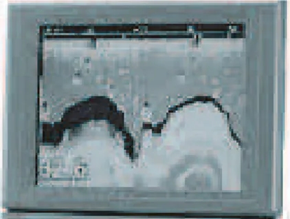
A fishfinder is a marine equipment system that is imple-mented on RTOS. The fishfinder kicks a TX pulse period-ically, collects a sequence of echo signals, it stores in the memory, and processes the stored data for display as an image on the color liquid crystal display (Figure 2) [9]. The screen scrolls from right to left every time the se-quence of data is collected. A user can set parameters such as the depth range and the display mode.
We use two modules of the simplified fishfinder, a flash memory backup module and a sonar control module. For each module, we construct a model on the framework described in the previous section so that the behavior of the actual system can be simulated as far as possi-ble and verify the deadlock-freeness on this model. The experimental environment consists of a 1.60 GHz IntelR PentiumRM, with a 597 MHz bus and 224 MB of RAM.
3.2
Flash Memory Backup Module
3.2.1 Modeling
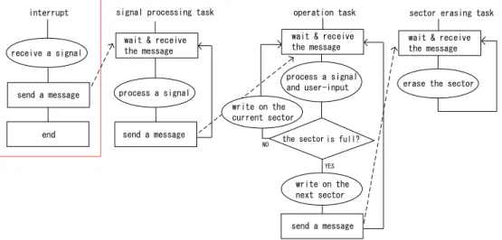
In this module, when the collected echo signals and user’s input for parameter settings are given, they are written onto a proper sector of the memory. A sector consists of multiple data structures. If the sector is full and there is no fresh data structure, then another sector is used. The full sector is erased and reset for use. This module consists of one interrupt handler and three tasks: signal processing task, operation task, and sector erasing task (Figure 3), the priorities of which are in the same order
(signal processing task is the highest) and their behaviors are described as follows:
• Interrupt handler
Interrupt handler may occur at any instant when it receives external signal data. The interrupt handler activates the scheduler and sends a message to the signal processing task.
• Signal processing task
After activation, this task immediately transits to the WAIT state. When this task receives the sage, it processes the signal data, sends the mes-sage to the operation task, and transits to the WAIT state.
• Operation task
After activation, this task immediately transits to the WAIT state. When this task receives the mes-sage, it processes the signal data and the user’s in-put. This task writes the result of the computation onto the sector of the memory that is currently be-ing accessed. If there is no fresh data structure in the sector, then the data is written onto another sec-tor. At the same time, this task sends the message of erasing to the sector erasing task and transits to the WAIT state.
• Sector erasing task
After activation, this task immediately transits to the WAIT state. When the message is received, this task eliminates all of the contents of the full sector and transits to the WAIT state.
In the implementation of this model, message passing be-tween tasks is realized by the functions defined in the framework. We set the number of data structures of a sector as 3000 in our model, considering that, in an ac-tual system, the size of a sector is 64 Kbytes and the size of each data to be written is 20 bytes.
3.2.2 Verification and Analysis
We verify such property that data-writing onto the mem-ory always succeeds. We describe this property as the safety: “no state occurs in which data is written onto the full sector,” which is expressed in the form of the LTL formula:
[]!(sector0_is_full && sector1_is_full && writing)
Figure 3: Flash memory backup module
frequent input occurs, and the data is written on the memory before the full sector is erased. This may occur when the signal processing task and the operation task run continuously, while the sector erasing task is seldom permitted to run.
Figure 4 shows the correct behavior and the incorrect behavior for this process. In Figure 4(a), task 3 is sched-uled at time t, since tasks 1 and 2, which have higher priority, are in the WAIT state. On the other hand, in Figure 4(b), task 1 is scheduled at time t since it is in the EXECUTABLE state. Task 2 is scheduled afterwards and task 3 cannot run. In most cases, the system behaves as shown in (a). However, if a frequent interrupt occurs, then the system may behave as shown in (b). This bug is judged as a false-positive since the speed of erasing is actually much faster than that of data collection.
3.3
Sonar Control Module
3.3.1 Modeling
This module is characterized by a cyclic behavior involv-ing kickinvolv-ing a TX pulse periodically, collectinvolv-ing the se-quence of the echo signals and storing the sese-quence in the memory, and processing the stored data to display this image.
The period of a kick is set in advance and the TX timer is activated on kicking and ensures that the next kick does not occur until the allocated time expires. One echo returns for every TX pulse. When a defined number of echo signals are collected, image processing on the data is performed and the result is displayed on screen.
This module consists of the hardware, two interrupt han-dlers and two tasks: kick TX task and data processing task (Figure 5), the priorities of which are in the same
order (kick TX task is higher) and their behaviors are described as follows:
• TX timer (hardware)
If the current time exceeds the budgeted time, the TX timer interrupt handler is activated.
• TX timer interrupt handler
The TX timer interrupt handler stops the TX timer and sends a message to the kick TX task.
• Data collection interrupt handler
The data collection interrupt handler judges whether the pdefined number of echo signals have been re-ceived. Once all of the data are collected, they are stored in the memory, eventually turning on the flag that indicates the completion of data storage. There-after, the data collection interrupt handler sends the message to the data processing task.
• Data processing task
After setting the initial parameters, such as the pe-riod of kicking TX, the data processing task sends the message to the kick TX task, and then transits to the WAIT state and waits for a message from the data collection interrupt. Next, when the data pro-cessing task receives the message from the data col-lection interrupt, it resets the parameters and sends the message to the kick TX task. The data process-ing task then displays the image of the echo data, transits to the WAIT state and waits for a message from the data collection interrupt.
• Kick TX task
tran-task1: signal processing task task2: operation task task3: sector erasing task
(a) correct behavior
scheduler task1 task2 task3
task1
task2
task3
task1 interrupt
t
(b) incorrect behavior
scheduler task1 task2 task3
task1
task2
task1
task2 interrupt
t message passing
scheduled task
executable
run
Figure 4: Scheduling of tasks
sits to the WAIT state and waits for the message from the TX timer interrupt.
The state in which a task receives a message is nondeter-ministic. In Figure 5, the dotted lines show an example of timing at which the kick TX task receives the messages. A message sent to a task is stored in the messagebox of the task if the task is not in the state in which it can pro-cess the message. If a message arrives at the task when another message exists in the messagebox, then any mes-sage that arrives later is abandoned.
In the implementation of this model, a message passing between tasks is realized by the functions defined in the framework.
3.3.2 Verification and Analysis
We verify such property that deadlock never occurs. We describe this property as the safety: “the system never reaches the state in which neither of two tasks is exe-cutable and no interrupt handler occurs.” The task is not executable if there is no message in the messagebox in the WAIT state. Therefore, this property is expressed in the form of the LTL formula:
[]!(DataProcTask_WAIT && KickTXTask_WAIT && no_mes_queue &&
TXtimer_timerCheck && no_timer_set && DataCol_echoCheck && no_echo_pulse)
The verification fails and a counterexample is generated in the 232nd step. The used CPU time is 0.151 sec-onds. The counterexample corresponds to the situation in which the kick TX task receives a message from the TX timer interrupt handler and a message from the data pro-cessing task before acknowledging one of the messages; the message that arrives later is discarded. In this situ-ation, the kick TX task can no longer receive the second
inline send_msg(id,sig){
if ::msg_queue[id]==true -> skip; ::else -> msg_queue[id]=sig;
if
::task_state[task_id[id]]==wait -> task_state[task_id[id]]=executable; ::else -> skip;
fi;
process_in_active=scheculer; fi;
}
inline rec_msg(id){ do
::msg_queue[id]==true ->
task_id[id]=process_in_active; msg_queue[id]=false;
break;
::msg_queue[id]==false ->
task_id[id]=process_in_active; task_state[task_id[id]]=wait; process_in_active=scheduler; od;
}
Figure 7: Correct implementation of the messagebox
message while it waits for the message. This causes the deadlock. Figure 6 shows the correct and the incorrect behaviors of the kick TX task.
Figure 5: Sonar control module
(a) correct behavior (b) incorrect behavior
4
Discussions
There have been few studies on the verification of embed-ded software systems by a model checker.
Aoki constructed a library of service calls implemented in µITRON on a RTOS using PROMELA and applied it to the verification of the priority inversion problem [1]. The goal of his research was to construct a general library applied to RTOS rather than to verify a specific system.
Cofer et al. applied SPIN to modeling and analyzing the time partitioning features in the scheduler of Avion-ics RTOS [8][16]. They implemented the basic elements of the interrupt handler, the timer, and the scheduler in PROMELA. The relationships of activations between tasks and the scheduler of their target system are differ-ent from those used in the fishfinder. We realized the relationships using the functions of message passing to and from the messsageboxes.
In embeddeing software, the actual system behaves along continuous time, while a model checker like SPIN handles the discrete time, which causes the difficulty in construct-ing a model. It is more desirable to realize a clock in the model. Mizuguchi et al. applied the model checking method to the time-dependent software using NuSMV [6], an extension of SMV, by adopting the concept of a unit time in modeling the timer [15]. While their work was challenging, they showed no results of checking the prop-erties related to real time.
The clock variable can be easily introduced in UP-PAAL [14] and the other tools based on timed automata. Campos et al. discussed the time-sensitive characteristics and schedulability of real-time industrial systems [4] and proposed an algorithm for computing the exact bounds on the delay between two specific events based on sym-bolic model checking. Krichen et al. shows the verifi-cation of real-time systems using timed automata [12]. They proposed a black-box conformance testing frame-work with the introduction of the concept of a clock. However, their target system has neither multiple tasks nor a scheduler. Larsen et al. also proposed a tool for black-box conformance testing of an embedded software based on timed-automata [13]. They introduced a clock variable and showed the results of testing. However, a model checker such as UPPAAL and the tools based on timed automata easily fall into the state explosion in the verification, compared to SPIN, and a user has to contrive harder.
5
Conclusion
We have modeled and verified a simplified fishfinder im-plemented on RTOS using the model checker SPIN. There have been no studies which apply formal method to veri-fying the behavioral correctness of marine equipment
sys-tems.
To sum up our work:
• Constructed a framework using SPIN that can
man-age the behavior of RTOS.
• Constructed a model that simulates the behavior of
a fishfinder on the framework and confirmed the use-fulness of the framework.
• Verified the deadlock-freeness of the system, i.e.,
per-formed bug detection and verified the validity of the corrected version.
In the future, we consider the introduction of a temporal component and intend to provide a method to handle the time-dependent properties.
References
[1] T. Aoki and T. Katayama, “Model Checking Library for Software Based on RTOS,” Embedded Software Symposium 2005, 2005, (In Japanese).
[2] B. Berard, M. Bidoit, A. Finkel, F. Laroussinie, A. Petit, L. Petrucci, P. Schnoebelen and P. McKen-zie (eds.). “Systems and Software Verification: Model-Checking Techniques and Tools,” Springer, 2001.
[3] D. Bosnacki and S. Edelkamp (eds.), “Model Check-ing Software: 14th International Spin Workshop,” LNCS Vol.4595, Springer, 2007.
[4] S. Campos, E. Clarke, M. Marrero and M. Minea. “Timing Analysis of Industrial Real-Time Systems.” InProceedings of the first Workshop on“Industrial-Strength Formal Specification Techniques, pp.97– 107, 1995.
[5] A. M. K. Cheng. Real-Time Systems: Scheduling, Analysis, and Verification. Wiley-Interscience, 2002.
[6] A. Cimatti, E. Clarke, E. Giunchiglia, F. Giunchiglia, M. Pistore, M. Roveri, R. Sebastiani and A. Tacchella. “NuSMV2: An OpenSource Tool for Symbolic Model Checking,” InProceeding of the 14th International Conference on Computer-Aided Verification (CAV’2002),2002.
[7] E. M. Clarke and J. M. Wing, et.al., “Formal Meth-ods: State of the Art and Future Directions”ACM Computing Surveys,Vol.28, No.4, 1996.
[9] Furuno Electric Corporation,
http://www.furuno.co.jp/product/marine/
[10] G. J Holtzmann, “The SPIN The Model Checker,” Addison-Wesley, 2003.
[11] C. Kern and M. R. Greenstreet, “Formal Verification in Hardware Design: A Survey,”ACM Transactions on Design Automation of Electronic Systems,Vol.4, pp.123–1943, 1999.
[12] M. Krichen and S. Tripakis, “Black-Box Confor-mance Testing for Real-Time Systems,” In Model Checking Software: 11th International SPIN Work-shop, LNCS Vol. 2989, Springer, 2004.
[13] K. G. Larsen, M. Mikucionis, B. Nielsen and A. Skou, “Testing Real-Time Embedded Software Using UPPAAL-TRON: An Industrial Case Study,” InProceedings of the 5th ACM international confer-ence on Embedded Software, pp.299–306, 2005.
[14] K. G. Larsen, P. Pettersson and W. Yi, “UPPAAL in a Nutshell,” In International Journal on Soft-ware Tools for Technology Transfer, Vol.1, No.1-2, pp.134–152, 1997.
[15] D. Mizuguchi and H. Watanabe, “A Case Study of Applying Model Checking to Embedded Software Development,” Computer Software, Vol.22, No.1, pp. 77–90, 2005 (In Japanese).
[16] M. Rangarajan, S. D.-Brown, K. Schloegel and D. Cofer. “Analysis of Distributed Spin Applied to Industial-Scale Models.” In Model Checking Soft-ware: 11th International SPIN Workshop, pp.267– 285, LNCS Vol.2989, Springer, 2004.
[17] F. Thoen and F. Catthoor, “Modeling, Verification and Exploration of Task-Level Concurrency in Real-Time Embedded Systems,” Kluwer Academic Press, 2000.