Modular Multipliers Using a Modified Residue
Addition Algorithm with Signed-Digit Number
Representation
Shugang Wei
∗Abstract— In this paper, we present multipliers us-ing a modified addition algorithm modulo m with a signed-digit(SD) number representation where m =
2n
−1,2nor2n+ 1. To simplify an SD modular adder, new addition rules are proposed for generating the in-termediate sum and carry with a binary number rep-resentation. By using the new codes for intermediate sum and carry and the end-around carry architecture, the proposed modulo m addition requires less hard-ware and short delay time for the residue addition than previous methods. A modulo m multiplier can be implemented by a binary modulo m adder tree. Compared to previous work, the circuit area and de-lay time of the multiplier are improved by 21% and
30%, respectively.
Keywords: Residue number system, Signed-Digit Num-ber, Residue arithmetic, modular addition, modular multiplier
1
Introduction
A residue number system(RNS) featuresith residue digit of sum, difference and product is exclusively dependent on the ith digits of the operands [1],[2]. In general, to compute a remainder, it is usually to use read-only mem-ories to do residue arithmetic [3]. However, to store all residue arithmetic tables, many read-only memories are required. Moduli 2n,2n −1,2n + 1 have been widely
used to simplify the residue arithmetic without memory. When a binary number system is used to perform the residue arithmetic, the carry propagation will arise in-side the residue digits and the speed of arithmetic oper-ation will be limited. For example, the residue addition time is proportional to log(n) even for the improved adder architectures[4].
Signed-digit(SD) number system [5] offers a carry-free addition. We have presented a novel residue arithmetic hardware algorithm using the SD number representation to implement the residue addition in a constant time and
∗Supported by Grant-in-Aid Research(C)(19500039) from Japan
Society for the Promotion of Science(JSPS). Manuscript submitted November 27 2008. The author is with the faculty of Engineering, Gunma University, Japan 376-8515. Tel/Fax:81-277-30-1824/1826 Email:[email protected]
the residue multiplication using a residue SD adder tree architecture for the symmetric RNS [6]. High speed con-version algorithms between weighted and residue num-bers also have been proposed by using the presented residue SD additions [7]. For moduli 2n,2n−1,2n+1, the
modular addition can be performed with an end-around-carry SD adder[6]. However, in the residue SD adder, a 2-bit code was used to represent an SD number and this leads to that the circuits is very larger than the binary architecture. To simplify an SD adder, in this paper, a binary number representation is used to express the in-termediate sum and carry of SD addition, such that the performance of residue SD adder can be improved. We propose a modified modulomsigned-digit addition algo-rithm which is designed by generating the residue inter-mediate sum and carry with the binary number repre-sentation. By using the modified modulomSD addition algorithm, a high speed multiplier with a residue adder tree can be implemented. Compared with our previous work [6], the evaluation results of hardware performance show that the area and delay time of the multipliers are improved by 21% and 30%, respectively.
2
Preliminaries
A residue number with respect to an odd modulus mis represented by the symmetric set:
lm={−(m−1)/2,· · ·,0,· · ·,(m−1)/2}. (1)
A residue number X can be represented by an n-digit radix-two SD number representation as follows:
x=xn−12n−1+xn−22n−2+· · ·+x0, (2)
where xi ∈ {−1,0,1}, and X can be denoted as
(xn−1, xn−2,· · ·, x0)SD. To simplify the manipulation of
the modular operation in the SD number representation, we enlargelmto the following redundant residue number
set:
Lm = {−(2n−1),· · ·,−(m−1)/2,· · ·0,
· · ·,(m−1),· · ·,(2n−1)}. (3)
Thus,xmust be inLmwhen it is expressed in ann-digit
SD number representation. Obviously,
Table 1: Rules for adding SD numbers
abs(xi)6=abs(yi)
abs(xi) =abs(yi) xpyi×xpyi−1<0 or xpyi×xpyi−1>0 or
(xpyi−1= 0) and (xpyi<0) ((xpyi−1= 0) and (xpyi>0))
wi 0 xpyi −xpyi
ci xpyi/2 0 xpyi
Note: xpyi=xi+yi.
Table 2: New rules for adding SD numbers
abs(xi)6=abs(yi)
abs(xi) =abs(yi) xpyi×xpyi−1<0 or xpyi×xpyi−1>0 or
(xpyi−1= 0) and (xpyi<0) ((xpyi−1= 0) and (xpyi>0)) ui ti−1 ti−1−xpyi ti−1+xpyi
vi ti+xpyi/2 ti ti+xpyi
Note: xpyi=xi+yi.
= (−xn−1,−xn−2,· · ·,−x0)SD
is also in Lm.
[Definition 1] LetX be an SD number representation and m be a modulus. Then x= hXim is defined as an
integer inLm. When|X|m6= 0,xhas one of two possible
values given by equations
x=hYim=|X|m, (4)
and
x=hXim=|X|m−sign(|X|m)×m, (5)
where
sign(s) =
½
−1 s <0 1 s≥0 .
When|X|m= 0 andm= 2n−1, there are three possible
values for x, that is,−m, 0 andm.
The numbers as the intermediate results calculated in
Lm are used for fast residue arithmetic. If necessary for
a final result, they can be converted intolm.
3
Modulo
m
Signed-Digit Addition
3.1
Previous Study
Consider additionx+y, wherex, yare the SD numbers in the n-digit SD representation shown in (2), can be performed as follows: Letwi and ci be the intermediate
sum and the carry ofith digit position, respectively. The values of them are determined by Table 1 with respect to the values of xi, yi, xi−1, yi−1. In Table 1, abs(xi)
is the absolute value of xi and xpyi = xi +yi. Thus
the addition at each digit can be implemented by the
following two steps:
ADD1: Determineci andwi using Table 1, and
2×ci+wi=xi+yi. (6)
ADD2:
si=wi+ci−1, (7)
wherec−1= 0 andx−1=y−1= 0. Then
S=x+y = (cn−1, sn−1, sn−2,· · ·, s0). (8)
Letµbe a residue parameter and defined as
µ=m−2n. (9)
In this cases of µ ∈ {0,1,−1}, an end-around-carry SD adder is constructed for the modulomsigned-digit addi-tion:
c−1=hcn−12nim=−cn−1×µ (10)
and
x−1 = −µ×xn−1, (11)
y−1 = −µ×yn−1. (12)
Using the above values of c−1,x−1 and =y−1 instead of
c−1= 0 andx−1=y−1= 0, we have
s=hx+yim = (sn−1, sn−2,· · ·, s0). (13)
Figure 1 illustrates a circuit diagram of ann-digit Modulo
ADD1
ADD2
ADD1
ADD2
ADD1
ADD2
s s1
x y
0 0
1
c1 c0 x1y 0
cn-1 n-1 xn-1y xn-2yn-2
SDFA
sn-1
c
-1
w0
w
1
wn-1
x-1y-1
z
n
−µ
Figure 1: Modulom Signed-Digit adder
3.2
Improved Signed-Digit Adder
For the circuit design, an SD digit d ∈ {−1,0,1} is en-coded as a 2-bit binary code d= [d(s), d(a)], whered(s) is the sign andd(a) is the absolute value. Thus, the area of the addition circuit is larger than the binary number architecture. To modify the area cost, a method using the binary number representation for the intermediate carry and sum for the SD addition can be considered.
We useti∈ {0,1} to express the sign ofxi+yi as
ti=
½
1 xi+yi <0
0 xi+yi≥0 .
Then, we modify Table 1 by
ui = ti−1−wi (14)
vi = ti+ci (15)
and new rules for the SD addition are shown in Table 2. We can show thatui ∈ {0,1} and vi ∈ {0,1} as follows:
In the case of abs(xi) = abs(yi), ui = ti−1 and vi = ti+ (xi+yi)/2∈ {0,1}, becauseti= 1 whilexi+yi=−2
and ti = 0 while xi+yi = 2. When abs(xi) 6= abs(yi)
and (xi+yi)×(xi−1+yi−1)<0, we have ui =ti−1−
(xi+yi) ∈ {0,1} from the facts that ti−1 = 1 while
xi+yi = 1 and ti−1 = 0 while xi+yi = −1. When abs(xi)6=abs(yi) and (xi+yi)×(xi−1+yi−1)>0, we
also have ui = ti−1+ (xi+yi) ∈ {0,1} from the facts
that ti−1 = 1 while xi +yi = −1 and ti−1 = 0 while
xi+yi = 0. When xi−1+yi−1 = 0 and xi+yi =−1, ui = ti−1−(xi+yi) = 1, and when xi−1 +yi−1 = 0
and xi+yi = 1, ui = ti−1 + (xi+yi) = 0. Thus, it
is always true that ui ∈ {0,1}. For vi = ti+ci, when
(xi+yi)/2 = 1 orxi+yi= 1,ti= 0 and vi= 1. When
(xi+yi)/2 =−1 orxi+yi=−1,ti = 1 andvi∈ {0,1}.
Whenxi+yi= 0,ti= 0 andvi = 0. Thus,ui∈ {0,1}.
Therefore, we can modify the signed-digit addition and perform the following two steps at each SD digit position:
ADD1∗: Calculateui andvi by Table 2 meeting
ui = ti−1−wi (16) vi−1 = ti−1+ci−1. (17)
x
n-1 xn-2 x1 x0
y
n-1 yn-2 y1 y0
t
0-w1 t-1-w0
t
n-2-wn-1 tn-3-wn-2
t
n-3+cn-3 t0+c0
t
n-1+cn-1 tn-2+cn-2
U
V t
n-1
+w
n-1
c
n-2
c
n-1
+w
1
c
0 w0
t
-1
V-U +w
n-2
c
n-3
+
:
:
:
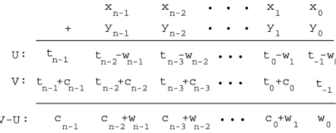
Figure 2: Improved signed-digit addition
ADD2∗: Addvi
−1 to−ui that meets
si=ci−1+wi=vi−1−ui, (18)
Then we have
S = V −U
= (vn−1, vn−2,· · ·, v0, v−1)
−(un, un−1,· · ·, u1, u0)
= (tn−1+cn−1, tn−2+cn−2,· · ·, t0+c0, t−1)
−(tn−1, tn−2−wn−1,· · ·, t0−w1, t−1−w0)
= (cn−1, cn−2+wn−1,· · ·, c0+w1, w0)
= (sn, sn−1, sn−2,· · ·, s0)
= x+y, (19)
where v−1 = t−1 = 0 and the calculating diagram is
shown in Fig. 2. Note that a new carry is not generated in ADD2∗ similar as ADD2, and the values ofu
i andvi
are decided directly from the values of xi, +yi,xi−1 and
yi−1.
In Table 1,wiandciare in the SD number representation
such that we have to use 2-bit binary codes to represent them. However, in Table 2, we use the binary number representation to representui andvi, so that the
perfor-mance of the circuits implementing ADD1∗ and ADD2∗ can be improved.
3.3
New Modulo
m
Signed-Digit Adder
We now consider how to deal with the residue operation modulo m, where m = 2n +µ and µ ∈ {−1,0,1}. By
using the relationships ofx−1=−µ×xn−1,y−1=−µ×
yn−1andtn−1, the value oft−1 is obtained from the sign
of −µ×(x−1+y−1). Then, the modulo m signed-digit
addition can be expressed as follows.
hSim = hX+Yim=hhVim− hUimim
= (vn−2−un−1,· · ·, v0−u1, v−1−u0).(20)
In equation (20), the digits ofU andV includingv0and
u−1 at 0-th digit position can be determinated by the
rules of Table 2. However,u0andv−1on the
i : 4 3 2 1 0
a : 1 0 -1 1 1 b : 1 1 -1 0 0 (ADD1)
w : 0 1 0 -1 -1 c : 1 0 -1 1 1 1
(ADD2)
z : 0 0 1 0 0
i : 4 3 2 1 0
a : 1 0 -1 1 1 b : 1 1 -1 0 0 (ADD1)
w : 0 1 0 -1 1 c : 1 0 -1 1 0
(ADD2)
z : 0 0 1 -1 1
i : 4 3 2 1 0
a : 1 0 -1 1 1 b : 1 1 -1 0 0 (ADD1)
w : 0 1 0 -1 1 c : 1 0 -1 1 0 -1
(ADD2)
z : 0 0 1 -1 0
m=31 m=32 m=33
i : 4 3 2 1 0
a : 1 0 -1 1 1 b : 1 1 -1 0 0
u : 0 0 0 1 1 v : 0 0 1 1 1
z : 0 0 1 0 0
i : 4 3 2 1 0
a : 1 0 -1 1 1 b : 1 1 -1 0 0
u : 0 0 0 1 1 v : 0 0 1 1
z : 0 0 1 0 -1
i : 4 3 2 1 0
a : 1 0 -1 1 1 b : 1 1 -1 0 0
u : 0 0 0 1 0 v : 0 0 1 0 0
z : 0 0 1 -1 0 (a) Addition using prevous algorithm
m=31 m=32 m=33
(b) Addition using new algorithm (ADD1*)
(ADD2*)
(ADD1*)
(ADD2*)
(ADD1*)
(ADD2*)
Figure 3: Example of Modulom signed-digit addition. algorithm.
ADD1∗∗: Determineu0 andv
−1 by Table 2, meeting
u0 = t−1−w0 (21)
v−1 = t−1−µ×cn−1, (22)
where
t−1=
½
1 −µ(xn−1+yn−1) <0
0 −µ(xn−1+yn−1)≥0 .
Because we use the binary number representation instead of the signed-digit number representation for the interme-diate sums and carries, the new modulo m signed-digit addition can achieve high speed and small circuits.
Example 1 : Let n = 5, a = (1,0,−1,1,1)SD and b = (1,1,−1,0,0)SD. Thus, a= 15 and b = 20, and in
the case of µ= 1m= 25+ 1 = 33. We havet
0= 0, t1=
0, t2 = 1, t3 = 0, t4 = 0 and t−1 = 1. By the rules of
Table 2, ui and vi are determined. Fig.3(b) illustrates
the calculation of hx+yim using the new algorithm for m= 31,32 andm= 33. The results areh15 + 20i31= 4,
h15 + 20i32 = 3 and h15 + 20i33 = 2. In Fig.3(a), the
residue addition process is also shown by the previous algorithm.
4
Modulo
m
SD Multipliers
To calculatehx×yim, wherexandyare integers in then
-digit radix-2 SD number representation,x×yis expanded as follows:
x×y = (xn−12n−1+xn−22n−2+· · ·+x0)
×(yn−12n−1+yn−22n−2+· · ·+y0)
=
n−1
X
i=0
yi2i×(xn−12n−1+xn−22n−2
+· · ·+x0).
We have
hx×yim = h n−1
X
i=0
hyi2i×(xn−12n− 1
+xn−22n− 2
+· · ·+x0)imim
= h
n−1
X
i=0
ppiim, (23)
where
ppi=hyi2i×(xn−12n−1+xn−22n−2+· · ·+x0)im (24)
denotes as a partial product. Sinceyi ∈ {−1,0,1}, ppi = yih2i×(xn−12n−
1
+xn−22n− 2
+· · ·+x0)im
= yi×sxi, (25)
where
sxi=h2i(xn−12n− 1
+xn−22n− 2
+· · ·+x0)im. (26)
Therefore, a modulo m multiplication can be imple-mented by calculating Eqs.(26).(25) and (23) to obtain partial products and the sum of the partial products.
In the cases ofµ= 0 and µ=±1,
sxi = (xn−i−1, xn−i−2,· · ·, x0,
x
n-i-1x
n-i-2x
0x
n-1x
n-iy
ipp
i−µ −µ
Figure 4: A partial product generating unit
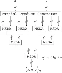
Partial Product Generator
MSDA MSDA MSDA MSDA
MSDA MSDA
MSDA
x y
x y m
:n digits
Figure 5: Modulo mSD multiplier with an MSDA tree.
Thus, a partial product is simply obtained by ani-digit end-around-shift and ann-by-1 digit multiplication. The
i-digit end-around-shift by directly wiring correspond in-put and outin-put signals can performed in a constant time.
A binary tree of the modulo m SD adders can be con-structed for the modulo m sum of the partial products as shown in Fig.5. The modulom circuit for the shifted number may be constructed by the AND-OR two-stage logical network which has a constant delay time. How-ever, the circuit may be very complicated for a large n. the modulommultiplications can be performed in a time proportional to log2n.
5
Hardware
Realization
and
Perfor-mance Evaluation
We use a hardware description language, VHDL, to de-sign the residue arithmetic circuits, for the implementa-tion of the proposed algorithm.
ADD1**
ADD2*
ADD1*
ADD2*
ADD1*
ADD2*
s s1
x y
0 0
1
v1 v0 x1y 0
vn-1 n-1 xn-1y xn-2yn-2
SDFA
sn-1
vn-1
u0
u
1
un-1
x-1y-1
Figure 6: New ModulomSigned-Digit adder
Table 3: Binary representation for a radix-two signed digit.
ai ai(1) ai(0)
-1 1 1
0 0 0
1 0 1
We specify a binary representation for a radix-two signed-digitaias Table 3, whereai(1) is the sign andai(0) is the
absolute value of ai. Thus, ap-digit radix-2 SD number ais represented by a vector with 2p-bit length.
a = (an−1, an−2,· · ·, a0)SD
= [an−1(1)an−1(0) an−2(1)an−2(0)
· · ·a0(1)a0(0)] (27)
For example, (1,0,0,−1)SD = [01000011]. Figure 6
il-lustrates a circuit diagram of the new MSDA, where
µ ∈ {−1,0,1}. One SDFA consists of sub-circuits, ADD1∗and ADD2∗, and in the most significant position ADD1∗∗is designed for the end-around-carry generation.
ui andvi generated by ADD1∗or ADD1∗∗ are in the
bi-nary number representation. si=vi−1−ui is performed
in ADD2∗andsi∈ {−1,0,1}. The whole design has been verified by 1-µm CMOS gate level simulation. The delay times and gates of the design results are aummarized in Tables 4 and 5. Because the proposed MSDA is designed with binary number representation except input and out-put, we have small circuits and speed-up of computation time.
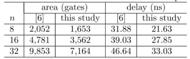
Compared to our previous work, the circuits are im-proved by 21% and the computation times are shorten by 30%. The new residue SD adder can be applied to a residue multiplier and the delay time and hardware cost of the multiplier can be also improved by about 30% and 20%, respectively. We also designed fast binary residue adders[8] for the performance comparison with the pre-sented SD adders. The proposed addition is high-speed for large wordlength residue additions.
Table 4: Performance of modulo 2n+ 1 adders
area (gates) delay (ns)
n [6] [8] this study [6] [8] this study 8 274 213 215 7.47 6.34 5.22 16 530 612 415 7.47 9.03 5.22 32 1,016 1,744 823 7.47 12.86 5.22
Table 5: Performance of modulo 2n+ 1 multipliers
area (gates) delay (ns)
n [6] this study [6] this study 8 2,052 1,653 31.88 21.63 16 4,781 3,562 39.03 27.85 32 9,853 7,164 46.64 33.03
m SD adders is very high speed. For the design of RNS chips, the modulo mSD adders and multipliers may be pre-designed with VHDL and are used as functional cells.
6
Conclusion
A new algorithm of modulo m SD adder has been pre-sented. The binary number coding is used for achieving the high speed residue SD addition. A high speed residue multiplier can be constructed with a binary MSDA tree for the high speed calculations or only with one MSDA for a compact structure. Thus the modulom multiplica-tion is performed in a time propormultiplica-tional to log2pby using
the binary adder tree.
High-speed computations can be performed based on the assumption that input and output data of the residue arithmetic circuits are in the residue SD number form, because some computing system applications, such as digital filtering, require repeated calculations of sums of products before the final results are obtained. For in-tegration with conventional binary systems, efficient cir-cuits are required to convert into and out of the residue SD systems. Our studies also focus on the evaluation of the presented residue arithmetic circuits, and the appli-cation to the computation systems, such as digital signal processing and digital control systems.
References
[1] N.S.Szabo and R.I.Tanaka ,Residue Arithmetic and Its Applications to Computer Technology, New York: McGraw-Hill,1967.
[2] Vassilis Paliouras and Thanos Stouraitis, “Novel High-Radix Residue Number System Architectures,”
IEEE Tran.on circuits and systems II., vol.47,no.10, pp.1059-1073, Oct. 2000.
[3] G.A. Jullien, “Residue number scaling and other op-erations using ROM arrays,”IEEE Trans. Comput.,
vol.C-27, no.4, pp.325-336, April 1978.
[4] L.Kalampoukas, D.nikolos, C.Efstathiou, H.T.Vegos and J. Kakamatianos, “High-Speed Parallel-Prefix Modulo 22−1 Adders,” IEEE Trans. Comp., vol.49,
no.7, pp.673-680, 2000.
[5] A.Avizienis, “Signed-digit number representations for fast parallel arithmetic,”IRE Trans. Elect. Com-put., EC-10, pp.389-400, 1961.
[6] S.Wei and K.Shimizu,” Residue Arithmetic Circuits Using a Signed-Digit Number Representation”, Pro-ceedings of the IEEE 2000 International Symposium on Circuits and Systems, Vol.-I, pp.24-27, 2000.
[7] S. Wei and K. Shimizu: A New RNS to Mixed-Radix Number Converter Using Modulo (2p−1)
Signed-Digit Arithmetic, Proceedings of 2004 IEEE Asia-Pacific Conference On Circuits and Systems, vol. 1, pp.377-380, 2004.
[8] C.Efstathiou, H.T. Vergos and D.Nikolos, “ Modulo 2n ±1 Adder Design Using Select Prefix Blocks”,