Article
Printed in Brazil - ©2017 Sociedade Brasileira de Química0103 - 5053 $6.00+0.00*e-mail: [email protected]
Synthesis of Submicrometer Calcium Carbonate Particles from Inorganic Salts
Using Linear Polymers as Crystallization Modifiers
Sara E. Facchinetto, Tanize Bortolotto, Gabrielly E. Neumann, Jean C. B. Vieira, Bryan B. de Menezes, Cristiano Giacomelli and Vanessa Schmidt*
aDepartamento de Química, Universidade Federal de Santa Maria, 97105-900 Santa Maria-RS, Brazil
In this study, we report the synthesis of submicrometer calcium carbonate particles using the simplest approach of mixing solutions of calcium chloride and ammonium carbonate inorganic precursors in the presence of crystallization modifiers. Instead of the typical crystallization of CaCO3 into large calcite crystals with rhombohedral morphology, very small uniform spherical vaterite particles were formed with the addition of small amounts of the anionic homopolymer poly(sodium 4-styrenesulfonate) (PSS). In contrast, large spheres made of a collection of calcite polycrystallite aggregates formed in the presence of poly(acrylic acid) (PAA). Crystal growth in a pre-organized environment created by the selective distribution of CaII ions in the shell of polyestyrene-b-poly(acrylic acid) (PS-b-PAA) core-shell spherical micelles revealed a rather poor control of the size and morphology. Therefore, the PSS anionic homopolymer can be applied to the synthesis of submicrometer CaCO3 particles from solutions of inorganic salts, which is a much cheaper and sustainable method than controlled CO2 gas production and diffusion.
Keywords: nanocomposites, polycaprolactone, calcium carbonate particles, crystallization modifiers
Introduction
One of the most important advances in materials science and engineering is the possibility of reinforcing polymers with cost-effective fillers such as carbon black, clays, silicates and limestone (calcium carbonate). Fillers are added to formulations in order to fine tune the physical and mechanical properties, or simply to reduce the cost of production by decreasing the amount of polymer resin.1
Although calcium carbonate is an abundant naturally occurring mineral already largely used in the polymer industry, recently the clever manipulation of particle size and its effects on the material properties has attracted considerable attention.2-12
Nano- and micrometer calcium carbonate particles can be synthesized by a variety of methods, including controlled gas diffusion, colloidal/microemulsion systems, sonochemistry, hydrothermal synthesis, etc. The simplest approach consists of the precipitation of calcium carbonate from solutions containing inorganic salts as a source of calcium(II) and carbonate ions. In this case, the precipitation of calcium carbonate involves a complex set
of processes of crystal nucleation and growth that is very sensitive to the chemical environment.5 The diverse atomic
arrangements found in calcium carbonate materials (three crystalline polymorphs: calcite, vaterite, and aragonite; two hydrated metastable forms: monohydroxycalcite and calcium carbonate hexahydrate; and an unstable amorphous phase) can therefore be controlled by the addition of appropriate crystallization modifiers. These include metallic ions, surfactants,10,13 biopolymers,2,14-16
and synthetic polymers.2-6,9,17-25 Indeed, crystallization
control is a critical requirement in the synthesis of many important materials.
In this context, it has been demonstrated that synthetic polymers alter the crystallization and they have consequently found extensive application in industry, for instance, as limescale inhibitors in boilers and water pipes. One common feature of polymers able to control the crystallization of calcium carbonate, such as poly(styrene sulfonate)5,9,23 and poly(acrylic acid),4,17,18,26-28 is that they
are anionic (or contain anionic segments) and are therefore capable of interacting with calcium(II) ions and with the crystal surface itself.
conventional ion-by-ion growth. Instead, the crystallization usually begins with the formation of small particles of amorphous calcium carbonate (ACC), which are rapidly converted into more stable structures, particularly into calcite or vaterite primary particles.5,13 Through specific
interaction with functional groups attached to the polymer, these particles are stabilized, thus retarding further growth. They can therefore aggregate and generate diverse morphologies including hollow spheres, spherules, dumbbells and disks, depending on the experimental conditions.
This article describes, for the first time at the best of our knowledge, the synthesis of submicrometer calcium carbonate particles, using the simplest approach of mixing solutions of calcium chloride and ammonium carbonate inorganic precursors in the presence of crystallization modifiers, and their application in the production of nanocomposites. We show how very small uniform spherical particles can be prepared in the presence of small amounts of the anionic homopolymer poly(sodium 4-styrenesulfonate) (PSS). Under the same experimental conditions, we studied the effects of different polymer structures containing the carboxylic group (linear poly(acrylic acid); PAA), and of a pre-organized environment created by the selective distribution of CaII ions.
The surface-modified submicrometer calcium carbonate particles were then used to produce poly(ε-caprolactone) (PCL) composites. PCL has been attracting solid investment aimed at developing biodegradable polymeric materials.29,30
It is well-known that for most applications PCL-based materials require blending with other resins or filling with inorganic particles to further improve the processing and mechanical properties.29-33 Oscillatory rheology of
PCL/polymer@CaCO3 composites, where polymer@CaCO3
refers to CaCO3 nanoparticles coated with a polymer,
in the melt state was used to establish the effects of polymer@CaCO3 particles on the characteristic behavior
of PCL.
Experimental
Materials
Calcium chloride, calcium nitrate, sodium carbonate, ammonium carbonate, poly(sodium 4-styrenesulfonate) (PSS, weight-average molecular
weight (Mw) = 70,000 g mol-1) and
polyestyrene-b-poly(acrylic acid) (PS60-b-PAA30, Mw = 8,400 g mol-1) were
acquired from Sigma-Aldrich Co., and used as received. Poly(acrylic acid) (PAA, Mw = 7,200 g mol-1) was obtained
after hydrolysis of poly(terc-butyl acrylate), which was
synthesized by RAFT (reversible addition-fragmentation chain transfer) polymerization following a procedure reported earlier.34
Particle synthesis
Synthesis of polymer@CaCO3 particles
In a typical experiment, calcium chloride was added to a previously prepared aqueous solution containing the homopolymer, which was first dissolved in water by direct dissolution. The resulting solutions contained 0.1 mol L-1
CaCl2 and the polymer at different concentrations, as
specified below. To this solution, 0.1 mol L-1 (NH 4)2CO3
was added dropwise. During this process, the temperature was kept constant at 25 °C using a jacketed vessel. Immediately after the addition of (NH4)2CO3, the resulting
solution was centrifuged at 12,000 rpm for 2 h, and the precipitate was washed first with water and then with ethanol. Finally, solid samples were dried in a heated oven at 75 °C for 24 h. When indicated, the temperature was raised to 80 °C (heating rate = 5 °C min-1) after
the addition of the (NH4)2CO3 was completed, and kept
constant for 140 min.
Physical methods and techniques
Fourier transform infrared spectroscopy (FTIR)
KBr pellets were prepared using 2-3 mg of polymer@CaCO3 particles. Background corrected spectra
were recorded using a Bruker Tensor-27 spectrometer with 4 cm-1 of resolution.
Powder X-ray diffraction (XRD)
XRD data were collected on a Bruker D8 Advance diffractometer with Cu Kα radiation (λ = 1.54184 Å) using a nickel absorber to filter Kβ radiation with a LYNXEYE XE 1-D detector. The measurement range was from 20º to 60º 2θ angles with a step size of 0.02 degree and an exposure time of 500 ms per step.
Thermogravimetric analysis (TGA)
TGA runs were conducted using a TA Instruments Q5000 apparatus at a heating rate of 10 °C min-1 from room
temperature to 700 °C. The nitrogen flow was maintained at 50 cm3 min-1 during the analysis.
Scanning electron microscopy (SEM)
the stub were gold coated on an ion sputter. SEM images were acquired using a JEOL 55 M6360 microscope at an accelerating voltage of 20 kV.
Rheology
Rheological experiments were carried out on a stress-controlled rheometer (TA Instruments AR-G2) equipped with an environmental test chamber (ETC). The ETC was fitted with a standard parallel plate geometry accessory kit suitable for thermoplastics and rubbers. The composite material was loaded onto the plate equilibrated at 100 °C
for 15 min. Subsequently, the gap was then closed to 100 µm using the exponential sample compression mode. The ETC chamber was then opened, and the excess sample was trimmed using a flat-ended tool while the bearing was locked to prevent rotation. Prior to the experiments, a conditioning step was applied to the sample by setting the temperature at 100 °C for 15 min at rest. Initially, a strain
amplitude of 5% was applied in all dynamic tests to ensure that the deformation was within the linear viscoelastic regime. The linear viscoelastic region was determined by a strain sweep from 0.1 to 5% performed at a frequency of 1 Hz at 100 °C. Frequency sweeps were run at 100 °C
over an experimental range of 0.06 to 628 rad s-1 and the
values for the viscoelastic properties, storage modulus (G’) and loss modulus (G”) were determined. The polymer molecular structure dictates the magnitude and shape of the G’ and G” curves. Steady-state flow experiments were performed within the shear rate range of 0.01-10 s-1.
Results and Discussion
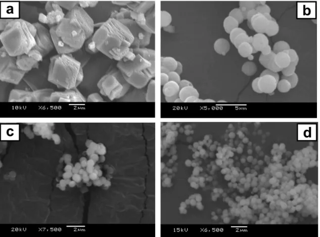
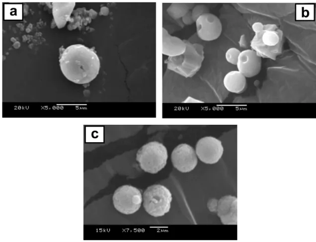
The presence of PSS molecules in the crystallizing solution promoted a significant change in the morphology of the precipitated calcium carbonate inorganic particles (Figure 1). The SEM image of CaCO3 obtained in the
absence of PSS (Figure 1a) revealed the formation of large crystals with rhombohedral morphology, as expected under these experimental conditions.6 On the
other hand, smaller particles with spherical morphology were obtained when precipitation occurred in the presence of PSS. As the homopolymer concentration increased (Figures 1b to 1d), the precipitated particles preserved their morphology, but the size decreased significantly, that is, to the submicrometer range (from ca. 4 down to 0.8 µm). The uniformity of both the shape and size of the spherical structures is a remarkable feature of such samples, as observed in Figure 1d.
Figure 1. CaCO3 particles precipitated from solutions containing no additive (a), and PSS@CaCO3 particles grown in the presence of 0.05 (b), 0.10 (c),
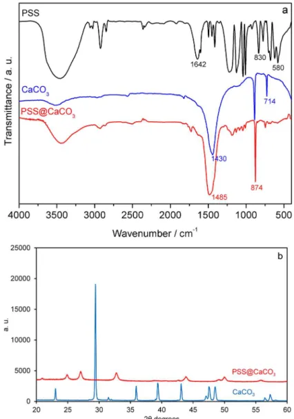
To gain an insight into the effect of this anionic polymer on the modulation of the CaCO3 structure, the calcium
carbonate crystal structure was determined by FTIR35-37 and
the results are shown in Figure 2a. The absorption band at 714 cm-1 is characteristic of the most stable rhombohedral
polymorph (calcite), and is not observed when CaCO3 was
precipitated in the presence of PSS. Instead, the vaterite phase is stabilized under these experimental conditions, as indicated by the absorption band at 745 cm-1.36 Whilst
the addition of PSS modified the interaction between developing particles,19,38 ultimately leading to changes in the
crystal structure of CaCO3 particles from calcite to vaterite,
the polymer concentration effects were limited to the particle diameter variations, that is, no structural changes were identified within the polymer concentration range used in this study. These results were corroborated by XRD data shown in Figure 2b. The measured powder patterns
were compared with the database Powder Diffraction Files (PDF) from the International Center of Diffraction Data (ICDD). The search results PDF 00-005-0586 and PDF 00-033-0268, corresponding to calcite and vaterite, respectively, match exactly with the expected compositions in each powder pattern.
The formation of spherical vaterite particles at a high [Ca]:[S] ratio (3:1) with [Ca] = 33 mmol L-1 and
high polymer concentration is, in fact, favored over polycrystalline calcite aggregates, as noted previously elsewhere.5 However, much to our surprise, the diameter of
the vaterite particles was very small. Samples synthesized in this study consisted of ca. 0.8 to 4 µm diameter particles, which are much smaller than the 20-µm analogs synthesized by Kulak et al.5 using poly(ethylene oxide)-b-poly(sodium
4-styrenesulfonate) amphiphilic block copolymers. This characteristic of the particles leads to the specific surface
Figure 2. (a) FTIR spectra and (b) XRD patterns for neat PSS polymer and CaCO3 particles precipitated in the absence and in the presence of 2.00 mg mL-1
area of this powder being at least two orders of magnitude higher, a feature that could prove attractive for applications in nanocomposite technology.
The formation of small particles (with a few micrometers down to the submicrometer range) has also been reported by Cölfen and Antonietti.3 In their study, the authors
used a much more sophisticated polymer with a double hydrophilic block architecture, and bearing phosphonate groups, to attain crystal design control in the formation of microparticles by precipitation from concentrated calcium cation solutions, similarly to the work carried out in this study.
In the study reported herein, the decrease in the particle size from ca. 4 down to 0.8 µm on increasing the polymer concentration is related to the extent of adsorption of the anionic polyelectrolyte onto the calcium planes. The surface coverage by adsorption increases with the polymer concentration, thus blocking sites essential for the incorporation of a new solute into the crystal lattice, which eventually reduces the crystal growth.38
Besides additives, such as homo- and block copolymers, the temperature can also play a significant role in the control of the calcium carbonate structure.7,20,39 We evaluated the
effect of the temperature on the CaCO3 particle morphology
after the addition of CO32- ions to the solution containing
Ca2+ by raising the temperature from 25 to 80 °C with a
heating rate of 5.0 °C min-1.
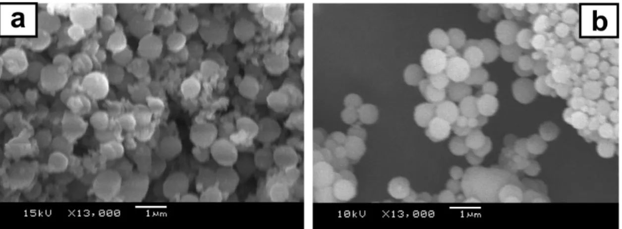
The SEM analysis of CaCO3 samples collected by
crystallization from solutions containing PSS, after heating at 80 °C (Figure 3a), revealed that several particles lost their initial spherical morphology. The particle morphology was clearly heterogeneous, in contrast to particles recovered from the synthesis medium at 25 °C (Figure 1d). Indeed, the FTIR spectrum for the CaCO3 particles sampled from
the solution immediately when the temperature reached 80 °C exhibits a singular feature (Figure 4a); the appearance
of the lattice H2O libration or translation band at 580 cm-1
is indicative of the formation of a CaCO3.xH2O hydrated
phase.40 The water molecules are bound to the inorganic
structure because the intensity of the characteristic band of free water molecules at ca. 3500 cm-1 does not correlate with
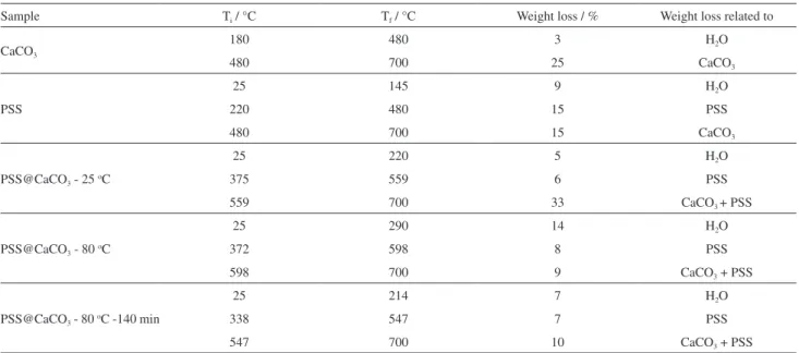
the absorption intensity at 580 cm-1. Thermogravimetric
analysis (Figure 5 and Table 1) confirmed a significant increase in the water content on raising the temperature of the crystallizing solution from 5% (m/m) at 25 °C to 14% (m/m) at 80 °C. The difference in terms of water content can be readily seen from the first weight loss process, which is observed below 200 °C.
The hydrated CaCO3 structure identified soon after
increasing the temperature to 80 °C is, however, not stable. The particles that had lost their spherical shape upon heating clearly recovered it when the reaction mixture was kept at 80 °C for 140 min. This transition is favored by the Figure 3. PSS@CaCO3 particles prepared in the presence of 2.00 mg mL-1 PSS and collected (a) immediately after the solution temperature reached 80 °C
and (b) after 140 min at 80 °C.
Figure 4. FTIR spectra of PSS@CaCO3 particles prepared in the presence
of 2.00 mg mL-1 PSS and recovered at three different stages: immediately
poor stability of the crystalline CaCO3.xH2O phases under
ordinary conditions.41 This process is also accompanied by a
decrease in the average particle diameter from 0.8 to 0.5 µm, as the results shown in Figure 3 reveal. These structural and morphological changes are due to the temperature only, as the material collected at 25 °C either immediately after the addition of ammonium carbonate (standard protocol used in this study) or after 140 min were found to be the same.
The phase selection of calcium carbonate and the morphology of the resulting particles are strongly related to the interaction between the polymer and amorphous precursor developing particles, as the findings obtained in the presence of PAA and PS-b-PAA demonstrate. SEM imaging verified the formation of much larger
polycrystalline spherical particles (Figure 6) when PSS was replaced by PAA under the same experimental conditions (i.e., at high [Ca]:[S] ratio (3:1) with [Ca] = 33 mmol L-1
and high polymer concentration).
The particles consisted predominantly of microspheres made of a collection of calcite polycrystallite aggregates (see Figure 6c), although the samples were somewhat heterogeneous at low polymer concentration (see Figures 6a and 6b). This observation is in agreement with the previously known stability of the calcite structure, with polycrystalline aggregates being more stable than regular microspheres under the specified conditions.5 The calcite
structure was confirmed by the appearance of its typical FTIR absorption bands (see above) on the spectrum of a representative PAA@CaCO3 sample shown in Figure 7a,
as well as by the corresponding XRD pattern shown in Figure 7b.
Interestingly, we observed the presence of holes in almost all of the particles of the samples synthesized using PAA as a crystallizing solution modifier (see Figure 6). The formation of holes in calcite particles has been previously reported by Loges et al.19 In that study, however, particles
were grown over self-assembled monolayers, and the formation of holes was attributed to the adhesion of particles to the surface and their subsequent movement from the original position, thus causing the outer surface to break. In our case, this series of events (i.e., adhesion to the surface followed by breaking away leaving a patch of material on the surface and a hole on the particle) is not present. Cai et al.9 reported the formation of hollow
vaterite nanospheres from amorphous calcium carbonate solid particles, controlled by the presence of PSS and water.
Table 1. Results of thermogravimetric analysis of PSS polymer, CaCO3 precipitate, and PSS@CaCO3 particles
Sample Ti / °C Tf / °C Weight loss / % Weight loss related to
CaCO3
180 480 3 H2O
480 700 25 CaCO3
PSS
25 145 9 H2O
220 480 15 PSS
480 700 15 CaCO3
PSS@CaCO3 - 25 oC
25 220 5 H2O
375 559 6 PSS
559 700 33 CaCO3 + PSS
PSS@CaCO3 - 80 oC
25 290 14 H2O
372 598 8 PSS
598 700 9 CaCO3 + PSS
PSS@CaCO3 - 80 oC -140 min
25 214 7 H2O
338 547 7 PSS
547 700 10 CaCO3 + PSS
Figure 5. Thermogravimetric analysis of PSS polymer and PSS@CaCO3 particles collected at three different stages during the
On applying a much simpler experimental protocol than Cai et al.,9 we did not observe holes in the vaterite particles
prepared in the presence of PSS.
The holes evidenced in the present study in the presence of PAA are attributed to a combination of two effects: (i) local (i.e., at the hole formation site) redissolution of freshly precipitated calcium carbonate, and (ii) osmotic flow. The first effect is due to a local high concentration of PAA that develops inside the particles during precipitation. The dissociation of CaII/PAA complexes is one of the
steps preceding the solid precipitation, and it generates a local increase in the PAA concentration (that is, the PAA is released to the medium and its concentration consequently increases). Under such conditions, freshly precipitated calcium carbonate can then be redissolved in a process governed by equilibrium displacement towards the formation of CaII/PAA complexes at certain points on
the particles, eventually resulting in a hole, which will ultimately serve as a release valve for the high concentration of PAA inside the particle.9 This process is also favored
by the osmotic pressure imbalance that evolves from a combination of osmotic flow and concentration changes. This is not observed in the presence of PSS because of its weaker interaction with Ca2+ cations as compared to PAA.
We also tested the hypothesis that the morphology of calcium carbonate particles can be controlled by letting CaII interact with PAA segments in a volume featuring
some degree of pre-organization. To this aim, a PS-b-PAA linear block copolymer system that self-assembled into core-shell spherical micelles of 25 nm diameter in aqueous solution was used. PAA constitutes the micellar shell, which is also where CaII will preferentially be located
given the favorable CaII/PAA interaction. In spite of
such a strong change in the distribution of CaII ions in
solution, the results revealed a rather poor control of the
PS-b-PAA@CaCO3 particle size and morphology.
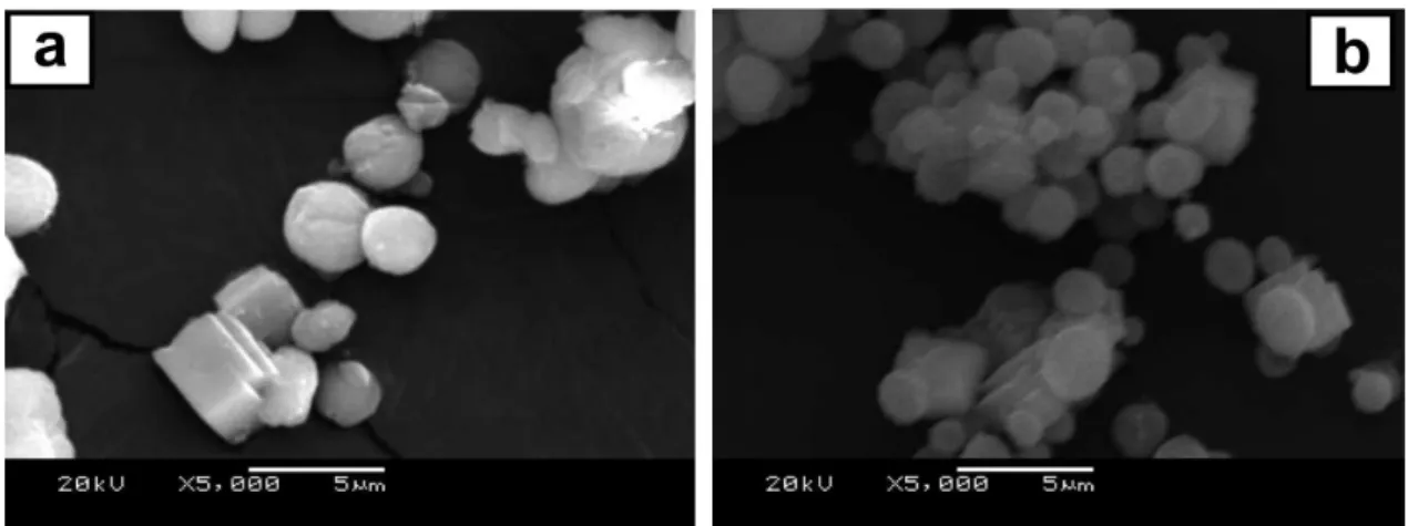
Large crystals with rhombohedral morphology were clearly abundant between the polydisperse spherical particles at any polymer concentration within the range of 0.01-2.0 mg mL-1 (see Figure 8). The FTIR analysis
(Figure 7a) suggested that the samples are composed of calcite (typical IR absorption band at 714 cm-1) and
vaterite (typical IR absorption band at 745 cm-1) phases in
these samples. The XRD results (Figure 7b) confirmed the presence of calcite and vaterite phases.
The representative polymer@CaCO3 particle systems
Figure 7. (a) FTIR spectra and (b) XRD patterns of polymer@CaCO3 particles precipitated from crystallizing solutions containing either 0.10 mg mL-1
PSS, PAA or PS-b-PAA, as indicated.
Figure 8. PS-b-PAA@CaCO3 particles precipitated from solutions containing (a) 0.05 and (b) 0.10 mg mL-1 PS-b-PAA.
accessed by oscillatory rheology. Whilst the effective dispersion of particles in the polymer matrix still
Figure 9. (a) SEM image of a PSS@CaCO3/PCL composite (4% PS@CaCO3), and (b) corresponding relationship between shear stress and shear rate
compared with neat PCL.
was evidenced by SEM imaging. This can be clearly seen in Figure 9a, which shows a typical SEM micrograph of the 4% PSS@CaCO3/PCL composite. Well-dispersed particles
in this sample significantly improve the melt viscosity, that is, by approximately 30% (from 10.2 to 13.5 kPa s).
Conclusions
A strong point of interest in relation to small calcium carbonate particles is the possibility of producing materials with a large surface area. Based on the results of this study, we conclude that submicrometer calcium carbonate particles can be synthesized from very simple inorganic salts, without the need to generate CO2 gas in situ, using
homopolymers as the crystallization modifiers. This can be achieved in the presence of small amounts of the anionic homopolymer poly(sodium 4-styrenesulfonate) (PSS). The vaterite crystal phase of calcium carbonate is stabilized by PSS. Heating should be avoided to prevent broadening in the particle size distribution through a mechanism that involves the formation of an unstable phase.
We also observed that a pre-organized environment created by the selective distribution of CaII ions in the shell
of polystyrene-b-poly(acrylic acid) (PS-b-PAA) core-shell spherical micelles revealed rather poor control of the crystal growth size and morphology.
Acknowledgments
The authors acknowledge financial support from CNPq (Grant No. 475682/2012-2) and FAPERGS (Grant No. 12/2642-4). The authors are grateful to PhD Aleir A. F. de Paris for assistance with the SEM measurements and to the Núcleo de Química de Heterociclos (NUQUIME-UFSM) for the TGA measurements.
References
1. Osswald, T. A.; Menges, G.; Materials Science of Polymers for Engineers, 2nd ed.; Hanser Publications: Kempten, Germany,
2003.
2. Butler, M. F.; Glaser, N.; Weaver, A. C.; Kirkland, M.; Heppenstall-Butler, M.; Cryst. Growth Des. 2006, 6, 781. 3. Cölfen, H.; Antonietti, M.; Langmuir 1998, 14, 582.
4. Donnet, M.; Aimable, A.; Lemaître, J.; Bowen, P.; J. Phys. Chem. B 2010, 114, 12058.
5. Kulak, A. N.; Iddon, P.; Li, Y.; Armes, S. P.; Cölfen, H.; Paris, O.; Wilson, R. M.; Meldrum, F. C.; J. Am. Chem. Soc. 2007, 129, 3729.
6. Naka, K.; Chujo, Y.; Chem. Mater. 2001, 13, 3245.
7. Babou-Kammoe, R.; Hamoudi, S.; Larachi, F.; Belkacemi, K.;
Can. J. Chem. Eng. 2012, 90, 26.
8. Darder, M.; Aranda, P.; Ruiz-Hitzky, E.; Adv. Mater. 2007, 19, 1309.
9. Cai, A.; Xu, X.; Pan, H.; Tao, J.; Liu, R.; Tang, R.; Cho, K.; J. Phys. Chem. C 2008, 112, 11324.
10. Barhoum, A.; Van Lokeren, L.; Rahier, H.; Dufresne, A.; Van Assche, G.; J. Mater. Sci. 2015, 50, 7908.
11. Thenepalli, T.; Jun, A.; Han, C.; Ramakrishna, C.; Ahn, J.;
Korean J. Chem. Eng. 2015, 32, 1009.
12. Gong, L.; Yin, B.; Li, L. P.; Yang, M. B.; Int. Polym. Process.
2015, 30, 217.
13. Zou, Z.; Bertinetti, L.; Politi, Y.; Jensen, A. C. S.; Weiner, S.; Addadi, L.; Fratzl, P.; Habraken, W. J. E. M.; Chem. Mater.
2015, 27, 4237.
14. Olderøy, M. Ø.; Xie, M.; Strand, B. L.; Draget, K. I.; Sikorski, P.; Andreassen, J.-P.; Cryst. Growth Des. 2011, 11, 520. 15. Barz, M.; Götze, S.; Loges, N.; Schüler, T.; Theato, P.; Tremel,
W.; Zentel, R.; Eur. Polym. J. 2015, 69, 628.
17. Cai, G.-B.; Zhao, G.-X.; Wang, X.-K.; Yu, S.-H.; J. Phys. Chem. C 2010, 114, 12948.
18. Guillemet, B.; Faatz, M.; Gröhn, F.; Wegner, G.; Gnanou, Y.;
Langmuir 2006, 22, 1875.
19. Loges, N.; Graf, K.; Nasdala, L.; Tremel, W.; Langmuir 2006,
22, 3073.
20. Yu, J.; Lei, M.; Cheng, B.; Zhao, X.; J. Solid State Chem. 2004,
177, 681.
21. Yue, L.; Jin, D.; Shui, M.; Xu, Z.; Solid State Sci. 2004, 6, 1007. 22. Yue, L.; Zheng, Y.; Jin, D.; Microporous Mesoporous Mater.
2008, 113, 538.
23. Yu, J. G.; Guo, H.; Davis, S. A.; Mann, S.; Adv. Func. Mater.
2006, 16, 2035.
24. Trushina, D. B.; Bukreeva, T. V.; Antipina, M. N.; Cryst. Growth Des. 2016, 16, 1311.
25. Cantaert, B.; Verch, A.; Kim, Y.-Y.; Ludwig, H.; Paunov, V. N.; Kröger, R.; Meldrum, F. C.; Chem. Mater. 2013, 25, 4994. 26. Lu, Y.; Mei, Y.; Schrinner, M.; Ballauff, M.; Möller, M. W.;
Breu, J.; J. Phys. Chem. C 2007, 111, 7676.
27. Bastakoti, B. P.; Guragain, S.; Yokoyama, Y.; Yusa, S.-i.; Nakashima, K.; Langmuir 2011, 27, 379.
28. Huang, S.-C.; Naka, K.; Chujo, Y.; Langmuir 2007, 23, 12086.
29. Albertsson, A.-C.; Varma, I. K.; Biomacromolecules 2003, 4, 1466.
30. Labet, M.; Thielemans, W.; Chem. Soc. Rev. 2009, 38, 3484.
31. Liu, H.; Han, C.; Dong, L.; Polym. Compos. 2010, 31, 1653. 32. Liang, J.-Z.; Zhou, L.; Tang, C.-Y.; Tsui, C.-P.; J. Appl. Polym.
Sci. 2013, 128, 2940.
33. Tuba, F.; Oláh, L.; Nagy, P.; J. Appl. Polym. Sci. 2011, 120,
2587.
34. Du, W.; Nyström, A. M.; Zhang, L.; Powell, K. T.; Li, Y.; Cheng, C.; Wickline, S. A.; Wooley, K. L.; Biomacromolecules 2008,
9, 2826.
35. Adler, H. H.; Kerr, P. F.; Am. Mineral. 1963, 48, 839. 36. Vagenas, N. V.; Gatsouli, A.; Kontoyannis, C. G.; Talanta 2003,
59, 831.
37. Shui, M.; Yue, L.; Xu, Z.; Spectrochim. Acta, Part A 2004, 60,
441.
38. Yang, M.; Jin, X.; Huang, Q.; Colloids Surf. A 2011, 374, 102.
39. Vucak, M.; Pons, M. N.; Peric, J.; Vivier, H.; Powder Technol.
1998, 97, 1.
40. Tlili, M. M.; Amor, M. B.; Gabrielli, C.; Joiret, S.; Maurin, G.; Rousseau, P.; J. Raman Spectrosc. 2002, 33, 10.
41. Brečević, L.; Nielsen, A. E.; J. Cryst. Growth 1989, 98, 504.
Submitted: February 18, 2016 Published online: June 30, 2016