A COMPONENT-BASED ARCHITECTURE FOR ROBOT CONTROL
Diego Caberlon Santini
∗Walter Fetter Lages
∗∗Federal University of Rio Grande do Sul
Electrical Engineering Department Av. Osvaldo Aranha, 103 90035-190 Porto Alegre-RS, Brazil
ABSTRACT
This work deals with the specification of an open architec-ture for control of manipulator robots. The architecarchitec-ture de-fines policies for the use of the OROCOS framework and is specified for a generic manipulator robot withN joints, through the definition of component models to abstract the hardware and each block of the robot controller. To show its generality, the proposed architecture is used to implement two different controllers: an independent PID for each joint and controller with feedforward compensation. The valida-tion is made through the implementavalida-tion in real-time on the Janus robot.
KEYWORDS: Open architecture, OROCOS framework,
Robot control
RESUMO
Uma Arquitetura Baseada em Componentes para Con-trole de Robôs
Este trabalho aborda a especificação de uma arquitetura aberta para controle de robôs manipuladores. A arquitetura define políticas para o uso doframework OROCOS. A ar-quitetura é especificada para um robô manipulador genérico comN juntas, através da definição de modelos de compo-nentes para abstrair ohardwaree cada bloco do controlador do robô. Para mostrar a sua generalidade, a arquitetura pro-posta é utilizada para implementar dois controladores
dife-Artigo submetido em 10/09/2010 (Id.: 01194) Revisado em 30/10/2010, 16/02/2011
Aceito sob recomendação do Editor Associado Prof. Geovany Araujo Borges
rentes: um controlador PID independente para cada junta e um controlador com compensação em feedforward. A va-lidação é feita através da implementação em tempo real no robô Janus.
PALAVRAS-CHAVE: Arquitetura aberta, OROCOS, Con-trole de robôs.
1
INTRODUCTION
The demand for robots with increased performance has prompted the academia to the development of more complex controllers, such as computed torque control or feedforward dynamic compensation. However, their application on indus-trial robots are restricted because of limitations associated with the architecture of conventional robotic controllers, as each robot manufacturer uses its own proprietary interface and protocols (Kozlowski, 1998).
An open architecture is a proposed solution to such a prob-lem, as all aspects of design can be changed (Ford, 1994). Therefore, benefits such as reduced cost and shorter develop-ment time could be achieved by using off-the-shelf hardware and software.
to use the software of one manufacturer with the robot of another one. A truly open architecture should support the hardware of many robots with minor changes in software.
In academic research, many projects have been carried out to develop open architecture controllers. In Gaspar (2003), an implementation of a control architecture for manipula-tor robots is presented. This implementation is based on the Robot Control Interface (RCI) (Lloyd, 1992). However, this approach lacks interoperability and extensibility since the RCI is not a based software. In a component-based software, components can be connected together to achieve the global functionality of the robot. Each compo-nent is an executable building block with defined interface and functionality (Brugali and Scandurra, 2009).
In Liandong and Xinhan (2004), a component-based open architecture is presented. Each device of a robot is mod-eled by a component that implements its functionality and uses the Common Object Request Broker Architecture (CORBA) (Object Management Group, 2010) to exchange data. However, that work does not make use of a common system architecture, which would allow the researchers to focus on the problem of robot control and do not require them to rewrite code to fit the controllers to a communica-tion framework such as CORBA.
In Smith and Christensen (2009) the design of a high-performance robot manipulator built from off-the-shelf com-ponents is shown. It was built to fill the lack of standard systems in robotics, on which comparative research could be done. Even though the design procedure and the hardware implementation are fully described, the software does not use an open architecture.
An open architecture is fundamental to enable researchers to exchange results and port implementations from one robot to another one. A common framework would encourage other researchers to use available implementations instead of de-veloping his own implementation for each robot. Eventu-ally, that would lead to the development a standard library on which robot software could be developed. A common frame-work not only defines how the components can interact to each other by means of communication and synchronization mechanisms but also provides infrastructure and functional-ity to build the system.
The ROS (ROS.org, 2010) and the Microsoft Robot Develop-ers Studio (RDS) (Microsoft, 2008) are popular frameworks among the robotics community. Although both are based on components and offer communication and other mechanisms required for the implementation of robot software, they do not operate in real-time and therefore are not suitable for the implementation of low-level joint control software. Those
frameworks are more appropriate for the development of ap-plication software for robots.
The OROCOS project (Bruyninckx, 2001) is a component-based framework for robot and machine control. It follows an open source development model, has been successfully used in other projects (Swevers et al., 2007; Tavares et al., 2007) and has had widespread acceptance in the robotic field. How-ever, OROCOS has a slow learning curve. It can be some-what confusing because it has so many features and there-fore it is possible to implement a given functionality in many ways.
Unfortunately, OROCOS does not define a policy on how to use the available mechanisms and due to the complexity of the framework, it is not easy for a new user to understand all the details of each mechanism and to decide which one is the best one for each case.
Hence, by defining policies for using the framework re-sources, this paper proposes in the following sections an ar-chitecture for robot control based on OROCOS. The pro-posed architecture is implemented by defining new compo-nent models to represent the building blocks of a typical robot control system. So this paper approaches a software engineering problem with a focus on control systems.
It is important to observe that the component models are de-fined in a way to be independent of a specific robot hardware. This way, the user can easily migrate the software from on robot to another one. This is achieved by abstracting the in-terface with hardware of the robot and defining the remaining of the architecture based on this abstraction.
2
THE OROCOS FRAMEWORK
OROCOS is an acronym for Open Robot Control Software. It is an open source framework for control of robots and ma-chines (Bruyninckx, 2001). The framework is based on com-ponents. A component model is a concept similar to class in C++, in that component models describe the interface, prop-erties, and behaviors of components, hence every component model is implemented as a C++ class and can be compiled as a dynamic loadable library. Likewise, components are ob-jects that are instantiated from component models with par-ticular characteristic.
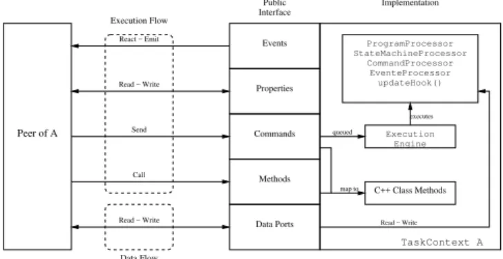
Each component model inherits a public interface from the base class (TaskContext), which defines primitives for component interactions: Events, Methods, Commands, Properties and Data Port, as seen in Figure 1.
Syn-Data Ports
TaskContext A
updateHook()
Execution Engine EventeProcessor CommandProcessor StateMachineProcessor
ProgramProcessor
Peer of A
Execution Flow
Read − Write React − Emit
Send
Call
Read − Write
Data Flow
Interface Public
Events
Properties
Commands
Methods
Implementation
queued
map to
Read − Write
C++ Class Methods
executes
Figure 1: OROCOS component interface.
chronous functions are executed as a part of the Event trig-gering procedure and hence execute in the same thread that triggered the Event. Asynchronous functions are deferred to be executed as a part of the component activity.
Methods are similar to C++ member functions, but can also be called from scripts. They are executed in a synchronous fashion with respect to the calling component, executing as an usual C++ function.
Commands are similar to Methods, but Commands are sent from a component and executed according to the activity of the receiving component, asynchronously with respect to the sender. Commands are queued for execution in the receiving component. Figure 2 explains the difference between Com-mands and Methods, supposing the interaction between two components with periodic activity with same period. When A calls a Method of B, it is executed immediately. When A sends a Command to B, the execution is deferred until the scheduling of B.
t runs
to B
Command of B runs
A B A B A B
Method of B A calls a Method
of B A sends a Command
Figure 2: Commands×Methods.
Properties are variables that can be read from a configura-tion file in Extensible Markup Language (XML) format and therefore can be used to store persistent values such as con-figuration parameters of components or data that should per-sist across shutdown and power-up of the system.
In order to use the above primitives, a component should peer with another one. By peering, a component becomes able to access the public interface of its peer, as shown in Figure 1. Note that peering is not a symmetric relation. If a component A is peer of a component B, then A can use the public
inter-face of B, but B can not use the public interinter-face of A unless B is also a peer of A.
The Data Port is a primitive for data exchange and can be configured to use a FIFO buffer or not. Also, they can be write-only, read-only or read-write and are accessed in real-time in a thread-safe fashion. Hence, while reading a Data Port, a mutual exclusion procedure ensures that data will not change until the end of the reading operation. Data Ports can also be configured to trigger the activity of a component or to execute a function upon reception of data. Of course, to exchange data, Data Ports should be connected to each other.
TheExecutionEngineblock, shown in Figure 1, is exe-cuted according to the activity of the component and imple-ments the processing of the scripts, Commands, Events and State Machines associated to the component.
As shown above, the OROCOS framework provides many possibilities for interaction and communication among com-ponents and therefore, the user has to choose what communi-cation mechanism to use for implementing his system. Many of such mechanisms are similar and could be used to replace the others, if they were not available. However, each of the communication mechanisms is best tailored for some type of communication task. Unfortunately, OROCOS does not de-fine a policy on how to use the available mechanisms and due to the complexity of the framework, it is not easy for a new user to understand all the details of each mechanism and to decide which one is best for each communication task.
3
PROPOSED ARCHITECTURE
A typical topology for a computer-based control system is shown in Figure 3.
Sensor Reference
Controller Holder Actuator
Plant
Sampler
Figure 3: Typical topology for a sampled-data control system.
The dynamic model of a manipulator robot can be repre-sented by Fu et al. (1987):
τ=D(q)¨q+H(q,q˙) +G(q) (1)
whereqis the vector of angular joint positions,τis the vec-tor of vec-torques applied on joint,D(q)is the generalized iner-tia matrix,H(q,q˙)is the vector of centrifugal and Coriolis forces andG(q)is the vector of gravity forces.
For aN-joint robot, expression (1) can be rewritten as:
¨
whereqiis the position of jointi.
By definingx=
qT q˙T T
, the model (1) can be repre-sented in a state-space form as:
˙
x=f(x, τ) (3)
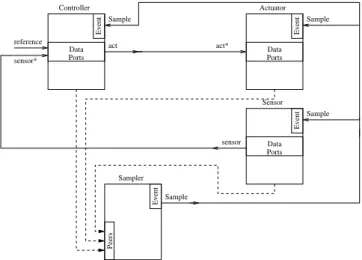
The architecture proposed in this work is based on compo-nent models for the blocks of the system shown in Figure 3 and on (3). In other words, the architecture can be used for any system with a diagram block such as Figure 3 and a model such as (3) and not only for robots. Each compo-nent model can then be instantiated in a compocompo-nent by using the specific parameters of a given robot or system. Figure 4 shows the models which are used as the base of the archi-tecture. In Section 3.2 those models are instantiated for a generic robot.
reference Data Ports Controller
Event
Sample
act sensor*
Sample
Data Ports Actuator
Event
act*
Sensor
Data Ports
Sample
Event
sensor
Peers
Sampler
Sample
Event
Figure 4: Component models of the proposed architecture.
The component models Sensor, Controller and Actuator, are models for base components and specify in-terfaces which enforce polices on how to use the services of the OROCOS framework. By using those models as bases for the components representing a specific manipulator, the user does not have to deal with the details of the communica-tion mechanisms of the framework and is free to concentrate in the details on how to specify the parameters of his specific manipulator.
TheSampleris the component that generates the sampling rate of the control loop and synchronizes the other compo-nents. It generates an Event which is received by the other components, automatically triggering a control cycle. Gener-ally, theSampleris configured to generate periodic Events, but it could be configured to generate aperiodic Events as well. Each component of the system is registered as a peer to theSamplerin order to access its events interface.
TheSensormodel abstracts the sensors of the system. it has a Data Port where it writes the values which are read from the sensors. This Data Port is based on the statexof (2) and is represented by a vector which size depends on the number of joints of the robot, given by:
sensor=
q1 q2 · · · qN q˙1 q˙2 · · · q˙N T
(4)
TheSensorcomponent model has a virtual member func-tion called sample_now(), which is called each time a Event from theSampleris received. This function should read the actual sensors of the robot and write the data on the component Data Port. By default, this function just sets a flag indicating that an Event from theSamplerwas received. Of course, given an actual robot, theSensorcomponent model would be derived in a specialized sensor component model which would overwrite thesample_now()function to ac-tually read the sensors.
TheActuatorcomponent model abstracts the system actu-ator. Similar to theSensorcomponent model it has a virtual member function calledsample_now()which is called in response to an Event from theSampler. However, its Data Port has a different behavior. It is a read-only port where the component can read the vector of actuator values from. This Data Port is based on the inputτof (2) and is represented by another vector with variable size given by:
act=
τ1 · · · τN T
(5)
Those values should be applied in each joint of the robot. Furthermore, the Data Port of this component is configured to trigger a virtual member function whenever a data is writ-ten (by an external component) to it. This behavior is sig-naled by an ∗ in the port called act∗. This virtual
func-tion is responsible for actuate the robot with the values just written to the Data Port. Again, given an actual robot, the Actuatorcomponent model would be derived in a spe-cialized actuator component model which would overwrite the virtual member functions to actually actuate the robot.
TheControllercomponent model abstracts the system controller. It has three Data Ports, similar to the signals that the controller in Figure 3 is connected to. Thereference and sensor∗ Data Ports are used for reading the
refer-ence and sensor vectors, respectively. Note that a write to the sensor∗ Data Port triggers a call to a virtual
In a typical control system, the cycle begins with a read of sensor and then, this measure is used to compute the con-trol value which is applied in the actuator. The architec-ture follows the same principle. TheSampleEvent just en-ables theControllerandActuatorand does not cause any activity, these components will be activated by their re-spectively Data Ports: sensor∗ andact∗. However, the SampleEvent enablesSensorand should then writes the sensor measurements to thesensorData Port. This write will activate theControllerwhich will generate theact and will activate theActuator.
3.1
The
Joint
Component Model
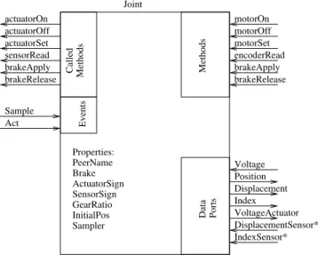
In order to represent each joint of a robot there is aJoint component model. AJointcomponent should be associ-ated with another component representing the hardware of the joint. Hence, theJointcomponent model does not rep-resent the hardware of the joint, but just the joint itself. This way, the concept of a joint of the manipulator is kept inde-pendent of the supporting hardware, thus enabling all joints to have a common interface even if their hardware is not the same. Figure 5 shows the interface of this component model.
brakeApply motorSet motorOn
brakeRelease encoderRead motorOff
brakeApply brakeRelease
Properties: PeerName Brake ActuatorSign SensorSign GearRatio InitialPos Sampler
Data Ports
Index Position Voltage
Displacement Sample
Act
VoltageActuator sensorRead
actuatorSet actuatorOff actuatorOn
Methods
Joint
Called Methods
Events
IndexSensor* DisplacementSensor*
Figure 5: TheJointcomponent model.
When aJointcomponent is created, it should be connected to a component which represents the hardware of the joint. The component which represents the hardware should pro-vide the following Methods:
actuatorOn: turn the joint actuator on
actuatorOff: turn the joint actuator off
actuatorSet: apply value to the joint
sensorRead: read the sensors of the joint
brakeApply: apply the brakes to the joint
brakeRelease: release the brakes.
EachJointcomponent has the following Properties, which describe the hardware of the joint.
PeerName: Name of the component which implements the hardware access.
Brake: Indicates whether the joint has a brake.
ActuatorSign: Used to compensate for wiring differ-ence on the joint hardware, such that when an positive value is applied, the joint moves in the positive direc-tion.
SensorSign: Similar to ActuatorSign, but used to compensate for sensor wiring, such that a positive value is read when the joint moves in the positive direction.
GearRatio: Ratio between the joint motion and the sensor readings.
InitialPos: Initial position of the joint.
Sampler: Indicate whether theJointcomponent should try to connect to theSampleandActEvents.
The Joint component model exports methods which are similar to the ones it imports from a peer specified by the PeerName Property. This way, it is possible to com-mand the joint of the robot without to comcom-mand the hard-ware directly. The motorOn and motorOff Methods are directly mapped on the imported actuatorOn and actuatorOff Methods. The same occur with the meth-ods used to handle the brakes. However, they are only exported if the Brake Property confirms that the specific joint has a brake. ThemotorSetMethod is mapped onto theactuatorSetMethod by compensating for the wiring according to the ActuatorSign Property. Finally, the sensorReadMethod returns the displacement of the joint of the robot, compensating for the wiring according to the SensorSignProperty and the reduction between the joint axis and the sensor axis by using theGearRatioProperty.
Note that a write to this Data Port should be mapped to a call to theactuatorSetMethod of the hardware component.
TheDisplacementSensor∗ Data Port receives the
dis-placement of the motor axis from the component specified by thePeerNameProperty. A write to this port triggers an event which computes the displacement of the joint, by using theGearRatioandSensorSignProperties and updates it by writing to theDisplacement Data Port. The dis-placement of the joint is also integrated with the initial con-dition given by theInitialPosProperty and updated by writing to thePositionData Port. In a similar way, the value in theIndexSensor∗ Data Port received from the
component specified by thePeerNameProperty is used to update the value made available at theIndexData Port. The sensorReadMethod imported from the component spec-ified by thePeerName Property should cause the update of IndexSensor∗ and DisplacementSensor∗ Data
Ports.
The Sample Event triggers a call to the sensorRead Method, which updates theDisplacement,Position and Index Data Ports. The Act Event triggers a read from the Voltage Data Port and a write to the VoltageActuatorData Port. These Events enables the synchronized and parallel reading and actuation of all joints.
3.2
Connecting the Base Components
Since theJointcomponent model represents a single joint of the robot and the interfaces ofSensorandActuator components are based on vectors of variables for the whole robot, there is a need for multiplexing the signals from the
N Joints of the robot to form the vector required by the Sensor. In a similar way, there is need for demultiplex-ing the vector at the output of the Actuatorto form the actuation signal to be applied to each one of theJoints.
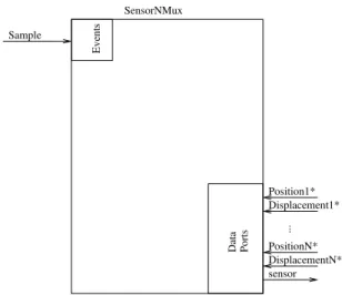
The SensorNMux component model (see Figure 6), ex-tended fromSensorcomponent, multiplexes the2N Data Ports to form a vector as given by (4). Hence, the SensorNMux component has N Data Ports for position (Position1∗, ...,PositionN∗) andNData Ports for
dis-placement (Displacement1∗, ..., DisplacementN∗).
Again, the∗is used to indicate that a write to those Data Ports
triggers an Event which stores the written value. After all2N
Data Ports have been written to following aSampleEvent, the sensor Data Port is updated with the corresponding vector.
TheActuatorNDemuxcomponent model (see Figure 7), extended from Actuator component, demultiplexes the act vector, given by (5), and writes the values to the N
Voltage1, ...,VoltageNData Ports. Then, if aSample
Data Ports
Events
Sample
sensor SensorNMux
Position1* Displacement1*
...
PositionN* DisplacementN*
Figure 6:SensorNMuxcomponent model
Event has occurred since the lastActEvent, a newActis generated. This event should force all actuators to drive the hardware at the same time.
Data Ports
Events
Sample
ActuatorNDemux
Events
Act
Voltage1
...
VoltageN
act*
Figure 7:ActuatorNDemuxcomponent model.
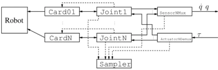
The SensorNMux and ActuatorNDemux are generic component models to multiplex and demultiplex data from sensors and actuators, respectively. In the proposed archi-tecture they are connected to withN Jointcomponents as shown in Figure 8. CardNis the component which imple-ments the actual access to the hardware of the robot. The dashed lines indicate the peering of the components, while the solid lines indicate the data flow through the Data Ports.
ex-Card01
CardN
Joint1
JointN
SensorNMux
ActuatorNDemux
Sampler
.. .
.. . ..
. ..
.
. . .
τ
˙
q q
Robot
Figure 8:Actuator,SensorandJointconnections.
tensible to other types of actuators (hydraulic, pneumatic) as long as they can be interfaced with a computer.
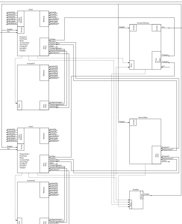
An instantiation of the models for a robot with two joints is shown in Figure 9. The following components are in-stantiated from the corresponding component models de-fined above: Card01, Card02, Joint1, Joint2, Sensor2Mux, Actuator2DemuxandSampler. Note that the controller is not included yet.
The sensor read/actuator write cycle can be described as fol-lows:
1. TheSampleEvent is generated and theSensor2Mux andActuator2Demuxcomponents will start to wait for something to be written in their Data Ports: DisplacementX∗ and Act∗ respectively. At the
same time, the Joint1 and Joint2 components will receive the same Event and will call their own encoderReadMethods.
2. Each Card component will execute the encoderRead Method which will write the ap-propriate displacement and index status into the Data Ports of eachJointcomponent. This will cause the update of Position, Displacement andIndex Data Ports, as explained in Section 3.1, which are connected to Data Ports ofSensor2Muxcomponent.
3. After all DisplacementX∗ Data Ports of Sensor2Mux are updated, the sensor is writ-ten to and the sensor read cycle is done.
4. At other side, when a data is written to the Act∗
Data Port of Actuator2Demux, the Voltage1 and Voltage2 Data Ports, which are connected to VoltageData Ports ofJointXcomponents, are up-dated and theAct∗Event is generated.
5. Again, theJointXcomponents catch this Event and call their ownmotorSetMethods, which actually ac-tuate its joint, concluding the actuator write cycle.
3.3
An Independent PID for Each Joint
Similar to theSensorandActuatorcomponent models in Figure 4, theControllercomponent model should be extended to implement the desired control law. In this sec-tion, theControllercomponent model is extended to im-plement an independent PID controller for each joint of the robot. This scheme treats each joint of the robot as a simple joint servomechanism, thus neglecting the coupling among joints.
To implement this control strategy, at first, a generic PID component model will be implemented. This component model can be instantiated with appropriate gains for each joint of the robot. Then, theControllerwill be extended to interact with theNPIDcomponents.
3.3.1 Component Model for aPIDController
A PID controller with saturation has three gains: the pro-portional gainKp, the integral gainKi and the differential gainKd. The saturation is represented by the values uand
u, meaning the minimum and maximum value for the con-troller output. In discrete time form, the PID can be written as (Astrom and Wittenmark, 1984):
u[k] =u[k−1] +kp(e[k]−e[k−1]) +kie[k] +kd(e[k]−2e[k−1]
+e[k−2]) , u≤u[k]≤u
u[k] =u , u[k]> u
u[k] =u , u[k]< u
(6) wheree[k]is is the difference between the reference and the output value.
Figure 10 shows the interface of the PID component model. Note that, by defining the PID parameters as Properties, dif-ferent PID components can be instantiated from the same model. The component is activated when a value is write to itsSen∗Data Port. Then, the error valuee[k]is computed
as difference betweenRefandSen∗Data Ports, and by
us-ing (6), uis computed and written into theOutData Port. In the end, the values ofe[k−2]ande[k−1]are updated toe[k−1]ande[k], and the component will be waiting for another write to itsSen∗Data Port.
3.3.2 ControllerNPIDComponent Model
Portas de Dados
brakeApply motorSet motorOn
brakeRelease encoderRead motorOff
brakeApply motorSet motorOn
brakeRelease encoderRead motorOff
brakeApply brakeRelease brakeApply brakeRelease
Propriedades: PeerName Brake ActuatorSign SensorSign GearRatio InitialPos Sampler Properties PeerName Brake ActuatorSign SensorSign GearRatio InitialPos
Sampler Data Ports
Peers
Data Ports
Peers
Sampler
Sample
Event
Peers
Data Ports
Peers
Events
Sample Sample
sensor Index
Position Voltage
Displacement Sample
Act
brakeApply brakeRelease
Index Position Voltage
Displacement Sample
Act
brakeApply brakeRelease actuatorOn
actuatorOff actuatorSet sensorRead
VoltageActuator
actuatorOn actuatorOff actuatorSet sensorRead
DisplacementSensor IndexSensor
actuatorOn actuatorOff actuatorSet sensorRead
VoltageActuator
actuatorOn actuatorOff actuatorSet sensorRead
DisplacementSensor IndexSensor Joint1
Methods
Actuator01
Methods
Data Ports
Joint2
Methods
Actuator02
Data
Methods
Ports
Sensor2Mux Actuator2Demux
Events
Called Methods
Events
Called Methods
Events
Events
Act
Voltage1
Voltage2
act*
Position1* Displacement1*
Position2* Displacement2*
VoltageActuator* DisplacementSensor* IndexSensor* VoltageActuator* DisplacementSensor* IndexSensor*
Ref Out PID
Properties:
Data Ports
Sen*
kp
ki
kd
u u
Figure 10:PIDcomponent model.
Data Ports
Events
Sample
ControllerNPID
reference act Sen1 Ref1 Out1*
...
SenN RefN OutN* sensor*
Figure 11:ControllerNPIDcomponent model.
This component model has Data Ports to communicate with
N PIDcomponents. It demultiplexes thereferenceand sensorvectors and write the values to the2N Data Ports (Ref1,...RefN) and (Sen1,...SenN). Also, it acts as a mul-tiplexer, by collecting the outputs of theNPIDcomponents written to theOut1,...OutNData Ports, and writing them as a vector to theactData Port after aSampleEvent. The block diagram of this extension is shown in Figure 12.
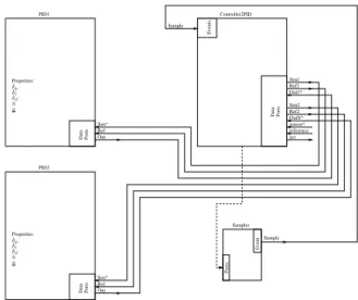
Figure 13 shows the connections for a system with two PID controllers. The control cycle of Figure 13 can be described as follows:
1. The Sample Event is generated and the Controller2PID component starts to wait for something to be written to itssensor∗Data Port.
PID01 PIDN
ControllerNPID
Sampler
. . .
τ
˙
q q
¨ qd q˙d qd
Figure 12: Block diagram of the ControllerNPID exten-sion.
Sampler Sample
Event
Peers
Data Ports
Events
Sample
Ports
Ref Out
Ref Out
Sen2 Ref2 PID1
Data
Properties:
PID2
Properties:
DataPorts
Controller2PID
Sen1 Ref1 Out1*
reference act sensor* OutN*
Sen* Sen*
kp kp
k i ki
kd kd
¯
u
¯
u
u u
Figure 13: Complete system for a two joint robot with inde-pendent PID controllers.
2. When a write to sensor∗ occurs, the Controller2PID reads its reference and sensor∗ Data Ports, demultiplexes its into Ref1, Ref2, Sen1and Sen2. Then, it waits for all of its OutX∗Data Ports to be updated.
3. Each PID component react to the write of eachSen∗
and update eachOutData Port.
3.4
PID with Feedforward Compensation
An independent PID for each joint strategy may work at low speeds, but generally present a poor performance. These problems arise because the coupling among joints and grav-ity forces are neglected. Better results can be achieved by explicit exploring the knowledge about the dynamic model of the robot.
In this section the Controllercomponent model is ex-tended to implement a PID control with feedforward com-pensation, similar to the PD with feedforward compensation presented in Craig (1989). However, here an integral term is included to reduce steady-state and modeling errors. This control strategy is represented by the block diagram shown in Figure 14. This strategy consists of a PID feedback plus a feedforward computation of the the nominal robot dynam-ics (1) along the desired joint position trajectory.
PID +
+
Robot
Model +
−
output reference
¨ qdqd˙ qd
˙ q q
ud
δu u
Figure 14: Controller with feedforward compensation.
It is convenient to rewrite the robot model (1) as:
˙
x(t) =f(x(t), u(t)) (7)
If the desired statesxd(t)are known along the desired trajec-tory, then the torqueud(t), are also known, can be computed by (1) and satisfy:
˙
xd(t) =fa(xd(t), ud(t)) (8)
wherefais the robot model.
The result of (7) minus (8) is
δx˙(t) =h(δx(t), δu(t)) (9)
where δx(t) = x(t)−xd(t), δu(t) = u(t)−ud(t) and
h(·,·)represents the difference between the robotf(·,·)and the robot modelfa(·,·).
If the state x(t) is close to desired statexd(t), then a PID control law, as defined by (6), can be used to makeδx(t) converge towards zero.
3.4.1 The RobotModelComponent
This component implements the inverse model of the robot (1). Given the position, velocity and acceleration of the
joints it computes the desired torque of the robot. This com-ponent model is shown in Figure 15 and its internal work-ing is similar to thePIDcomponent model, however it com-putes (1) instead of (6). The Data PortIn∗receives a
vec-tor with the desired position, velocity and acceleration of the robot and computes, by using (1), the torque, which is written to theOutData Port.
Out Model
Data Ports
In*
Figure 15: RobotModelcomponent.
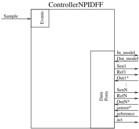
3.4.2 ControllerNPIDFFComponent Model
The ControllerNPIDFF extends the Controller component model to implement a PID with feedforward compensation. Therefore, in order to implement the PID con-troller with feedforward compensation it is only necessary to change the component model thatControlleris instan-tiated from toControllerNPIDFF. Figure 16 shows the interface of theControllerNPIDFFcomponent model.
Data Ports
Events
Sample
...
In_model Out_model*
Sen1 Ref1 Out1*
SenN RefN OutN*
reference act sensor*
ControllerNPIDFF
The implementation is similar to the ControllerNPID component model. It writes a vector with the robot position, velocity and acceleration to theIn_modelData Port, which triggers the robotModelcomponent to compute the robot torque, which is received by the ControllerNPIDFF through theOut_model∗ Data Port. Then it writes the N
values ofsensorto itsSenXData Ports, which triggers the PIDcomponent. In the end, the torque values are them added to the values received from thePIDof each joint through the OutN∗ Data Port and written to the ActData Port, to be
used by the system actuators.
4
EXPERIMENTAL RESULTS
The architecture presented in Section 3 was implemented in the vision system of Janus robot. It consists of two links connected in series by two rotational joints. Two cameras are attached to the far-end of the chain. Each joint is driven by a DC motor and has an incremental quadrature encoder and a reference index inductive sensor.
Figure 17: The vision system of Janus.
Each joint also has an actuator card which uses a CANbus with1Mbit/s for real-time data transfer to a host PC. More details about the hardware and software for this card can be found in Santini and Lages (2008). This card, named as AIC, is modeled as a component which has an interface compat-ible with the one defined byJointcomponent model, as shown in Section 3.1.
4.1
Independent PID for Each Joint
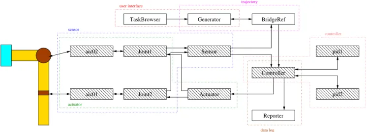
Figure 18 shows the block diagram for an independent PID controller for each joint. Each component of Figure 18 is in-stantiated from a component model as shown in Table 1 and all peering and Data Port connection as shown in Figures 9 and 13 are performed. The hatched components have their execution in real-time and the arrows represent the informa-tion flow between components.
Table 1: Characteristics of system.
Component Model Activity Priority Period
Sampler Sampler PeriodicActivity 1 10ms
aic01 AIC SequentialActivity — —
aic02 AIC SequentialActivity — —
Joint1 Joint SequentialActivity — —
Joint2 Joint SequentialActivity — —
Sensor Sensor2Mux NonPeriodicActivity 2 —
BridgeRef BridgeRef NonPeriodicActivity 97 —
Generator nAxisGenPos PeriodicActivity 98 10ms
Controller Controller2PID NonPeriodicActivity 3 —
pid1 PID SequentialActivity — —
pid2 PID SequentialActivity — —
Actuator Actuator2Demux NonPeriodicActivity 3 —
Reporter FileReporting PeriodicActivity 100 10ms
TaskBrowser TaskBrowser NonPeriodicActivity 255 —
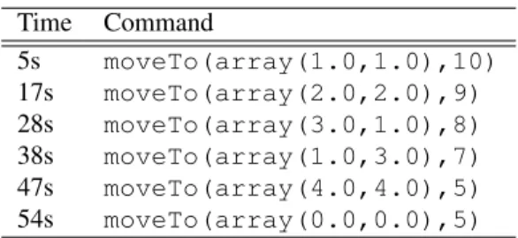
In order to test the proposed architecture, a sequence of com-mands, given by Table 2, is executed. Each command is sent at its respective time. The desired and measured position for each joint, are shown in Figure 19.
Table 2: Sequence of test commands.
Time Command
5s moveTo(array(1.0,1.0),10)
17s moveTo(array(2.0,2.0),9) 28s moveTo(array(3.0,1.0),8) 38s moveTo(array(1.0,3.0),7) 47s moveTo(array(4.0,4.0),5) 54s moveTo(array(0.0,0.0),5)
To evaluate the computing performance of the proposed ar-chitecture, the activity of each component in a full control cy-cle is measured. The Figure 20 shows the timeline of actions started by theSampleEvent. As can be seen, the computing of the control loop takes less than 1ms, which is adequate for most robots.
Att0= 0, theSampleEvent is generated bySamplerand
the components which are connected to this Event are called in a synchronous way. Figures 9 and 13 shows thatJoint1, Joint2,Sensor,ControllerandActuatorare con-nected toSampleEvent.
First, the Joint1 executes and calls the SensorRead Method from aic1card. This process takes about259 µs
which is the time of sensing the system using the AIC cards through CANBus. Then, at f1, the Displacement and
PositionData Ports ofJoint1are updated.
After that, the process is done again for the second joint un-til f2. SoSensor,ControllerandActuatorenable
their respective Data Ports: Position1∗, Position2∗, Displacement1∗, Displacement2∗, sensor∗ and act∗.
com-BridgeRef TaskBrowser Generator
Reporter
✁✁✁✁✁✁✁✁ ✁✁✁✁✁✁✁✁
✂✁✂✁✂✁✂✁✂✁✂✁✂✁✂✁✂ ✂✁✂✁✂✁✂✁✂✁✂✁✂✁✂✁✂
✄✁✄✁✄✁✄✁✄✁✄✁✄✁✄✁✄ ✄✁✄✁✄✁✄✁✄✁✄✁✄✁✄✁✄ ✄✁✄✁✄✁✄✁✄✁✄✁✄✁✄✁✄
☎✁☎✁☎✁☎✁☎✁☎✁☎✁☎✁☎ ☎✁☎✁☎✁☎✁☎✁☎✁☎✁☎✁☎ ☎✁☎✁☎✁☎✁☎✁☎✁☎✁☎✁☎
✆✁✆✁✆✁✆✁✆✁✆✁✆✁✆ ✆✁✆✁✆✁✆✁✆✁✆✁✆✁✆
✝✁✝✁✝✁✝✁✝✁✝✁✝✁✝ ✝✁✝✁✝✁✝✁✝✁✝✁✝✁✝
✞✁✞✁✞✁✞✁✞✁✞✁✞✁✞ ✞✁✞✁✞✁✞✁✞✁✞✁✞✁✞ ✞✁✞✁✞✁✞✁✞✁✞✁✞✁✞
✟✁✟✁✟✁✟✁✟✁✟✁✟✁✟ ✟✁✟✁✟✁✟✁✟✁✟✁✟✁✟ ✟✁✟✁✟✁✟✁✟✁✟✁✟✁✟
✠✁✠✁✠✁✠✁✠✁✠✁✠✁✠ ✠✁✠✁✠✁✠✁✠✁✠✁✠✁✠
✡✁✡✁✡✁✡✁✡✁✡✁✡✁✡ ✡✁✡✁✡✁✡✁✡✁✡✁✡✁✡
☛✁☛✁☛✁☛✁☛✁☛✁☛✁☛ ☛✁☛✁☛✁☛✁☛✁☛✁☛✁☛ ☛✁☛✁☛✁☛✁☛✁☛✁☛✁☛
☞✁☞✁☞✁☞✁☞✁☞✁☞✁☞ ☞✁☞✁☞✁☞✁☞✁☞✁☞✁☞ ☞✁☞✁☞✁☞✁☞✁☞✁☞✁☞
✌✁✌✁✌✁✌✁✌✁✌✁✌✁✌ ✌✁✌✁✌✁✌✁✌✁✌✁✌✁✌ ✌✁✌✁✌✁✌✁✌✁✌✁✌✁✌
✍✁✍✁✍✁✍✁✍✁✍✁✍✁✍ ✍✁✍✁✍✁✍✁✍✁✍✁✍✁✍ ✍✁✍✁✍✁✍✁✍✁✍✁✍✁✍
✎✁✎✁✎✁✎✁✎✁✎✁✎✁✎ ✎✁✎✁✎✁✎✁✎✁✎✁✎✁✎
✏✁✏✁✏✁✏✁✏✁✏✁✏✁✏ ✏✁✏✁✏✁✏✁✏✁✏✁✏✁✏
✑✁✑✁✑✁✑✁✑✁✑✁✑✁✑ ✑✁✑✁✑✁✑✁✑✁✑✁✑✁✑ ✑✁✑✁✑✁✑✁✑✁✑✁✑✁✑
✒✁✒✁✒✁✒✁✒✁✒✁✒✁✒ ✒✁✒✁✒✁✒✁✒✁✒✁✒✁✒ ✒✁✒✁✒✁✒✁✒✁✒✁✒✁✒ sensor
aic02
aic01 Joint2
Joint1 Sensor
Actuator
Controller
pid2 pid1
controller trajectory
user interface
data log
actuator
Figure 18: Block diagram for an independent PID for each joint.
ponent is activated and joinsPosition1∗,Position2∗, Displacement1∗, Displacement2∗ into sensor
Data Port. This process takes about 20µs and is done at
f4whenControlleris activated.
Untilf5, theControllersplits the data in thesensor∗
Data Port in position and displacement of each joint, interacts with twoPIDcomponents and writes theactData Port to theActuator. This is done in approximately30µs.
Then, theActuatoris activated and splits theact∗ into
theVoltage1andVoltage2Data Ports which are con-nected toJoint1andJoint2. In the end, theActuator emits theActEvent att5taking approximately10µs.
The Act Event activates Joint1 and Joint2 to effec-tively actuate over each joint of robot. This takes about 150 µs. Note that the aic01 cards takes less time than aic02 by hardware issues. After f6, all the real-time
component have executed and the other components like, GeneratorandReportercan execute.
Note that, by using the proposed architecture, the control cy-cle is performed in724µsfor two joints, which means about 362µsfor each joint. In (Santini and Lages, 2008) a similar controller was implemented by using a monolithic structure, with a single loop that reads the sensor, computes the control law and drives the actuator. The control loop was performed in331µsfor a single joint. Hence, the proposed architec-ture imposes a small overhead on the system. However, to be adapted to another robot, the monolithic implementation requires a rewrite of the program source code, while the ar-chitecture proposed here requires just the setting of the joint parameters on its configuration files. There is no need to change the program source code, with the associated com-plexity and the possibility of introduction of bugs.
4.2
PID with Feedforward Compensation
In order to implement the PID controller with Feedforward Compensation, just a minor change is needed on the basic in-dependent PID controller for each joint. It is only necessary to change the instantiation of theControllercomponent fromControllerNPIDtoControllerNPIDFF. Since ControllerNPIDFFuses the model of the robot, as de-tailed in section 3.4.2, two more components are added to the system, as shown in Table 3.
Table 3: Characteristics of the new components for the PID controller with feedforward compensation.
Component Model Activity Priority Period
Controller ControllerNPIDFF NonPeriodicActivity 3 —
0 10 20 30 40 50 60 70 0
0.5 1 1.5 2 2.5 3 3.5 4
Measured Desired
P
o
sitio
n
(ra
d
)
Time (s)
(a) Joint 1.
0 10 20 30 40 50 60 70
−1 −0.5 0 0.5 1 1.5 2 2.5 3 3.5
Measured Desired
P
o
sitio
n
(ra
d
)
Time (s)
(b) Joint 2.
Figure 19: Position with PID controller.
Joint1
aic01
Joint2
Sampler aic02
Sensor
Actuator pid1
pid2
t 0
Others
Controller
t1 t2 t3 t4t5 t6
f1 f2 f3f4 f5 f6
t1= 259µs
t2= 517µs
t3= 535µs
t4= 566µs
t5= 574µs
t6= 724µs
Figure 20: Timeline of action during a control cycle.
0 10 20 30 40 50 60 70
−0.08 −0.06 −0.04 −0.02 0 0.02 0.04 0.06 0.08
PID
PID with feedforward
E
rro
r
(ra
d
)
Time (s)
(a) Joint 1.
0 10 20 30 40 50 60 70
−0.12 −0.1 −0.08 −0.06 −0.04 −0.02 0 0.02 0.04 0.06
PID
PID with feedforward
E
rro
r
(ra
d
)
Time (s)
(b) Joint 2.
Figure 21: Position error.
Regarding the timing of the control loop computation, there is a10µsincrease in the computing time, due to the need to compute the robot model. However, a monolithic im-plementation is subject to the same increase in comput-ing time. In this particular case, that happens because the model component has a SequentialActivity, which means that it executes in the context of its caller (the ControllerNPIDFF), just like a function call in a mono-lithic implementation.
5
CONCLUSION
This paper presented an architecture for control of manipu-lator robots based on components. The approach is modular and enables the reuse of components developed earlier, thus shortening the development time and enabling the replace-ment of system components without the need to understand the whole system. Furthermore, the proposed architecture defines some polices on the use of the resources available from the OROCOS framework, therefore making it easier for beginners to start to use the system.
The flexibility of the architecture was demonstrated by im-plementing two control strategies with minor changes: In-dependent PID controllers and a controller with feedforward compensation. The architecture is also independent of robot and can be easily extended to other systems.
The measured times show that the architecture does not in-troduce significant computing time in the control loop. This allows for the use of the proposed architecture in real-time.
REFERENCES
Astrom, K. J. and Wittenmark, B. (1984). Computer Con-trolled Systems: Theory and Design, Prentice Hall Pro-fessional Technical Reference, Indianapolis.
Barrett (2010). Barrett technology, inc. Avail-able: <http://www.barrett.com/robot/ products-arm.htm>.
Brugali, D. and Scandurra, P. (2009). Component-based robotic engineering (part i) [tutorial], Robotics & Au-tomation Magazine, IEEE16(4): 84–96.
Bruyninckx, H. (2001). Open robot control software: the orocos project,Proceedings of the IEEE International Conference on Robotics and Automation, Vol. 3, Piscat-away: IEEE Press, Seoul, pp. 2523–2528.
Craig, J. J. (1989). Introduction to Robotics Mechanics and Control, second edn, Addison-Wesley.
Ford, W. (1994). What is an open architecture robot con-troller?,Proceedings of the IEEE International
Sympo-sium on Intelligent Control, Piscataway: IEEE Press, Columbus, pp. 27–32.
Fu, K. S., Gonzales, R. C. and Lee, C. S. G. (1987).Robotics Control, Sensing, Vision and Intelligence, Industrial Engineering Series, McGraw-Hill, New York.
Gaspar, M. D. (2003). Uma biblioteca configurável para controle tempo real de robôs manipuladores, Dis-sertação (mestrado), Universidade Federal de Minas Gerais, Belo Horizonte.
Kozlowski, K. (1998). Modelling and Identification in Robotics, Springer-Verlag New York, Inc., Secaucus, NJ, USA.
Liandong, P. and Xinhan, H. (2004). Implementation of a pc-based robot controller with open architecture, Proceed-ings of the IEEE International Conference on Robotics and Biomimetics, Piscataway: IEEE Press, Shenyang, pp. 790–794.
Lloyd, J. E. (1992). RCI reference manual, Technical re-port, McGill Research Centre for intelligent Machines, McGill University, Montréal.
Microsoft (2008). Robotics developer studio. Available: <http://www.microsoft.com/robotics>.
Neuronics (2010). Neuronics AG - linux robot. Avail-able: <http://www.neuronics.ch/cms_de/ web/index.php?id=364>.
Object Management Group (2010). The corba website. Available:<http://www.corba.org/>.
ROS.org (2010). ROS. Available: <http://www.ros. org>.
Santini, D. C. and Lages, W. F. (2008). A distributed robot control architecture using RTAI, Proccedings of the Tenth Real-Time Linux Workshop, Centro Universitario del Norte, Universidad de Guadalajara, Colotlán, Mex-ico, pp. 1–5.
Smith, C. and Christensen, H. I. (2009). Constructing a high performance robot from commercially available parts,
Robotics and Automation Magazine16: 75–83.
Swevers, J., Verdonck, W. and De Schutter, J. (2007). Dy-namic model identification for industrial robots, Con-trol Systems Magazine27(5): 58–71.