Photoelastic analysis of stress generated by
Connecticut Intrusion Arch (CIA)
Alessandro Schwertner1, Renato Rodrigues de Almeida2, Alcides Gonini Jr3, Marcio Rodrigues de Almeida3
1 Universidad Católica Nuestra Señora de la Asunción (UCA), Department of
Orthodontics, Hernandarias, Paraguai-PY.
2 Universidade de São Paulo (USP), Bauru Dental School, Department
of Orthodontics (Bauru/SP, Brazil) and Universidade Norte do Paraná (UNOPAR), Department of Orthodontics (Londrina/PR, Brazil). 3 Universidade Norte do Paraná (UNOPAR), Department of Dental Materials
and Orthodontics (Londrina/PR, Brazil).
Submitted: April 26, 2016 - Revised and accepted: October 14, 2016
Objective: The present in vitro study evaluated, by means of the photoelastic technique, the effects generated by the Connecticut Intrusion Arch (CIA), with a 90o bend on the distal surface of molar tubes and using the 4 x 2 appliance on the anterior and
pos-terior regions of the upper dental arch. Methods: Five models were manufactured, in which two different clinical situations were correlated: 1) use of intrusion arch not cinched back and transpalatal bar for anchorage (Group 1); 2) use of intrusion arch cinched back and transpalatal bar for anchorage (Group 2). Stress generated in the apical and middle regions of tooth roots of maxillary anterior teeth and maxillary first molars was evaluated. Results: Taking a reference value of 1.0 MPa = 100%, qualitative descrip-tive analysis was performed, which showed uniformity between stress values in the apical region of anterior teeth of both groups (G1 and G2). In the posterior region, for models with the arch cinched back (G2), stress remained within 100%. As for G1 models (with the arch not cinched back), variations in the mesial surface of first molars were observed, with an increase of 20% in the generated stress. The apical region did not undergo any changes, while in the distal region of molars there was a decrease of 20% in stress. Conclusion: Laboratory results revealed differences in stress between Groups 1 and 2 in the molar region, thereby indi-cating that there was a tendency towards mesial root tipping of first molars when the distal end of the CIA was not cinched back.
Keywords: Intrusion arch. Photoelasticity. Physical properties.
DOI: http://dx.doi.org/10.1590/2177-6709.22.1.057-064.oar
How to cite this article: Schwertner A, Almeida RR, Gonini Jr A, Al-meida MR. Photoelastic analysis of stress generated by Connecticut Intrusion Arch (CIA). Dental Press J Orthod. 2017 Jan-Feb;22(1):57-64.
DOI: http://dx.doi.org/10.1590/2177-6709.22.1.057-064.oar
» The authors report no commercial, proprietary or financial interest in the products or companies described in this article.
Contact address: Marcio Rodrigues de Almeida
Via Galileu, 1-15, Bauru, São Paulo, Brazil - ZIP: 17053-093 E-mail: [email protected]
Objetivo: o presente estudo in vitro avaliou, por meio da técnica de fotoelasticidade, os efeitos produzidos pelo Arco de Intrusão de Connecticut (CIA) com dobra de 90o na face distal dos tubos molares e usando um aparelho 4 x 2 nas regiões anterior e posterior da
arcada dentária superior. Métodos: foram confeccionados cinco modelos, aos quais foram correlacionadas duas situações clínicas diferentes: 1) uso do arco de intrusão sem dobra distal, mas com barra transpalatina para ancoragem (G1); 2) uso do arco de intru-são com dobra distal e barra transpalatina para ancoragem (G2). Avaliou-se as tensões geradas nos terços apical e médio das raízes dos dentes anterossuperiores e primeiros molares superiores. Resultados: considerando-se um valor de referência de 1,0 MPa = 100%, foi realizada uma análise descritiva qualitativa, a qual demonstrou uniformidade entre os valores de tensão na região apical dos dentes anteriores nos dois grupos (G1 e G2). Na região posterior dos modelos com arcos com dobra distal (G2), a tensão foi mantida em 100%. Já nos modelos do G1 (arco sem dobra distal), foram observadas variações na face mesial dos primeiros mola-res, com um aumento de 20% na tensão gerada. A região apical não sofreu qualquer alteração, ao passo que, na região distal dos molares, houve uma diminuição de 20% na tensão. Conclusão: os resultados laboratoriais revelaram diferenças, entre os grupos 1 e 2, para a tensão gerada na região dos molares, indicando que houve uma tendência de mesialização da raiz dos primeiros molares quando não foi realizada a dobra na extremidade distal do CIA.
INTRODUCTION
The 4 x 2 appliance is considered a versatile appli-ance, with easy adaptability and high tolerance for orth-odontic treatment in the mixed dentition. In addition to being used for alignment and leveling of maxillary and mandibular incisors, it is used for retraction of incisors in cases of Class II, Division 1 malocclusion, upright-ing of incisors in cases of Class II, Division 2 malocclu-sion, and for minimizing diastemas while gaining space for permanent canines. Also, it assists on correcting the overbite associated with distalization of irst molars dur-ing application of intrusive mechanics.1,2 Overbite cor-rection is one of the greatest challenges faced by orth-odontic treatment.3 Depending on diagnosis and treat-ment goals, overbite can be treated with intrusion of mandibular and/or maxillary incisors, extrusion of the posterior segment, or a combination of both.4,5
Some of the previous studies on intrusive mechanics have compared diferent methods for overbite correc-tion,6,7 with a few studies employing in vitro8 conditions and/or with animals.9 One of the methods employed to this end is the utility arch, or a two-couple intrusion arch, which exerts greater moment in the anterior re-gion (counterclockwise intrusive moment) when used in the upper arch. This is also because the caudal angle is located on the mesial surface of the molar tube (re-sulting in an extrusive efect with a clockwise moment), thus establishing a statically determined system.10,11
Cases in which upper intrusive mechanics with a seg-mented arch is opted for, due to the extrusive force reaction component in the molar region, have a tendency to decrease inter-molar distance;10 that is, constriction of the maxilla in the posterior region, a reaction that can be avoided by means of transpalatal bar12 or high-pull headgear.5
Force exerted for intrusion of anterior teeth should be light and continuous.13,14 These characteristics are pro-moted by alloys such as titanium molybdenum (TMA), and particularly in the Connecticut Intrusion Arch (CIA), which is a nickel-titanium arch with low load-delection rates, releasing forces ranging from 35 to 45 g, distributed over the four anterior teeth. Importantly, such forces can vary when an intrusion arch is used, depending on the distance between molars and incisors.15
Assessment of stress distribution in the periodon-tium, resulting from the use of an intrusion arch, may be carried out by photoelasticity, a laboratory method that simulates, through photoelastic fringes,
the dissipation of strength and movement generated during intrusive mechanics.8,16 The applicability of photoelasticity in orthodontic mechanics as an ex-perimental technique, anticipates potential mechani-cal response resulting from specific efforts.17 For this reason, it is a key ally to clinically understand reac-tions presented by teeth and supporting systems, re-sulting from the mechanotherapy employed.
The irst report on the use of photoelasticity in den-tistry was published in 1935, by Zak.18 He investigated orthodontic movements to assess phenomena occurring in the supporting periodontium. To analyze stress and deformation generated in transparent polymers, a po-lariscope is used.16
Photoelasticity has been widely used in Dentistry, especially in Orthodontics,16,19,20 Oral and Maxillo-facial Surgery,21 Restorative Cosmetic Dentistry,22,23 Prosthodontics,24 Periodontology25 and Implantol-ogy,26 to evaluate occlusion recovery. To this end, models with speciic photoelastic resins are manufac-tured to simulate the efects of mechanotherapy on the structures to be studied.
The applicability of photoelasticity as an experimen-tal technique to study orthodontic mechanics16 allows to anticipate the potential mechanical response, either in simulating correction of the curve of Spee, traction of im-pacted canines by means of reciprocal anchorage or canine retraction by means of loops and elastics.27 A protocol for manufacturing study models with photoelastic resin was developed for stress analysis during canine retraction using mini-implants anchorage, indicating the feasibility of veri-fying the results obtained with the photoelastic method simulating supporting structures.16
Thus, the aim of this in vitro study was to evaluate the efects of intrusive mechanics on the anterior and posterior regions of the upper dental arch by means of photoelasticity. The null hypothesis was that the use of intrusion arches with or without a 90o bend (cinched back arch) in the distal surface of maxillary irst molars does not imply diferences in stress generated in the re-gion of incisors and maxillary molars roots.
MATERIAL AND METHODS Laboratory study
re-Figure 1 - Brackets previously fixed to a steel wire segment before being pas-sively placed to teeth on the photoelastic model.
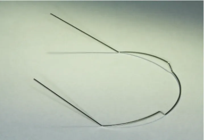
Figure 2 - Upper long 0.017 x 0.025-in Connecticut Intrusion Arch (CIA) (Or-tho Organizers, Carlsbad, CA, USA).
positioned over the impression. The set consisted of crown and root portions, thus creating replicas of natural teeth. With the teeth in place, the entire impression and the root portion of these teeth were covered with colorless, chemi-cally activated acrylic resin (Jet, Clássico Artigos Ordon-tológicos, Campo Limpo Paulista/SP, Brazil).
Ater acrylic resin was polymerized and the model was removed, the region of teeth #13 to #15 was sec-tioned vertically with a carborundum disk at low rotation speed, in order to obtain an arch section with the height of the original preserved model (2 cm). With the aid of a tungsten drill at low rotation speed, buccal and lingual walls were reduced to a minimum width (1 cm), taking the width of roots in bucco-palatal direction as reference; however, without exposing them. The resulting walls in acrylic resin were inished with sandpaper strips (#1200 grit) at low rotation speed and polished with a brush, pumice stone and water solution, followed by polishing with a felt disk and a chalk powder-water solution.
Excess polishing material was removed with water. Subsequently, the surface was dried and a standard analy-sis performed for laws. A smooth and uniform surface was obtained and no laws were identiied; therefore, a second silicone impression was obtained. This second im-pression served as reference for the pilot study and also for preparation of the ive deinitive models made with lex-ible epoxy resin and hardener (G IV, Polipox, São Paulo, SP, Brazil).8 The photoelastic G IV set was mixed in the ratio recommended by the manufacturer (100:50 ml) in a beaker and with the aid of a glass rod. Subsequently, it was stored at a temperature of 45 oC, to facilitate ma-terial homogenization. Resin was then poured into the
impressions and remained at rest for 24 hours, ater which the photoelastic models were obtained.
Considering the deinitive models, bands were placed on upper irst molars (Roth prescription/Abzil Lancer-3MTM, São José do Rio Preto, Brazil), and cemented with glass ionomer (Fuji Ortho LC, GC América Cor-poration, Tokyo, Japan). Triple tubes (Abzil Lancer-3MTM, São José do Rio Preto, Brazil) were welded to the bands. For the upper central and lateral incisors, brackets (Kirium, slot 0.022 x 0.028-in, Abzil Lancer-3MTM, São José do Rio Preto, Brazil) were bonded with Super Bonder glue (Loctite, Barueri, Brazil), ater be-ing tied to a steel 0.019 x 0.025-in arch segment with 0.008-in ligature wire, so that they could be passively attached to teeth (Fig 1).
Once the intrusion arch was positioned in each group, stress was automatically generated in the pho-toelastic model representing the alveolar bone struc-tures. The latter was taken to the front of a relection polariscope (Vishay LF/Z-2, Malern, USA) which allowed stress evaluation (Fig 6A). Stress was mea-sured at predetermined points around maxillary ante-rior and posteante-rior teeth, on both let and right sides, which had their root portion split up in the following thirds: 1 mm of the middle third and 1 mm of the api-cal third (Fig 6B). With each test, the stress generated at each point (1 to 8) was automatically analyzed by a sotware (OS CALC 2.0) which converted stress values into megapascals (MPa) (strength divided by area, being 1 MPa = 1.19 kgf/cm2) (Figs 7 and 8).
LABORATORY RESULTS Sample power
Based on the mean standard deviation obtained in both groups for the eight points (0.24 MPa), adopt-ing an alpha error of 5% and adjustadopt-ing for non-para-metric tests by means of the Asymptotic Relative Ef-iciency (ARE) — technique advocated by Randles and Wolfe28 — a sample size of n = 5 in each group pre-sented an 80% power to detect a minimum diference of 0.6 MPa among the mean values of groups.
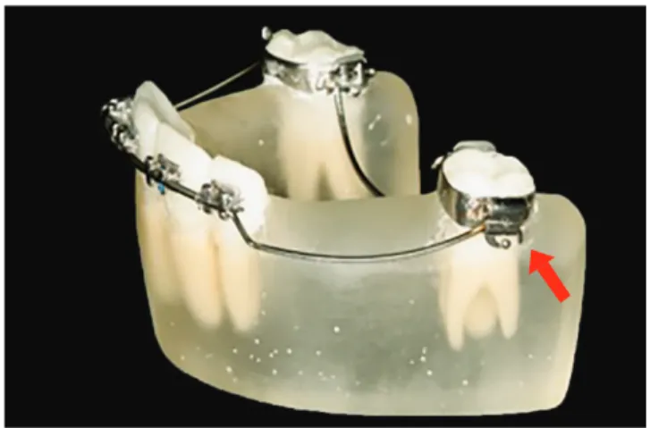
Figure 3 - G1 (with palatal bar and the arch not cinched back).
Figure 5 - Crystal model base (2 mm) for fixation and stabilization of photo-elastic models.
Figure 8 - A) Image of the anterior teeth in the polariscope: model with transpalatal bar and cinching back the intrusion arch (G2). B) Image of molars in the polariscope: model with transpalatal bar and cinching back the intrusion arch (G2).
Figure 6 - A) Reflection polariscope for analysis of stress generated in the photoelastic model. B) Analysis scheme of the middle and apical thirds, bilaterally numbered from mesial to distal.
Figure 7 - A) Image of anterior teeth in the polariscope: model with transpalatal bar and without cinching back the intrusion arch (G1). B) Image of molars in the polariscope: model with transpalatal bar, without cinching back the intrusion arch (G1).
A B
A
A
B
Figure 9 - Scheme illustrating stress generated in the posterior region of G1 group (variation of ± 20% in stress generated between points 6 and 8).
Figure 10 - Scheme illustrating stress generated in the posterior region of G2 group, showing no variation.
Model Points Tension (MPa)
without distal bend
6 1.2 (120%)
7 1.0 (100%)
8 0.8 (80%)
with distal bend
6 1.0 (100%)
7 1.0 (100%)
8 1.0 (100%)
Table 1 - Stress generated in the posterior region in the models of both groups.
Regarding photoelasticity, a qualitative descrip-tive analysis was performed taking stress values (MPa) and a reference value of 1.0 MPa = 100% into consid-eration, revealing uniformity among stress values in points in the anterior region (1, 2, 3, 4, 5) of both G1 and G2 groups. In the posterior region, particularly at points 6, 7 and 8 for models with the arch cinched
back, stress remained within a 100% range. In mod-els of the G1 group (with the arch not cinched back), variations at point 6, with an increase of 20% in stress were observed. Point 7 did not show any stress variations, thus remaining at 100%; while at point 8, there was a decrease of 20% in stress. Stress values are shown in Table 1 and Figures 9 and 10.
DISCUSSION
The laboratory methods employed in this study al-lowed to identify and measure the fringe order in the regions of incisors and maxillary irst molars roots, thus enabling statistical analysis of data. Results provid-ed some understanding and comparison of the efects of intrusive mechanics with the CIA intrusion arch, by identifying the areas of greatest stress concentration, which are therefore more prone to tooth movement.
The anatomy of tooth roots inluences the distribu-tion of stress generated by orthodontic mechanics,8,20,29 whereby anterior intrusion forces can lead to tooth pro-clination.7 However, when they are set along the tooth axis in a photoelasticity20 study, they induce the forma-tion of symmetric fringes in the apical region. In this study, despite the greater appearance of fringes created in the apex of lateral incisors when compared to the apex of central incisors, measurement showed no sig-niicant diferences in stress among the studied groups.
It is relevant noting that any comparison of labora-tory results with clinical outcomes should be interpreted with caution, since the photoelastic method does not faithfully reproduce the role played by the periodon-tal ligament.8,17 Previous reports mention that intrusive forces are mostly absorbed by cervical and middle thirds when applied to a tooth with tapered root surrounded by photoelastic material.8,30 In the present study, only the apical and middle thirds (near the center of resis-tance in mesiodistal direction) of central incisors, lateral incisors and maxillary irst molars were assessed, since no fringes were observed in the cervical third of teeth involved in the pilot study. Once the proposed labora-tory model (reproduction of the upper dental arch in mixed dentition) was semi-circular, and the distance from the buccal to the palatine surface of the photo-elastic model had an average thickness of 1 cm, it was not possible to assess stress relative to the tendency of incisors to tip or not.
Fringe areas denote stress in the apical region (points 2 and 4), which proves the axial direction of forces resulting from the intrusion arch. In the ante-rior inter-dental region, there was practically no stress, despite identiication of fringes. This is because dur-ing the incidence of polariscope light at zero position, fringes can only be seen by refraction of light. How-ever, when the position of light incidence changes, in order to measure stress generation, strength expressed in MPa becomes insigniicant.
At point 6 (mesial region of irst molars), a larger stress area was found in G1 group when compared to G2 group; while at point 8 (distal region of molars), a smaller stress area was found in G1 group when com-pared to G2 group; thus proving the moment generated by intrusive mechanics in the molar region, with a ten-dency towards crown tipping14 in G1 group. Since the intrusion arch had its end blocked due to being cinched back, there was an increase in stress in the mesial root of molars (point 6), even with the use of the palatal bar as an anchorage mechanism.
When choosing mechanics for correcting over-bite,7,14 it is worth determining whether proclination of anterior teeth, distal tipping or molar extrusion are in-tended. The challenge for the orthodontist lies in cases in which molar relationship is adequate and changing of incisors tipping is undesirable. This study indicates that an intrusion arch cinched back at the posterior region of the arch can be used in cases in which avoiding distal molar tipping is desirable.
Thus, it is recommend that a clinical study em-ploying the same methods be conducted based on the results of this laboratory study, in order to evaluate the effects on anterior and posterior regions when us-ing intrusion arches.
CONCLUSIONS
» Signiicant diferences between the groups were ob-served, particularly regarding intrusion arch cinched back in the posterior region. There was a tendency towards irst molars mesial roots tipping when the distal portion of the intrusion arch was not cinched back.
1. Silva Filho OG, Lara ST, Silva GFB. Nivelamento 4x2: ponderações sobre sua aplicação na dentadura mista e permanente. Rev Clín Ortod Dental Press. 2006;5(3):20-46.
2. Almeida MR. Quando, como e por que utilizar a mecânica 4x2: parte 1. Rev Clín Ortod Dental Press. 2013 Dez-2014 Jan;11(6):10-9.
3. Sreedhar C, Baratam S. Deep overbite: a review (Deep bite, Deep overbite, Excessive overbite). Ann Essen Dent. 2009 July-Sept;1(1):8-25.
4. van Steenbergen E, Burstone CJ, Prahl-Andersen B, Aartman IH. The role of a high pull headgear in counteracting side efects from intrusion of the maxillary anterior segment. Angle Orthod. 2004 Aug;74(4):480-6.
5. Nanda R. The diferential diagnosis and treatment of excessive overbite. Dent Clin North Am. 1981 Jan;25(1):69-84.
6. Melsen B, Agerbaek N, Markenstam G. Intrusion of incisors in adult patients with marginal bone loss. Am J Orthod Dentofacial Orthop. 1989 Sept;96(3):232-41. 7. Chiqueto K, Martins DR, Janson G. Efects of accentuated and reversed curve
of Spee on apical root resorption. Am J Orthod Dentofacial Orthop. 2008 Feb;133(2):261-8; quiz 328.e2.
8. Claro CAA, Abraão J, Reis SAB, Laganá DC. Stress distribution in a photoelastic model resulting from intrusion of mandibular incisors using Ricketts utility arch. Dental Press J Orthod. 2011 Sept-Oct;16(5):89-97.
9. Steigman S, Michaeli Y. Experimental intrusion of rat incisors with continuous loads of varying magnitude. Am J Orthod. 1981 Oct;80(4):429-36. 10. Burstone CJ. Deep overbite correction by intrusion. Am J Orthod. 1977
July;72(1):1-22.
11. Janakiraman N, Gill P, Upadhyay M, Nanda R, Uribe F. Response of the maxillary dentition to a statically determinate one-couple system with tip-back mechanics: a prospective clinical trial. Angle Orthod. 2016 Jan;86(1):32-8.
12. Burstone CJ, Manhartsberger C. Precision lingual arches. Passive applications. J Clin Orthod. 1988 July;22(7):444-51.
13. Burstone CJ, Goldberg AJ. Beta titanium: a new orthodontic alloy. Am J Orthod. 1980 Feb;77(2):121-32.
14. van Steenbergen E, Burstone CJ, Prahl-Andersen B, Aartman IH. The relation between the point of force application and laring of the anterior segment. Angle Orthod. 2005 Sept;75(5):730-5.
15. Uribe F, Nanda R. Treatment of Class II, Division 2 malocclusion in adults: biomechanical considerations. J Clin Orthod. 2003 Nov;37(11):599-606; quiz 625.
16. Galli LG, Almeida RR, Almeida MR, Conti ACF, Gonini A Jr. Protocolo de confecção de modelos de estudo em resina fotoelástica para análise de tensões durante a retração de caninos com ancoragem em mini-implantes. Ortodontia SPO. 2014;47(1):33-7.
REFERENCES
17. Rocha JET, Fuziy A, Tukasan PC, Oliveira RCG. Fotoelasticidade: aplicabilidade na mecânica ortodôntica. Braz Oral Res. 2006;20(Ed. Esp. 1):81.
18. Zak B. Photoelastic he analyse in der orthodontics hen mechanik. Zeitschrift Feir Stomatologie. 1935;33:22-37.
19. Hayashi RK, Chaconas SJ, Caputo AA. Efects of force direction on supporting bone during tooth movement. J Am Dent Assoc. 1975 May;90(5):1012-7. 20. Dobranszki A, Vuolo JH, Neto FL, Suzuki H, Barbosa JA, Dobranszki NP. Estudo
fotoelástico do controle vertical com o arco de dupla chave na técnica Straight Wire. Rev Dental Press Ortod Ortop Facial. 2009 Jul-Ago;14(4):123-8. 21. Kárász I, Köröndi L, Szabó G. Photoelastic stress analysis on mandibular
osteosynthesis. Int J Oral Maxillofac Surg. 1986 June;15(3):259-62. 22. Ernst CP, Kürschner R, Rippin G, Willershausen B. Stress reduction in
resin-based composites cured with a two-step light-curing unit. Am J Dent. 2000 Apr;13(2):69-72.
23. Lopes MB, Valarini N, Moura SK, Guiraldo RD, Gonini Júnior A. Photoelastic analysis of stress generated by a silorane-based restoration system. Braz Oral Res. 2011 July-Aug;25(4):302-6.
24. Kratochvil FJ, Thompson WD, Caputo AA. Photoelastic analysis of stress patterns on teeth and bone with attachment retainers for removable partial dentures. J Prosthet Dent. 1981 July;46(1):21-8.
25. Glickman I, Roeber FW, Brion M, Pameijer JH. Photoelastic analysis of internal stresses in the periodontium created by occlusal forces. J Periodontol. 1970 Jan;41(1):30-5.
26. Gross MD, Nissan J, Samuel R. Stress distribution around maxillary implants in anatomic photoelastic models of varying geometry. Part I. JProsthet Dent. 2001 May;85(5):442-9
27. Rocha JET, Fuziy A, Tukasan PC, Oliveira RCG. Fotoelasticidade: aplicabilidade na mecânica ortodôntica. Braz Oral Res. 2006;20(Ed. Esp.1):81.
28. Randles RH, Wolfe DA. Introduction to the theory of nonparametric statistics. New York: John Wiley and Sons; 1979. 405 p.
29. Ng J, Major PW, Heo G, Flores-Mir C. True incisor intrusion attained during orthodontic treatment: a systematic review and meta-analysis. Am J Orthod Dentofacial Orthop. 2005 Aug;128(2):212-9.