(Recebido em 03/08/2008; Texto Final em 04/12/2008).
(Análise “In-Situ” de Fases com Radiação Sincrótona de Materiais de Soldagem de Baixa Temperatura de Transformação)
Arne Kromm1, Thomas Kannengiesser1
1Federal Institute for Materials Research and Testing (BAM), Unter den Eichen 87, 12205 Berlin, Germany
e-mail: [email protected]
Abstract
Cold cracking resistance is a relevant evaluation criterion for welded joints and affected by residual stresses which result from the welding procedure. Compressive residual stresses can thereby have a positive inluence on preventing cracking. A unique possibility of generating compressive residual stresses already during the welding procedure is offered by the so-called Low Transformation Temperature (LTT) iller wires. Compared to conventional wires, these materials show decreased phase transformation temperatures which can work against the cooling-speciic contraction. In consequence, distinct compressive residual stresses can be observed within the weld and adjacent areas. The strength of these illers makes them potentially applicable to high-strength steel welding. Investigations were carried out to determine the phase transformation behaviour of different LTT-iller materials. Transformation temperatures were identiied using Single Sensor Differential Thermal Analysis (SS−DTA). Additionally Synchrotron radiation was used to measure the transformation kinetics of all involved crystalline phases during heating and cooling of a simulated weld thermal cycle.
Key-words: In-situ phase analysis; energy dispersive diffraction; phase transformation; Low Transformation Temperature iller wire.
Resumo: Fissuração a frio é um critério de avaliação relevante para juntas soldadas, sendo afetada pelas tensões residuais resultantes
da soldagem. Neste contexto, tensões residuais de compressão podem ter uma inluência positiva no sentido de prevenir a issuração. Uma possibilidade única de já gerar tensões residuais de compressão já durante a execução da soldagem é oferecida pelos materiais de adição conhecidos como de “baixa temperatura de transformação” (BTT). Comparados com metais de adição convencionais, esses apresentam uma temperatura de transformação de fase inferior a qual pode contrapor a contração térmica do material durante o seu resfriamento. Como resultado, claras tensões residuais compressivas podem ser observadas na soldas e áreas adjacentes. A resistência mecânica destes consumíveis potencializa a sua aplicação para a soldagem de aços de alta resistência. Neste trabalho, foram determinadas as temperaturas de transformação de consumíveis BTT. Estas temperaturas foram identiicadas usando Análise Térmica Diferencial com Detector Único (SS-DTA) e, adicionalmente, radiação Síncroton foi usada para determinar a cinética de transformação de todas as fases cristalinas envolvidas durante o aquecimento e resfriamento de um ciclo térmico de soldagem simulado.
Palavras-Chave: Análise “in-situ” de fases, difração de energia dispersiva, transformação de fase, consumível de baixa temperatura
de transformação.
Introduction 1.
The approach to design a welding material which shows the capacity to create a residual stress distribution beneicial for distinct applications, i.e. fatigue, cold cracking resistance or distortion was proposed by Japanese scientists [1]-[4]. The basic idea was to shift the solid phase transformation of austenite to martensite into a temperature range where expansion resulting from transformation superimposes the cooling-speciic contraction and thus leads to low tensile residual stresses or even compressive residual stresses in the weld and HAZ.
Such a welding material is typically high alloyed with distinct contents of nickel and chromium of around ten percent each. Another publication by Martinez Diez [5] describes an approach
using manganese instead of nickel. Carbon content is kept low to avoid greater amounts of residual austenite and high hardness of
martensite. According to Mikami et al. [6], the Ms - temperature
of LTT - welding material is unaffected by cooling rate, what implies that predominantly the chemical composition affects the temperature of transformation from austenite into martensite.
In order to investigate the inluence of the amount of alloying elements on transformation temperatures and further on the resulting residual stresses, a matrix of LTT iller materials was created, where amounts of nickel and chromium were systematically varied to obtain different transformation temperatures, as presented in [7].
at characterising speciic LTT iller materials with regard to their phase composition depending on different cooling rates.
Additional measurements concern the transformation kinetics, i.e. the time-related formation and existence of individual phases. Potential dynamics of these processes should be examined also depending on the heating and cooling rates. The effect of the respective phase portions, transformation temperatures and transformation kinetics can inally be determined via the residual stress condition of real specimen welds, as described in [7], [14]. In the irst step, the investigations were conducted using an enclosed furnace which was installed on a diffractometer. Temperatures up to 1100 °C were realised.
The objective of these investigations was the qualiication of the respective phases occurring at different temperatures. Measurements concerning the transformation kinetics of weld metal specimens were carried out in an enclosed furnace. This procedure allowed identifying an inluence of the cooling rate not only on the type of the evolving phases, but also on the point in time and thermal conditions (transformation temperature) of their appearance.
In order to verify the results from diffraction analysis, complementary measurements using the Single Sensor Differential Thermal Analysis (SS-DTA) introduced by Alexandrov and Lippold [15] were applied during real welding conditions.
Experimental 2.
Material 2.1.
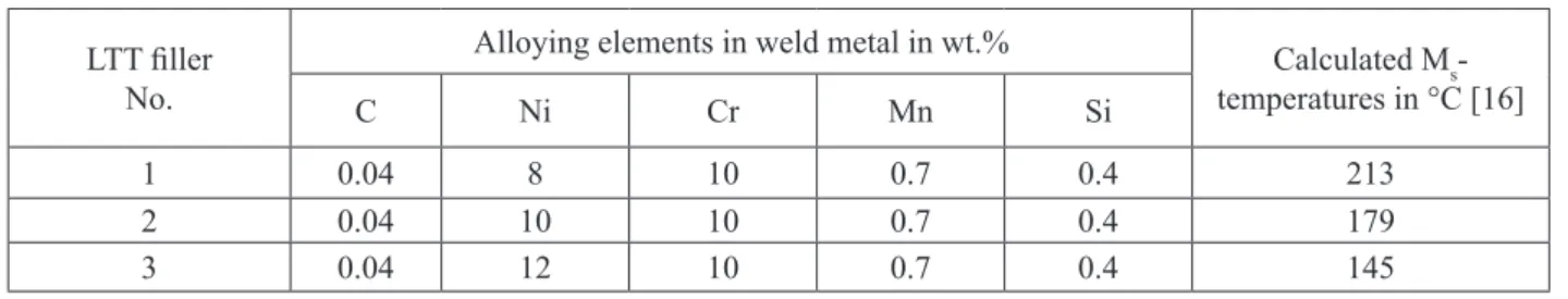
LTT welding material used in this work is presented in Table 1. Three different stick electrodes were applied to produce all-weld metal free from dilutions of parent material. The chemical composition was varied in terms of the nickel content, the amounts of all other elements were kept constant. The assumed transformation temperatures were determined by the formula of Steven and Haynes [16]. As a result of the increasing nickel content the Ms-temperature is shifted to lower values.
Table 1. Chemical composition of weld metal and calculated Ms-temperatures.
LTT iller No.
Alloying elements in weld metal in wt.% Calculated M
s -temperatures in °C [16]
C Ni Cr Mn Si
1 0.04 8 10 0.7 0.4 213
2 0.04 10 10 0.7 0.4 179
3 0.04 12 10 0.7 0.4 145
Synchrotron Analysis 2.2.
Synchrotron analysis was conducted at materials science beamline EDDI of the Hahn-Meitner-Institute (HMI) at BESSY,
3rd generation synchrotron facility in Berlin, Germany [17]. An
energy range of 20 to 150 keV for investigations is made available there. This condition allows simultaneous determination of all crystalline phases of a material within one experiment under a ixed diffraction angle. During a simulated welding heat cycle, diffraction lines were measured in discrete time steps of 8 s. Synchrotron analysis was conducted only for LTT – material No. 1 with 8 % Ni. Austenisation temperatures during heating as well as martensite formation temperatures during the cooling cycle could be analysed.
A special domed hot stage was used to realise a thermal cycle similar to welding conditions. Investigations using synchrotron radiation made special specimen preparation necessary. Chips with a diameter of 10 mm and a thickness of 0.3 mm were prepared from all-weld metal produced in multi-layer welding. The chip specimens were placed in the hot stage covered by a carbon dome which is penetrable for synchrotron radiation. Nitrogen was used as shielding gas. The thermal cycles for heating and cooling are summarised in Table 2. The cooling rate decreased at lower temperatures, since no active cooling was applied. Table 3 shows the parameters used for synchrotron analysis.
Table 2. Parameters for heating and cooling cycles.
Cycle Start temperature Finish temperature Heating/Cooling rate
1 ambient 1100 °C 500 K/min
2 1100 °C ambient max. 500 K/min
Table 3. Parameters for synchrotron analysis.
Primary beam cross section 1x1 mm²
Absorber 2 cm graphite
Diffraction angle 2θ = 14°
Measuring mode Relexion
Measuring time 8 s / spectrum
Thermal Analysis 2.3.
Type K thermocouples were used. Table 4 shows the characteristics of this type.
Table 4. Characteristics of used thermocouples.
Thermocouple Material Temperature range
type K NiCr(+) / Ni(-) 0 °C - 1200 °C
For the thermal analysis, welding was performed directly on a water cooled copper plate in order to obtain all-weld metal free from dilution. This procedure was conirmed by other authors, i.e. Martinez Diez [5]. After cooling down to ambient temperature, thermocouples were applied by resistance welding directly onto the weld metal. Reaustenisation was achieved by heating up to 900 °C using an mufle furnace. The material was then immediately immersed into hardening oil to ensure constant cooling conditions.
The thermal history was online recorded until ambient temperature was reached. The acquired data were analysed according to the methodology of Alexandrov and Lippold [15]. Transformation temperatures could thus be determined from discontinuities in the thermal history caused by latent heat release associated with phase transformations. The discontinuities can be detected by calculating the difference of the measured thermal cycle from a reference thermal cycle, i.e. an exponential function obtained from regression analysis. Thermal analysis were applied for all investigated LTT - materials and provided martensite start temperatures.
Results and Discussion 3.
Phase Transformation during Heating 3.1.
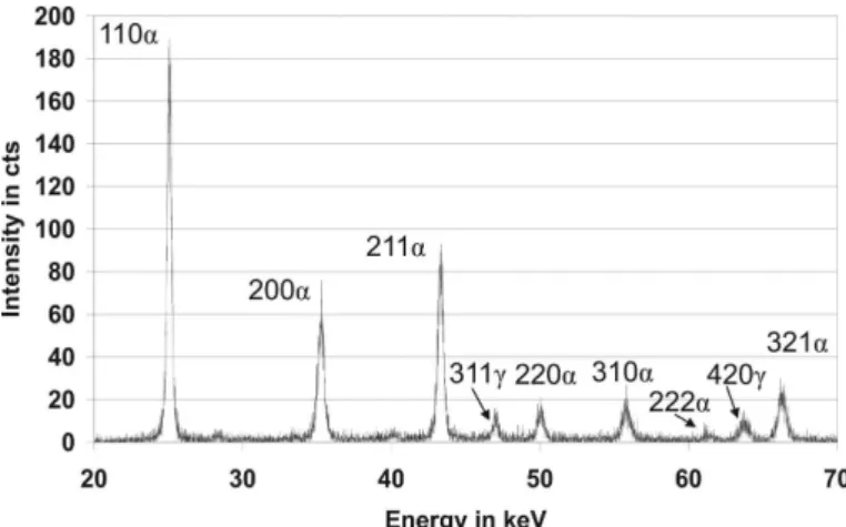
Before starting the heating cycle, diffraction patterns of sample material were recorded at ambient temperature. The result is shown in igure 1. The diffraction lines are either martensitic or austenitic. No other diffraction lines were found.
Figure 1. Diffraction pattern at ambient temperature showing martensite and austenite diffractions (initial condition).
Specimen showed beside martensite peaks distinct diffractions from the austenitic spectrum. Diffraction patterns were then recorded during heating up to a temperature of 1100 °C. In the following, a 2D-density plot of the diffraction patterns during heating is given as a function of the time, respectively temperature (see igure 2). In this plot, high intensive diffraction peaks are represented by white coloured lines. Density plots are useful as a irst tool to identify changes the in diffraction patterns. Thus, areas of interest can be easily located and analysed in detail in the respective spectra. All visible diffractions are marked within the igure.
Figure 2. Density plot of diffraction patterns during heating cycle. Austenisation range is characterised by overlapping
martensite and austenite diffractions.
During heating, a slight movement of the lines to lower energy regions is visible due to thermal expansion and associated change in atomic spacing. In the distribution of the lines, a change is observed in a temperature range between 400 °C and 600 °C. This temperature range indicates the austenisation and is subsequently speciied.
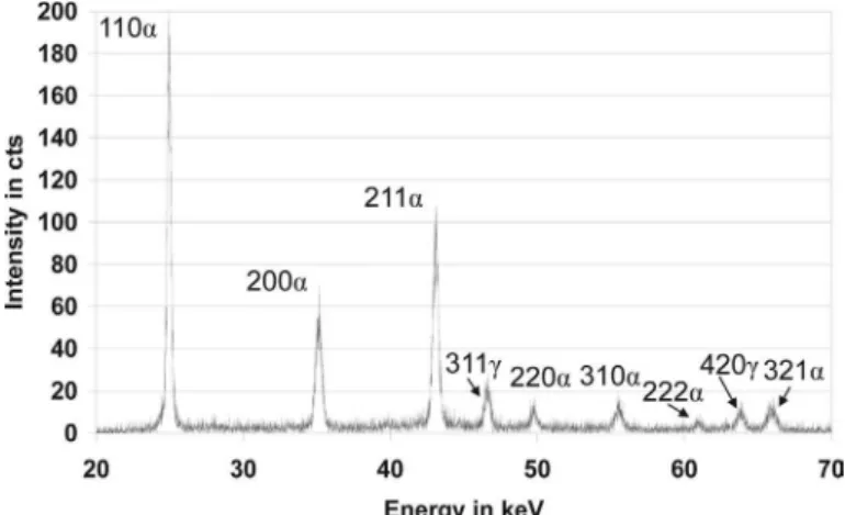
Figure 3 shows the diffraction pattern at a temperature of 438 °C, shortly before austenisation started. This pattern is still identical with the one shown for ambient temperature given in igure 1.
At a temperature of Ac1 = 507 °C, the pattern has changed.
For the irst time, additional austenite peaks appeared, see igure 4. The austenisation started at this point in time. The amount of martensite was decreased here and, hence, the intensity of
peaks was reduced. Even at a temperature of Ac3 = 577 °C, all
Figure 3. Diffraction pattern at T = 438 °C showing martensite and austenite diffractions shortly before austenisation.
Figure 4. Diffraction pattern at Ac1 = 507 °C showing
martensite and austenite diffractions at beginning austenisation.
Figure 5. Diffraction pattern at Ac3 = 577 °C showing austenite
diffractions at completely austenised material.
The material had completely austenised. This phase transformation started and inished quite simultaneously for all recorded diffraction lines. Further changes in the spectra were not existent. The point in time and temperature of austenisation could deinitely be established. As a irst result, the austenisation temperature for the studied LTT - material No. 1 is given in Table 5. The relatively large conidence intervals result from
the temperature range which was passed through during the measuring time of 8 s per recorded spectrum.
Table 5. Austenisation temperatures for LTT welding material.
Temperature of austenisation
LTT iller 8 % Ni
Ac1 507 ± 68 °C
Ac3 577 ± 56 °C
Phase Transformation during Cooling 3.2.
Synchrotron Analysis 3.2.1.
Considering the diffraction patterns during cooling, it is remarkable that retransformation into martensite starts at different temperatures for respective diffraction lines. It is obvious that
martensite diffraction lines at lower energies, i.e. 110α at 25 keV,
appear earlier than diffractions at higher energies, see igure 6. An explanation for that phenomenon could be the fact that diffractions at lower energies represent surface near penetration depths, whereas due to the temperature gradient martensite transformation starts earlier compared to core regions. Figure 7 shows the start of the transformation at Ms = 195 °C. The irst martensite peak 110α appears here slightly overlapped by austenite 111γ.
Figure 6. Density plot of diffraction patterns during cooling cycle. Start of martensite transformation is characterised by
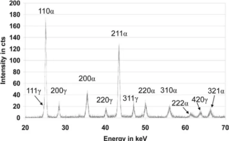
Figure 7. Diffraction pattern at Ms = 195 °C showing martensite and austenite diffractions. Zoomed area represents energy
range including irst visible martensite diffraction.
When transformation continues, further diffraction lines arise at higher energies. At a temperature of T = 108 °C (igure 8), diffraction peaks from martensite phase are completely developed and no further qualitative change in diffraction pattern during cooling down to ambient temperature is apparent.
Figure 8. Diffraction pattern at T = 108 °C for specimen No. 1 showing martensite and austenite diffractions.
The phase transformation obviously decays at a Temperature
Td = 35 °C with some retained austenite, clearly visible from
pronounced austenite diffraction lines, shown in igure 9. This Temperature cannot be assumed as Mf, since retained Austenite is still present. The Temperatures determined from synchrotron analysis during cooling are summarised in Table 6.
Table 6. Relevant temperatures obtained during cooling of LTT - material No. 1
Temperature LTT iller
8 % Ni
Ms 195 ± 6 °C
Td 35 ± 1 °C
Figure 9. Diffraction pattern at Td = 35 °C for specimen No.
1 showing martensite and austenite diffractions (martensite formation decays).
Thermal Analysis 3.2.2.
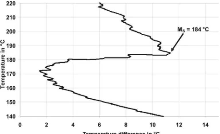
The temperature curves measured during cooling of LTT weld metals are shown in igure 10. Effects of different phase transformation temperatures become already apparent here. A detailed analysis determining the deviation compared to a reference thermal cycle, using an exponential or cubic function, revealed the Ms - temperatures of the investigated material, see igure 11. Also the irst and second deviation of the thermal
cycle is helpful to identify the Ms - temperature.
The Ms temperatures show a linear decrease with increasing nickel content, see Table 7. Compared to the synchrotron analysis, the values of LTT - material No. 1 are slightly lower. The reason for that could be the different size of specimens used in the investigations. In the synchrotron analysis, the investigated volume was very small compared to the thermal analysis of weld metal. This is the reason why the bulk temperature of martensite transformation of the weld in the latter case differs from the
point analysis (1 mm2) when using synchrotron radiation.
However, concerning measurement uncertainties, the values
differ only by 5 °C. Further, the results indicate that the Ms -
temperature is relatively unaffected by the cooling conditions since, synchrotron and thermal analysis exhibit comparatively slow and rapid cooling rates.
Figure 10. Ms - temperatures of investigated LTT materials
Figure 11. Deviation of measured and reference thermal
cycle of LTT – material No.1 (8 % Ni) coinciding with Ms –
temperature.
Table 7: Comparison of Ms - temperatures determined by
synchrotron and thermal analysis to calculation by Steven and Haynes [16]
LTT - material No. 1 No. 2 No. 3
Ni content 8 % Ni 10 % Ni 12 % Ni
synchrotron 195 °C -
-thermal 184 °C 90 °C 39 °C
calculated 213 °C 179 °C 145 °C
Results also prove that the linear calculation formula by Steven and Haynes shows good coincidence only for the LTT - material with a nickel content of 8 %. With higher nickel contents results are lower than calculation has predicted. The advantages of diffraction analyses i.e. synchrotron radiation, can be stated as follows. Contrary to techniques using secondary effects, like changes of temperature in thermal analysis, diffraction analysis gives the opportunity of direct observation of occurring phase transformations. Since peak positions in the spectra are directly relatable to different phases no additional analysis into the microstructure is necessary. In addition, diffraction measurements permit quantitative determination of the amount of individual phases, what is planned for future studies. Furthermore, using high sampling rates, the exact determination of start and inish temperatures i.e. Ac1 and Ac3 becomes possible.
Conclusions 4.
Synchrotron as well as thermal analysis was conducted on a speciic selection of Low Transformation Temperature (LTT) welding material. Nickel content was varied within 8 % to 12 %. Also the inluence of different cooling conditions was investigated. At the present state of investigations into the transformation temperatures of LTT - iller material, the following conclusions can be drawn:
For the irst time, transformation temperatures during heating 1.
and subsequent cooling of Low Transformation Temperature
(LTT) welding material could be assessed by use of synchrotron radiation. For the investigated weld metal with a chromium content of 10 % and a nickel content of 8 %, austenisation takes place within a temperature range between 507 °C and 577 °C. Martensite transformation occurs at 195
°C and decays at 35 °C. Based on these measurements, Ms -
temperatures of further LTT - material with varying nickel content could be assessed by thermal analysis.
The results show that the temperature of martensite start 2.
is strongly dependent on the content of alloying elements.
With higher nickel content, the Ms - Temperature is shifted
to lower temperature regions. This should also lead to a shift of the martensite inish temperature; e.g. in case of higher nickel contents to below ambient temperature with respective amounts of retained austenite.
The temperature of martensite formation is unaffected by 3.
cooling conditions in the studied case. Results indicate almost equal values during the events of slow and rapid cooling what gives a stable working frame independently of cooling conditions when applying LTT - material.
The investigated LTT - material is qualiied for creating 4.
compressive residual stresses in the weld and HAZ by using the effect of martensite transformation at low temperatures.
Acknowledgments 5.
The authors would like to especially acknowledge Lincoln Electric Europe for provision of the welding consumables.
The authors are also grateful to the team at the EDDI-beamline at Bessy Berlin for their kind support.
References 6.
OHTA, A.; WATANABE, O.; MATSUOKA, K.; SHIGA, [1]
C.; NISHIJIMA, S.; MAEDA, Y.; SUZUKI, N.; KUBO, T. Fatigue Strength improvement by using newly developed low transformation temperature welding material, Welding in the World, 43, 6, p.38-42, 1999.
SUZUKI, N.; OHTA, A.; MAEDA, Y. Repair of fatigue [2]
cracks initiated around box welds using low transformation temperature welding material. Welding International (2), p.112-117, 2004.
ZENITANI, S. et al. Prevention of Cold Cracking in [3]
High strength Steel Welds by Applying Newly Developed Low
Transformation-Temperature Welding Consumables. 6th INTERN.
TRENDS IN WELDING RESEARCH CONFERENCE, 15.-19. April, 2002, Pine Mountain. Proceedings…Materials Park, OH: USA, 2003. p.569-574.
MIKAMI, Y.; MOCHIZUKI, M.; TOYODA, M. In-Process [4]
MARTINEZ DIEZ, F. The Development of a Compressive [5]
Residual Stress Field Around a Weld Toe by Means of Phase Transformations, IIW - Doc. No. IIW-IX-2231-07, 2007.
MIKAMI, Y.; MORIKAGE, Y.; MOCHIZUKI, [6]
M.; TOYODA, M. Evaluation of Relationship between Transformation Expansion of Weld Metal and Welding Distortion through Numerical Simulation Considering Phase Transformation Effect, IIW - Doc. No. IIW-X-1582-05, 2005.
KROMM, A.; KANNENGIESSER, TH.; GIBMEIER, J.; [7]
GENZEL, CH.; VAN DER MEE, V. Determination of Residual Stresses in Low Transformation Temperature (LTT-) Weld Metals using X-ray and High Energy Synchrotron Radiation. IIW - Doc. No. IIW-II-1658-07, 2007.
ROCHA, DA S.A.; HIRSCH, T.: Fast X-ray diffraction [8]
phase and stress analysis during complete heat treatment cycles of steel, Materials Science and Engineering A, vol. 395, p.195-207, 2005.
ELMER, J.W.; PALMER, T.A.: Phase Mapping and Direct [9]
Observations of Phase Transformations during Arc Welding of 1045 Steel, Metallurgical and Materials Transactions A, vol. 37A, July, p.2171-2182, 2006.
ZHANG, W.; ELMER, J.W.; DEBROY, T.: Kinetics of [10]
Ferrite to Austenite Transformation During Welding of 1005 Steel, Scripta Materialia, vol. 46, p.753-757, 2002.
ELMER, J.W.; PALMER, T.A.; ZHANG, W.; DEBROY, [11]
T.: Time resolved X-ray diffraction observations of phase transformations in transient arc welds. Science and Technology of Welding and Joining, Vol. 13, No. 3, p.265-277, 2008.
BABU, S.S.; ELMER, J.W.; VITEK, J.M.; DAVID, S.A.: [12]
Time-resolved X-ray diffraction in Fe-C-Al-Mn steel welds, Acta Materialia, vol. 50, 2002, p.4763-4781, 2002.
TERASAKI, H.; KOMIZO, Y.; YONEMUIRA, M.; [13]
OSUKI, T.: Time-Resolved Analysis of Phase Evolution for the Directional Solidiication of Carbon Steel Weld Metal. Metallurgical and Materials Transactions A, vol. 37A, p.1261-1266, 2006.
KANNENGIESSER, TH.; KROMM, A. Inluence [14]
of transformation temperature on residual stresses using low transformation temperature welding material, IIW
INTERNATIONAL CONGRESS, 2nd LATIN AMERICAN
WELDING CONGRESS AND XXXIV CONSOLDA, 2008, Sao Paulo. Proceedings… (in press).
ALEXANDROV, B.T.; LIPPOLD, J.C. Methodology for [15]
In-situ Investigation of phase transformations in welded Joints, IIW - Doc. No. IIW-IX-2114-04, 2004.
STEVEN, W.; HAYNES, A.G. The Temperature of [16]
Formation of Martensite and Bainite in Low-alloy Steels, Journal of the Iron and Steel Institute, August, p.349-359, 1956.
GENZEL, CH.; DENKS, I.A.; GIBMEIER, J.; KLAUS, [17]