Preliminary Definition of CORTEX
System Architecture
C. Brudna, V. Cahill, A. Casimiro, R. Cunningham,
J. Kaiser, R. Meier and P. Veríssimo
DI-FCUL
TR–03–17
July 2003
Departamento de Informática
Faculdade de Ciências da Universidade de Lisboa
Campo Grande, 1700 Lisboa
Portugal
Technical reports are available at http://www.di.fc.ul.pt/tech-reports. The files are stored in PDF, with the report number as filename. Alternatively, reports are available by post from the above address.
Project IST-2000-26031
CO-operating Real-time senTient objects:
architecture and EXperimental evaluation
Preliminary Definition of CORTEX System
Architecture
CORTEX Deliverable D4
Version 2.0
Revisions
Rev. Date Comment
1.0 22/02/2002 Draft document for internal review
1.1 06/03/2002 Added introduction - still draft document
2.0 04/04/2002 Final document
Editor
Ant´onio Casimiro, University of Lisboa
Contributors
Cristiano Brudna, University of Ulm Vinny Cahill, Trinity College Dublin Ant´onio Casimiro, University of Lisboa
Raymond Cunningham, Trinity College Dublin J¨org Kaiser, University of Ulm
Ren´e Meier, Trinity College Dublin Paulo Ver´ıssimo, University of Lisboa
Address
Faculdade de Ciˆencias da Universidade de Lisboa Bloco C5, Campo Grande
1749-016 Lisboa Portugal
Contents
1 Introduction 5
2 CAN Level 7
2.1 Introduction . . . 7
2.1.1 General Architecture . . . 7
2.1.2 Achieving predictability of message transfer . . . 9
2.1.3 Achieving order of messages . . . 10
2.2 Preliminary definition of the network infrastructure . . . 11
2.2.1 The CAN-Bus infrastructure and protocols . . . 11
2.2.1.1 Dynamic configuration protocol for the assignment of short CAN node IDs . . . 13
2.2.1.2 Dynamic binding protocol for the assignment of event channel short IDs . . . 13
2.2.2 The TCP/IP infrastructure and protocols . . . 14
2.2.2.1 The dynamic binding protocol . . . 14
2.2.2.2 The gateway . . . 15
2.2.2.3 The Application Programming Interface (API) . . . 16
2.2.2.4 Target Environment . . . 16
3 Wireless Level 17 3.1 Introduction . . . 17
3.2 Wireless Networks . . . 17
3.3 Related Work . . . 18
3.3.1 Contention based approaches . . . 18
3.3.1.1 Scheduled based approach . . . 19
3.4 MAC protocol for Ad Hoc networks . . . 21
3.4.1 Protocol Introduction . . . 21
3.4.2 Protocol Basics . . . 22
3.4.3 Atomic Agreement . . . 23
3.4.4 Communication Between Cells . . . 25
3.4.5 Slot Allocation . . . 25
3.4.5.1 Non-empty Cell / Mobile host powers on . . . 26
3.4.5.2 Empty Cell / Mobile host powers on . . . 26
3.4.5.3 Non-empty Cell / Mobile host enters cell . . . 28
3.4.5.4 Empty Cell / Mobile host enters cell . . . 29
3.4.6 Slot Deallocation . . . 29
3.4.7 Protocol Extensions . . . 30
3.5 Acknowledgements . . . 31
4 TCB Architecture and Protocols 32 4.1 Introduction . . . 32
4.2 The Timely Computing Base Model . . . 32
4.3 TCB Services . . . 33 4.4 Programming Interface . . . 34
A CAN Messages 37
A.1 Format for normal Operation . . . 37 A.2 Message-Ids for the Dynamic Configuration Protocol . . . 37 A.3 Message Ids for the Dynamic Binding Protocol . . . 38
B Application Programming Interface (API) 39
B.1 Linux API . . . 39 B.2 RTLinux/C167 API . . . 40
1
Introduction
The objective of this work package is to define the system architecture of CORTEX, focusing on the components that are necessary to implement the communication abstractions developed in WP2. From an architectural point of view it is possible to consider two logical scopes, with different implications in terms of the problems to be dealt. In one hand there is a local scope, over which it makes sense to address issues such as the CORTEX node topology, the definition of local modules to support the required functionality, the problem of interfacing ”application” objects, and the provision of runtime support. One the other hand, there is a global scope, where the WAN-of-CAN structure envisaged in CORTEX is of fundamental importance, and where there is room to address issues like wireless operation, and interconnection and composition of CORTEX nodes.
In terms of the global scope, the basic infrastructure envisaged is composed of a global network (WAN) that comprises substructures subsumed by the abstraction of a Controller Area Network (CAN). This WAN-of-CAN structure is fundamental to CORTEX for various reasons:
• it provides a good and natural abstraction of possible communication infras-tructures to be deployed in real settings (as identified in the application sce-narios of WP1-D1);
• it allows for a separation of concerns when dealing with Quality of Service (QoS) issues, being possible to address stronger QoS requirements in the con-text of the CAN abstraction, weaker QoS requirements in the concon-text of WANs, and being the mapping between different QoS levels addressed in the context of gateway components, logically defined in the middle of these levels;
• it provides an hierarchical structure which may be fundamental to achieve scalability.
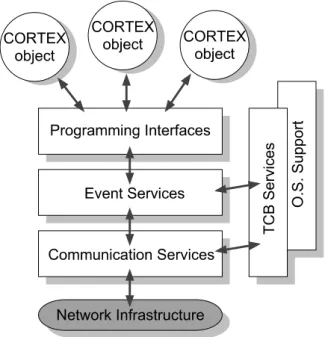
In terms of the local scope, an important issue is the definition of the internal architecture of a CORTEX node. However, at this initial stage of the project this architecture should be generic enough to encompass all the possible functional differ-ences relative to entities considered in the WAN-of-CAN structure (e.g., gateways, CORTEX objects). Hence, the approach in this early stage has been to identify the several building blocks that may be needed and the possible relations among them. These generic building blocks address several important aspects, such as interfaces, the services supporting interaction and cooperation, and other services related with the provision of non-functional requirements (like services providing context aware-ness or providing time and timeliaware-ness information). In this preliminary stage of the project some of these basic building blocks have already been identified, resulting from on-going work in all work packages. Figure 1 illustrates what may possibly be the fundamental structure of a CORTEX node, which obviously will be refined and updated during the project lifetime, and presented in forthcoming deliverables.
The present deliverable provides some preliminary results that serve both the above directions of work: the definition of a WAN-of-CAN structure and compo-nents, and the definition of a internal structure of CORTEX nodes.
Section 2 defines a preliminary prototype of a WAN-of-CAN structure based on CAN-bus for the CAN level and on a TCP/IP network for the WAN level. In
Figure 1: Preliminary architecture of a CORTEX node.
particular, it provides preliminary protocol definitions to support the communication abstractions defined in WP2, and addresses some important aspects related with predictability of message transfer and ordering of messages.
Section 3 focusses on wireless infrastructures as a key technology to implement many of the properties of applications foreseen in CORTEX. The aspects of pre-dictable and reliable behavior, which are particularly relevant in the CORTEX project, are dealt special attention in this section, with the description of a new medium access protocol that specifically takes them into account.
Finally, Section 4 describes the Timely Computing Base, which can be seen as a special architectural component serving the whole system and providing crucial time related services. These services can be used, for instance, to define protocols or middleware components that implement some of the abstractions defined in WP2 (deliverable WP2-D3 presents a paper where the services of the TCB are used to develop an adaptive QoS mechanism).
2
CAN Level
2.1
Introduction
2.1.1 General Architecture
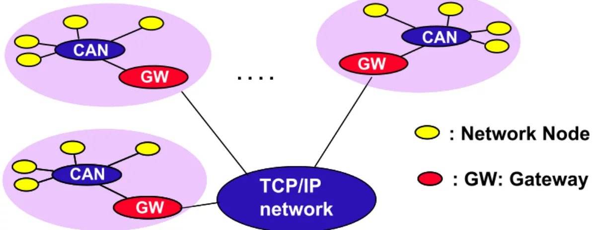
The WAN-of-CAN structure is the central architectural model in CORTEX. This section defines the general architecture and gives a preliminary specification of a two-level WAN-of CAN infrastructure. At this stage, emphasis is put on the definition of a predictable protocol for CANs and the basic functions of a gateway.
The general architecture is to connect islands of tight control which need a pre-dictable communication facility by a WAN with less stringent requirements. We currently focus on a two level protocol hierarchy, a CAN-Bus (Controller Area Net-work [13]) and a TCP/IP netNet-work, which may include wireless links. Figure 2 depicts the general structure.
:
Network Node
TCP/IP
network
GW CAN. . . .
GW GW CAN CANTCP/IP
network
GW CAN. . . .
GW GW CAN CAN: GW:
Gateway
Figure 2: Structure of the WAN-of-CANs
The intentions of this preliminary protocol definition are to provide a sufficient level of detail for a prototype to be developed in the next stage of CORTEX. The purpose of this early prototype will be:
• To provide a first infrastructure for the publisher/subscriber protocol defined in WP2.
• To study the temporal behavior of a gateway.
• To study the conditions of message dissemination in networks with different characteristics.
• To provide a communication facility for mobile entities.
The approach therefore is to map the general publisher/subscriber model de-scribed in WP2-D3 on specific networks and define the protocols accordingly. This mapping can not be done independent of the technology used in the network layer. Although CORTEX will define appropriate abstract network layers in a later phase of the project, at the moment we choose available lower level technology to start with.
• A CAN-Bus1 for the local sensor/actuator network because of its widespread
use and its decentralized protocol.
• A TCP/IP network for the WAN because of its generality.
The system may be composed from largely differing hardware, i.e. the local nodes may be everything from an 8-Bit microcontroller included in a simple smart sensor to a high-end workstation, resulting in a heterogeneous environment. Hence, heterogeneity occurs on two levels: the node level and the network level. To support interoperability in this environment, we exploit the publisher/subscriber concept de-fined in WP2-D1 in many ways. Firstly to hide heterogeneity of nodes, all these nodes have the minimal requirement to support the publisher/subscriber protocol by providing an event channel handler (ECH) which can be realized very efficiently in terms of processing requirements and memory footprint. For the small micro-controllers in the prototype system, we have implemented the ECH and a simple real-time executive. As it is further described in [5] the implementation for the workstations is based on Linux for non-real-time communication, particularly for the communication via TCP/IP and RT-Linux for the predictable CAN communi-cation.
Heterogeneity on the network level is masked by the gateways (GW). Hetero-geneity here not only addresses the problem of protocol conversion, but also raises the need to handle different timing and reliability characteristics. The gateways thus are crucial components in this architecture in many respects to provide inter-operability across the networks. In this early prototype architecture the focus is to substantiate the benefits of the publisher/subscriber concept in such a collection of heterogeneous networks and therefore, on the functions of routing messages across the individual network boundaries and to act as a filter for CANs.
In the WAN-of-CAN structure, the networks may rely on completely different addressing and routing concepts. The gateway not only serves as a simple store and forward component but has to adapt two systems which rely on different models of communication. E.g. the CAN-Bus uses a broadcast mechanism. Hence, rather than a scheme which is based on specifying the destination of a message in an address, the content of a message is characterized by a message identifier. All nodes in the system receive the messages and are able to decide on the basis of the identifier to deliver or discard it. In the TCP/IP network, messages are routed by address and point-to-point connections are opened and maintained between communicating nodes. Therefore the gateway has to map one model to the other rather than just performing address forwarding or conversion. Additionally, a gateway has the function of a filter. Filtering is a central function if CORTEX and the gateway is a well suited architectural component which can perform this task. Because we choose the model of connected islands of tight control, the gateway shields the local network from external traffic. Only those messages will cross the gateway which explicitly either are imported or exported by the local cluster.
Interoperability between networks, of course, requires an unambiguous mecha-nism for routing a message from the source to one or more destinations across multi-1There may be a confusion between the term CAN (Controller Area Networks) used with
a general meaning, e.g. in the WAN-of-CAN abstraction and the CAN-Bus as defined in the standard [13]. Therefore throughout the document, we use the term CAN-Bus when we refer to the specific standard.
ple heterogeneous networks. The routing is derived from the subject-based address-ing concept defined by the interaction model in WP2-D3. The publisher/subscriber model provides a unique identifier for the type of information carried by a mes-sage. This UID is a valid and agreed identification of a message independent of any particular addressing mechanism. Therefore, the UID and the dynamic binding to a specific routing mechanism is exploited to realize network wide communication in a WAN-of-CAN architecture.The gateway thus performs the dynamic binding of the unique message identifier to the network specific addressing mechanism when-ever it crosses a network boundary. Caching techniques are used to improve the performance of this mechanism.
2.1.2 Achieving predictability of message transfer
A main objective of CORTEX is to achieve the predictability of message transfer to enable cooperation. This is particularly important for the CANs because they are supposed to connect smart sensors and actuators which jointly have to perform reactive control tasks. Predictability includes a temporal and a reliability aspect. The temporal aspect comprises the mechanisms to guarantee that messages are delivered according to an appropriate timing specification. The reliability aspect refers to the fault-model under which the timing guarantees can be achieved. A further requirement for cooperation in a control system is that all jointly acting components have a consistent view on the order of messages.
It is assumed that the system has to accommodate hard time, soft real-time and non-real-real-time message transfer simultaneously. A completely statically preplanned system seems to be a contradiction to the anticipated need to flexibly adapt to dynamic changes. However, there may be safety related functions in the system which need temporal and reliability guarantees which can not be achieved without a certain preplanning. As an example consider the stop function of a mobile robot. Distance sensors detecting an obstacle may transmit an emergency message. Depending on the speed of the robot, this message has to be transmitted with a known and guaranteed latency. The envisaged protocol relies on two principles:
1. Reserving message slots for hard real-time messages, and
2. Exploiting a dynamic priority scheme to schedule soft real-time messages. To meet the reliability requirements, time redundancy is used, i.e. every message is sent up to n times where n is the anticipated omission degree. Therefore, the length of the message slot has to be adjusted accordingly. Usually, the statically assigned message slots have a severe impact on the overall bandwidth of the network. Moreover, because emergency situation do not occur frequently, most of these slots are just wasted in a usual TDMA scheme. In the protocol developed here, a dynamic priority mechanism is exploited to overcome this drawback. If a message slot is not used by a hard time message, it can be used by a soft time or a non real-time message. The system distinguishes three classes of messages according to their priorities:
1. All hard real-time messages have a single fixed priority which is just the highest possible value. Two hard real-time messages always have disjoint,
non-overlapping message slots and therefore never compete with another hard real-time message for network access.
2. Soft real-time messages have priorities related to their deadlines. However, these priorities can never reach the level of a hard real-time message. There-fore, if a hard real-time message is scheduled in the respective time slot, a soft-real-time message can never prevent its bus access. Because priorities of soft real-time messages are related to their deadlines they are effectively scheduled according to an earliest deadline first scheme (EDF).
3. Non real-time messages have a range of fixed low priorities.
The reason why hard real-time messages only need a single priority is that they are transferred in their predefined slots and this transfer is triggered by global time. Hence, two hard real-time messages are never transferred at the same time and, as a consequence, never have to compete with another hard real-time message on the Bus. Soft real-time messages can be issued at any time. Because their priority is always lower than the one for hard real-time messages, they will never get bus access in a reserved slot. The same applies for non real-time messages.
The dynamic priority scheme outlined above can be used for CSMA networks including the CAN-Bus, and wireless LAN (802.11) [17].
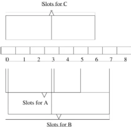
2.1.3 Achieving order of messages
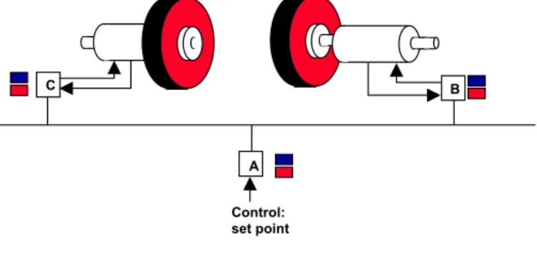
Cooperative real-time actions need consensus about which action to be performed and when to perform the action. Consider the simple example depicted in Figure 3. Two motors spin synchronously to move a robot. The main objective is to guarantee synchronism of the motors. For this purpose the motor controllers B, C communicate sending actual speed and, in case of a serious local problem an alarm message. Additionally, the speed of the motors can be adjusted externally by defining a new set-point. Even if the command to adjust the speed to the actual set-point may not be considered to be a hard real-time message, it is obvious that it has to be delivered to both motor controllers at the same time and, if multiple commands are issued, in the same order. This firstly requires that the command actually arrives at both nodes, a problem of reliable message transfer, and secondly, that there is a very small relative jitter for the delivery of messages at the distinct controllers.
time. Because their priority is always lower than the one for hard real-time messages, they will never get bus access in a reserved slot. The same applies for non real-time messages.
The dynamic priority scheme outlined above can be used for CSMA networks including the CAN-Bus , and wireless LAN (802.11) [KLJ00].
1.3 Achieving order of messages
Cooperative real-time actions need consensus about which action to be performed and when to perform the action. Consider the simple example depicted in Fig.2. Two motors spin synchronously to move a robot. The main objective is to guarantee synchronism of the motors. For this purpose the motor controllers B, C communicate sending actual speed and, in case of a serious local problem an alarm message. Additionaly, the speed of the motors can be adjusted externally by defining a new setpoint. Even if the command to adjust the speed to the actual setpoint may not be considered to be a hard real-time message, it is obvious that it has to be delivered to both motor controllers at the same time and, if multiple commands are issued, in the same order. This firstly requires that the command actually arrives at both nodes, a problem of reliable message transfer, and secondly, that there is a very small relative jitter for the delivery of messages at the distinct controllers.
Fig. 2 Example of a control system
If a new set point can be defined by multiple sources, or, more general, multiple messages which influence the motor speed are possible, it also has to be guaranteed, that the order of messages is the same for the two motor controllers. If messages have deadlines, they can be delivered at the deadline thus fulfilling the requirement of low jitter. However, soft real-time messages may miss their deadlines. Even in these situations, the order of messages has to be maintained as sketched in the example.
The mechanism provided usually is referred to as atomic totally ordered broadcast. For the CAN-Bus the following properties have to be guaranteed by the protocol:
1. All hard real-time message are delivered in deadline order in all nodes before the deadline expires.
2. All soft real-time message are deliverd in the order of their deadlines. In the case of equal deadlines, they are deliverd synchronously in all nodes according to their Message ID.
Control: set point
A
C B
Figure 3: Example of a control system
If a new set point can be defined by multiple sources, or, more general, multiple messages which influence the motor speed are possible, it also has to be guaranteed,
that the order of messages is the same for the two motor controllers. If messages have deadlines, they can be delivered at the deadline thus fulfilling the requirement of low jitter. However, soft real-time messages may miss their deadlines. Even in these situations, the order of messages has to be maintained as sketched in the example.
The mechanism provided usually is referred to as atomic totally ordered broad-cast. For the CAN-Bus the following properties have to be guaranteed by the pro-tocol:
1. All hard real-time message are delivered in deadline order in all nodes before the deadline expires.
2. All soft real-time message are delivered in the order of their deadlines. In the case of equal deadlines, they are delivered synchronously in all nodes according to their Message ID.
3. Non real-time messages are delivered in the order of their message ID.
The protocol is based on the reliable and timely message delivery described above. A detailed description is provided in [16].
2.2
Preliminary definition of the network infrastructure
This section describes the mapping of the components of the publisher/subscriber protocol like publisher, subscriber and event channels to an underlying network. In this preliminary definition, we focus on a CAN-Bus for the more tightly coupled ”islands of control” and to TCP/IP networks for WAN communication.
The main components of the communication architecture are: • The components of the CAN-Bus infrastructure.
• The components of the TCP/IP infrastructure.
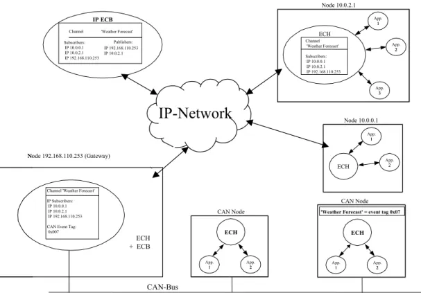
• The gateway that allows to have event channels across network boundaries. Figure 4 sketches the components of the architecture and includes an example for an event channel ”weather forecast”. As described in WP2-D3, there is an ECH (Event Channel Handler) in each node that provides all the support for local objects and a ECB (Event Channel Broker) that provides the dynamic binding of event channels to an underlying addressing mechanism. A gateway is a special element that integrates ECH and ECB functions.
From the point of view of an application the communication infrastructure pro-vides the same services for objects whether they reside on TCP/IP nodes or on a CAN node.
2.2.1 The CAN-Bus infrastructure and protocols
The communication over the CAN-Bus is supported by the local CAN-ECH and the CAN-ECB. To support the publisher/subscriber way of communication and exploit the dynamic priority scheme outlined above, the 29-bit CAN-Bus identifier (CAN 2.0 B [BOSCH91]) is divided into three fields for event messages:
3. Non real-time messages are delivered in the order of their message ID.
The protocol is based on the reliable and timely message delivery described above. A detailed description is provided in [Kai00].
2. Preliminary definition of the network infrastructure
This section describes the mapping of the components of the publisher/subscriber protocol like publisher, subscriber and event channels to an underlying network. In this preliminary definition, we focus on a CAN-Bus for the more tightly coupled "islands of control" and to TCP/IP networks for WAN communication.
Fig. 3 Components of the Architecture The main components of the communication architecture are: - The components of the CAN-Bus infrastructure.
- The components of the TCP/IP infrastructure.
- The gateway that allows to have event channels across network boundaries.
Fig. 2 sketches the components of the architecture and includes an example for an event channel "weather forecast". As described in WP2-D3, there is an ECH (Event Channel Handler) in each node that provides all the support for local objects and a ECB (Event Channel Broker) that provides the dynamic binding of event channels to an underlying addressing mechanism. A gateway is a special element that integrates ECH and ECB functions.
Channel 'Weather Forecast' Subscribers: Publishers: IP 10.0.0.1 IP 192.168.110.253 IP 10.0.2.1 IP 10.0.2.1 IP 192.168.110.253 IP ECB Channel 'Weather Forecast' Subscribers: IP 10.0.0.1 IP 10.0.2.1 IP 192.168.110.253 ECH App. 11 App. 22 App. 33
Channel 'Weather Forecast' IP Subscribers:
IP 10.0.0.1 IP 10.0.2.1 IP 192.168.110.253 CAN Event Tag:
0x007 App. 11 App. 22 ECH App. 11 App.22 ECH CAN Node CAN Node Node 10.0.2.1 ECH App. 11 App. 22 Node 10.0.0.1 Node 192.168.110.253 (Gateway)
'Weather Forecast' = event tag 0x07
CAN-Bus
IP-Network
ECH + ECB
Figure 4: Components of the Architecture • a priority field
• a field identifying the sending node. This field is necessary to ensure uniqueness of the CAN-Bus messages. It is referred as TxNode.
• a field which identifies the event channel. This event channel identifier is dynamically assigned. It is referred as ”event tag ”.
The detailed format of the event message is defined in the Appendix A. To unambiguously identify event channels and network nodes, long unique identifiers (UIDs) are assigned to them respectively. However, because the restricted message length of the CAN-Bus, these UIDs are mapped to the short, temporary identifiers, the event tag as indicated above. Further, rather than carry event tags in the data part of the message, they are mapped to the CAN-Bus message IDs. This has two major advantages:
1. The hardware of the CAN-Bus communication controller is exploited to filter event messages.
2. To reserve the rare available space strictly for the payload of CAN messages. To dynamically include nodes in the CAN-Bus and perform the assignment of event tags, two protocols necessary:
1. The dynamic configuration protocol for the assignment of short CAN node IDs.
2. The dynamic binding protocol for the assignment of event channel short IDs. 12
2.2.1.1 Dynamic configuration protocol for the assignment of short CAN node IDs
This protocol allows to dynamically connect new nodes to the CAN-Bus network. It is performed between a CAN-Bus node and the ECB. It solves the problem that uniqueness of message-IDs has to be assured in a CAN-Bus network [13]. The short CAN node ID TxNode of the sending node is used to guarantee this property. TxN-ode is derived from the 64 Bit nTxN-ode UID during the configuration phase. Whenever a new CAN node is dynamically connected and started up, a specific configuration protocol between the node and the ECB is carried out. During the configuration protocol, the node sends its 64-bit identifier in 8 consecutive messages. This is nec-essary because these messages must not contain any data part which could lead to inconsistencies on the physical CAN -Bus layer. Therefore, all information has to be transmitted in 1-Byte packets encapsulated in the CAN-Bus message identifier (Re-quest Short ID, RSI, see Appendix A). After receiving the last part, the CAN-ECB transfers a 7-Bit short identifier referred as TxNode to the CAN node in a dedicated message (Supply Short ID, SSI, see Appendix A). Once the CAN node has a short node ID it can participate in the ordinary communication and start subscribing or publishing to an event channel.
2.2.1.2 Dynamic binding protocol for the assignment of event channel short IDs
This protocol performs the dynamic binding of an event channel UID to a short ID in the CAN message ID. The 14-Bit field is refereed as an ”event tag”. The protocol is carried out between the respective ECH and the ECB.
To subscribe to a channel an object uses the 64-bit event channel UID. The object will send a request to the local ECH using the long UID (Request etag, see Appendix A). The ECH has to proceed as follows:
1. The ECH has to register the new subscriber. For this purpose it maintains a list which contains all local objects which have subscribed to some event channel. This is necessary to notify a local object whenever an event published to that channel is recognized on the network. The ECH therefore updates its internal subscriber list with the new subscriber.
2. The ECH has to bind the event channel UID provided by the subscriber to a network address. If this binding has been done before (for another subscriber) the ECH just uses this information to detect a respective event message of the network and notify the subscriber. If not, the ECH has first to request the binding from the ECB. It submits the long UID to the ECB which returns a 14-bit short identifier short event tag (Supply etag, see Appendix A). This is used by the ECH to recognize any message broadcasted to the CAN-Bus related to the given channel.
To publish an event to an channel a similar procedure is used. The publisher, publishes an event using the 64-bit UID. As in the case discussed above, the ECH will:
1. Register the publisher. To do this, the ECH first checks its internal subscriber list whether such an entry already exists, i.e. any other local object already has subscribed to the same channel. If this is the case, the binding to an event tag has already been done before. The ECH notifies all local subscribers and broadcasts the event to the CAN-Bus.
2. If no entry in the local list exists, a new entry is created. The event channel UID is inserted and the ECH will request an 14-bit event tag from the ECB. Having preformed this binding, the event will be broadcasted to the network using the assigned event tag.
During normal operation, i.e. if the binding is performed, the ECH will check for each message on the broadcast medium, whether there are local subscribers and notify and forward the event message to them.
2.2.2 The TCP/IP infrastructure and protocols
In the same way as in the CAN-Bus, the communication in the TCP/IP part of the network is supported by the local ECH and the TCP/IP-ECB. The TCP/IP protocol differs from the CAN protocol in the following points:
1. It is a point-to-point protocol.
2. Addresses identify the destination of a message rather than the content. 3. Nodes are identified by a unique IP-address.
Therefore the protocol will differ substantially from the CAN-Bus protocol. The dynamic configuration protocol is not needed because each node has a IP address to be able to communicate (see also Figure 4).
2.2.2.1 The dynamic binding protocol
Because of the point-to-point communication in the TCP/IP network, a broadcast has to be transformed into a sequence of point-to-point messages. The API of the publisher/subscriber protocol has to be kept independent from a specific network. Therefore, the middleware has to maintain all the data structures which are neces-sary to achieve this transparency. Hence, the ECH has to maintain a registry that includes all subscribers of a local publisher. Whenever a publisher pushes an event to the event channel, the ECH has to map this to a sequence of individual messages to the destinations kept in its registry. The example in Figure 4 shows such lists for the IP-nodes.
As in the CAN-Bus, the publisher uses the event UID to push a message to an event channel. The local ECB handles this publication. Initially, the registry maintained for each event channel is empty, i.e. there are no subscribers registered. On the first time when a publisher pushes an event to the event channel, the ECH has to contact the ECB to register the new publisher. The ECB also maintains a registry where all available event channels are represented. Every entry in the registry maintains the assignments of an event channel to the (possibly multiple) publishers and the subscribers. The ECB first checks whether the event channel
to which a new publisher will send the event is already registered. If so, the ECB forwards the list of subscribers to the ECB which requested registration. If not, the ECB dynamically creates an entry in the registry assigned to the new event channel UID.
During a subscription operation an object provides the desired event channel UID and the local ECH adds the object in registry entry for that channel. After that, the ECH sends a message to the ECB requesting the subscription to this event channel. The ECB performs the assignment by the following steps:
1. The ECB includes the address of the requesting node in the registry entry for that event channel. This entry contains all known publishers and subscribers of the event channel.
2. The ECB sends the updated list of subscribers to all the publishers registered for this event channel.
In this way the UID of an event channel is dynamically bound to a list of pub-lishers and subscribers. During normal operation, the ECB is not involved because the ECH can use the local registry to address all subscribers of a local event channel directly.
2.2.2.2 The gateway
In order to allow the use both of CAN-Bus and TCP/IP networks the concept of a gateway must be introduced to the communication architecture. The gateway’s role is to provide means so that all applications running in every node will be able to receive event messages published on any network. An application running in a CAN node should be able to subscribe and receive events published on the TCP/IP network and vice versa. This capability must be provided by the communication architecture transparently for the application. The gateway has to support two directions of event flow:
1. TCP/IP-to-CAN-Bus and 2. CAN-Bus-to-TCP/IP.
The gateway behaves exactly like an ECH to the CAN-Bus and the TCP/IP network. In the direction TCP/IP-to-CAN-Bus, the gateway maintains a list of all event channels serviced by publishers in the TCP/IP network for which there are subscriptions from objects residing in the CAN system. The gateway hence appears like an ordinary ECH in all registries of the respective event channels.
For event flows from CAN-Bus to the TCP/IP network, the gateway maintains an ECH registry for each event channel serviced by a publisher on the CAN-Bus. Thus, all publishers on the CAN-Bus appear as local publishers in an ordinary node. Whenever an event message occurs on the CAN-Bus, the gateway behaves as an ECH with respect to the TCP/IP network.
2.2.2.3 The Application Programming Interface (API)
An API composed by a set of functions and structures is provided for applications. The abstract API for the publisher/subscriber only comprises the publish and the subscribe method. However, because we intend to build a first prototype of the protocol in the next stage of CORTEX, we defined a more detailed mapping of the publisher/subscriber protocol which considers a specific system environment. Appendix B presents details of the API.
2.2.2.4 Target Environment
The target environment is assumed to be composed by a set of heterogeneous hard-ware platforms running different versions of the publisher/subscriber protocol as described above.
1. TCP/IP-to-CAN-Bus and 2. CAN-Bus-to-TCP/IP.
The gateway behaves exactly like an ECH to the CAN-Bus and the TCP/IP network. In the direction TCP/IP-to-CAN-Bus, the gateway maintains a list of all event channels serviced by publishers in the TCP/IP network for which there are subscriptions from objects residing in the CAN system. The gateway hence appears like an ordinary ECH in all registries of the respective event channels.
For event flows from CAN-Bus to the TCP/IP network, the gateway maintains an ECH registry for each event channel serviced by a publisher on the CAN-Bus. Thus, all publishers on the CAN-Bus appear as local publishers in an ordinary node. Whenever an event message occurs on the CAN-Bus, the gateway behaves as an ECH with respect to the TCP/IP network. 2.2.3 The Application Programming Interface (API)
An API composed by a set of functions and structures is provided for applications. The abstract API for the publisher/subscriber only comprises the publish and the subscribe method. However, because we intend to built a first prototype of the protocol in the next stage of CORTEX, we defined a more detailed mapping of the publisher/subscriber protocol which considers a specific system environment. Appendix B presents details of the API.
2.2.4 Target Environment
The target environment is assumed to be composed by a set of heterogeneous hardware platforms running different versions of the publisher/subscriber protocol as describes above.
Fig. 4 The target environment
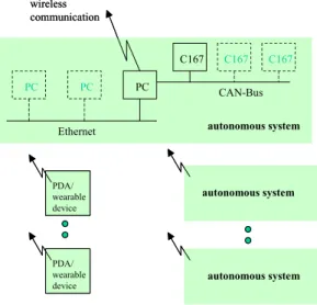
The intention behind this is a scenario where mobile robots or similar automotive components which internally use wired Ethernet and/or CAN-Bus networks are interoperating using
PC C167 PC PC C167 C167 CAN-Bus Ethernet wireless communication autonomous system autonomous system autonomous system PDA/ wearable device PDA/ wearable device PC C167 PC PC C167 C167 CAN-Bus Ethernet wireless communication autonomous system autonomous system autonomous system PDA/ wearable device PDA/ wearable device
Figure 5: The target environment
The intention behind this is a scenario where mobile robots or similar automo-tive components which internally use wired Ethernet and/or CAN-Bus networks are interoperating using wireless communication. Additionally, there may be wearable devices and PDAs (Personal Digital Assistants) integrated in the scenario. At the moment, the technology we consider consists of PC-hardware with Linux/RT-Linux, microcontroller boards equipped with Infineon C167 controllers and Compaq iPaq PDAs with wireless Ethernet (802.11). A view of this environment is shown on the Figure 5. Because there are implementations planned for three different sys-tems, the API has two slightly different forms: one for Linux/Unix and another for RTLinux/C167.
3
Wireless Level
3.1
Introduction
The widespread deployment and use of wireless data communications is generally recognised as being the next major advance in the information technology industry. In the long term, wireless data networks will represent a key enabling technology in the emergence of a new class of mission-critical computer systems as described in [1]. From a wireless communications perspective, key properties of these applications will be:
1. Mobility 2. Autonomy 3. Large scale
4. Time and Safety criticality 5. Geographical dispersion
In the next section, we introduce existing wireless networking technology in terms of these key properties. In the following section we cover existing research with particular reference to ad hoc networks and discuss how this research has yet to address the time and safety criticality properties mentioned above. In section 3.4, we describe a new medium access protocol for ad hoc networks that addresses these time and safety criticality properties that will be evaluated as part of the CORTEX project. This evaluation will also consider how this new protocol supports other key properties such as large scale, geographical dispersion and mobility.
3.2
Wireless Networks
Wireless networking technology can be considered under two distinct headings: 1. Infrastructure networks
2. Ad Hoc networks
This breakdown into two distinct areas depends on the level of independence afforded to the mobile hosts in the network.
In an Infrastructure network, mobile hosts can communicate with mobile hosts inside or outside their local area by first communicating with a fixed base station. The base stations are connected to each other by some backbone network. Base stations route packets, which are destined for other mobile hosts, to the correct base station that then forwards the message to the destination mobile host. Well known examples of this type of network include existing GSM networks [21], 3G networks [11] and the Point Coordination Function (PCF) of 802.11 [14].
Each of these infrastructure networks have a number of problems with regard to the key properties mentioned in the introductory section. For example in terms of scale and time criticality, both GSM and 3G networks have limited bandwidth com-pared to existing wired networking technologies and large latency since they require
two mobile hosts in the same area to communicate through a fixed base station. Also in terms of scale, the PCF of 802.11 has been shown to perform badly [27]. Finally in terms of autonomy, a mobile host in an infrastructure network is required to be within communication range of a base station to be able to communicate with other mobile hosts.
What differentiates an ad hoc network from and infrastructure network is that there are no fixed base stations with which a mobile host communicates. Each host in the network is capable of moving. Obviously, as there are no base stations, mobile hosts are more independent and the onus is on the mobile host to discover other mobile hosts in the network and to cooperate with these mobile hosts to enable the delivery of messages in the network.
In terms of increasing scale and geographical dispersion, the workload on the mobile hosts in an ad hoc network increases correspondingly. In addition, mobile hosts in the ad hoc network need to reach consensus on the transmission of timely and safety critical messages to prevent the well known hidden terminal problem [25] where one mobile host corrupts the messages of another mobile host.
3.3
Related Work
In this section, we review some of the existing techniques used to control medium access in wireless ad hoc networks. Typically, there are two main approaches used to access the wireless medium in an ad hoc network:
1. Contention 2. Scheduled access
These two techniques will be covered with particular emphasis on their safety and timeliness properties.
3.3.1 Contention based approaches
In these approaches, mobile hosts contend with each other for access to the wireless medium. In MACA [18] sensing of the wireless medium before transmitting is not done. Each mobile host transmits a “Request To Send” (RTS) control packet causing mobile hosts that receive this packet to defer. The destination of the RTS packet replies with a “Clear To Send” (CTS) control packet. On receiving the CTS packet, the successful mobile host then sends its data packet.
There is a possibility of collisions of the RTS packets using MACA. If a mobile host does not receive the CTS packet correctly then it executes a binary exponential back-off algorithm.
MACAW [3] builds on MACA by introducing a Data-Sending (DS) packet to indicate to mobile hosts that the RTS/CTS packet exchange was successful. In ad-dition, MACAW changes the back-off algorithm to include the current value of the back-off counter in the packet header field. Both 802.11 and FAMA-NTR [12] also build on top of MACA with each mobile host using carrier sensing before transmit-ting.
In each of these schemes, a mobile host does not have access to the wireless medium in a timely manner. In both MACA and MACAW, RTS control packets can
easily be corrupted due to two or more mobile hosts transmitting at approximately the same time. The possibility of this occurring in 802.11 is reduced (but not eliminated) by each mobile host waiting a random number of DIFS periods and sensing the wireless medium for other transmissions before transmitting.
In contrast to the above schemes, Sobrinho and Krishnakumar [24] use a black burst contention period to determine whether a mobile host gains access to the wireless medium or not. The mobile host sends a burst of energy of a known duration which is proportional to the amount of time that the mobile host has been waiting to access the medium. After transmitting the burst, the mobile host listens for other mobile hosts transmitting a longer burst. If there is a longer burst, then the mobile host defers its transmission. Otherwise the mobile host transmits its packet.
Markowski and Sethi [20] use a Contention Resolution algorithm (CRA) to sup-port the co-existence of hard, soft and non real-time data. A mobile host transmits its packet (of a fixed size) and then listens for feedback information from other mo-bile hosts as to whether a collision has occurred or not. If a collision has occurred, then the CRA is executed. The CRA at each mobile host uses a window of size n (where n is the known number of hosts participating in the protocol) and divides this into an active part and an inactive part. A mobile host in the active window transmits while those in the inactive window defer. If another collision occurs, then the hosts in the active window are split again into an active and an inactive part. This continues until a mobile host can successfully transmit.
The main disadvantage of the Sobrinho and Krishnakumar and the Markowski and Sethi medium access schemes is that they assume that participating mobile hosts are all within communication range of each other. Therefore, neither of these protocols deal with the hidden terminal problem.
3.3.1.1 Scheduled based approach
In this approach, mobile hosts negotiate a set of slots for individual mobile hosts, to transmit in, so that these transmissions are as free of collisions as possible. Once a mobile host has a slot allocated to it, it then has access to the medium in a timely fashion. However, this may not prevent another mobile host from also trans-mitting in this slot and therefore corrupting the mobile hosts transmission. These schedule-based approaches can be broken into two categories: topology-dependent and topology transparent scheduling.
Topology-dependent scheduling assigns time slots to mobile hosts (or links be-tween mobile hosts) within a two-hop neighborhood. As the topology changes, the time slots are reassigned in a distributed manner by the mobile hosts.
One approach, from Cidon and Sidi [9], uses a dedicated set of slots as a control segment to resolve conflicts and broadcast channel reservations. The number of dedicated slots used is proportional to the number of nodes in the network. Therefore as the number of mobile hosts in the network increases, the number of dedicated slots also increases.
Another topology-dependent approach, from Bao and Garcia-Luna-Aceves [19], uses identifiers for one-hop and two-hop neighbors to decide whether or not a mobile host (or a link between two mobile hosts) can use the current time slot. In addition to using one-hop and two-hop neighbor information, each mobile host uses a pseudo-random number generator (each mobile host using the same initial seed) to determine
which mobile hosts (or links) can be active in the current time slot.
From a timeliness point of view, whether or not a mobile host gains access to the time slot to transmit their packet depends on the current state of the pseudo-random number generator and the mobile hosts local two-hop topology information. Therefore a mobile host is unable to know when it will gain access to the wireless medium again. In addition, collisions can still occur using this approach when a mobile host does not have complete knowledge of the local one-hop and two-hop topology information, e.g. when network partitions begin to heal/merge.
In contrast to topology-dependent approaches, topology-transparent approaches, proposed by Chlamtac and Farago [8], and Ju and Li [15], allocate a collection of slots to a mobile host to use. The underlying idea of these approaches is that if a mobile host transmits in each of its allocated time slots then any neighbor of this mobile host will receive correctly at least one transmission from the mobile host. This is made possible by each mobile host using a unique code that determines which time slots a mobile host will use. However, one of the main limitations of the above two approaches is that the maximum number of neighbors of any mobile host is known and bounded. Another problem is that a transmitting mobile host does not know in which slot a particular neighbor can correctly receive their transmissions. Therefore, the mobile host must use all the slots allocated to it to ensure that at least one message is received correctly.
Another topology transparent protocol by Amouris [2] uses the position of a mobile host to determine in which slot that mobile host transmits in. In this work, space is divided into virtual geographic cells called space slots in a similar way to existing cellular networking techniques. A time slot is allocated to a space slot and due to spatial reuse, this time slot can be reused in space slots sufficiently far away. If there is more than one mobile host in a space slot, then the allocated time slot is used by the mobile hosts in a round-robin fashion by each mobile host maintaining a sorted list of the mobile hosts in the space slot.
As a mobile host moves from one space slot to another, it broadcasts a packet to inform mobile hosts in the new space slot and those in the old space slot of its arrival/departure. Another mobile host, in the new space slot, replies to this packet by transmitting a packet including the sorted list of mobile hosts located in the new space slot.
There are a number of problems with this protocol in terms of a mobile host having predictable access to the wireless medium. Firstly, the author of the paper does not specify how a mobile host that powers on in a space slot obtains a slot. A similar problem arises when two mobile hosts enter an empty cell or power on in an empty cell at the same time. These problems could easily be solved by allocating a number of time slots to allow mobile hosts to indicate their presence in the cell.
Another problem is that the sorted list of mobile hosts is replicated by each mobile host in the space slot (cell). Therefore, updates to this replicated data struc-ture need to be carried out in a consistent manner, otherwise there is a possibility of the sorted list becoming inconsistent across mobile hosts eventually resulting in collisions in the assigned time slot. Finally, the total bandwidth is divided by the number of space slots in a virtual (space) frame. Thus if there are a large number of mobile hosts in a space slot and a smaller number of mobile hosts in each of the neighboring space slots then the larger number of mobile hosts are still limited to the one assigned slot.
3.4
MAC protocol for Ad Hoc networks
This section describes a new Medium Access Control (MAC) Protocol for Ad Hoc networks, called the TBMAC (for Time-Bounded Medium Access Control) protocol, which provides mobile hosts with predictable access to the wireless medium. This new protocol exploits geographical information to allow mobile hosts predictable access to the wireless medium.
3.4.1 Protocol Introduction
To provide each mobile host with predictable medium access, the TBMAC needs (i) to reduce as much as possible the possibility of the transmissions of two or more mobile hosts from colliding and (ii) to detect collisions when they occur and to take some action to prevent these collisions from recurring.
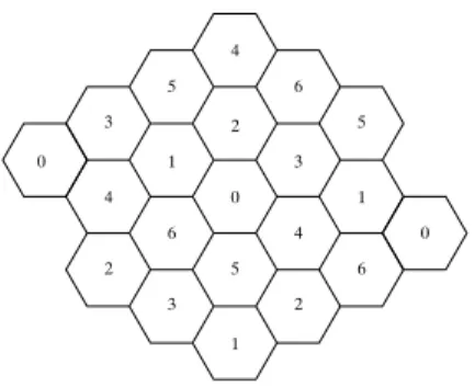
To reduce as much as possible the possibility of the transmissions colliding, the geographical area occupied by the mobile hosts is statically divided into a number of geographical cells. The cells can have arbitrary shape and size but for simplicity, let us assume that the cells are hexagons of equal size as illustrated in Figure 6. Each cell is numbered and each numbered cell is allocated a distinct CDMA spreading code (or radio frequency) to use. This allocation of codes to cells occurs statically and is done to allow channel re-use in a similar fashion to existing cellular networking techniques [22]. 6 1 2 3 4 5 0 2 4 3 5 4 0 6 3 1 2 6 1 5 0
Figure 6: Possible Cell configuration
The motivation behind dividing the area of coverage into a collection of cells is to reduce the possibility of the hidden terminal problem [25]. In order to achieve this, the width of a cell is related to the transmission range of the wireless tech-nology being used. By relating these, the probability of one mobile host hearing the transmission of another mobile host in the cell is increased thus reducing the possibility of the second mobile host in the cell beginning a transmission while the first mobile host’s transmission is in progress.
The division into cells does not completely solve (i) and (ii) above. Collisions can still occur as two hosts could transmit simultaneously thus corrupting each other’s packets at a receiving mobile host. When collisions do occur, we have not yet presented any mechanism to detect these collisions and to then prevent them from recurring (see section 3.4.1).
To further reduce the possibility of collisions, access to the medium within a cell is divided into two time periods:
1. Contention Free Period (CFP) 2. Contention Period (CP)
The division into a CFP and a CP is similar to the Point Coordination Function in the 802.11 standard [14] with the exception that the TBMAC CFP does not rely on one particular mobile host to act as an access point. Instead of using an access point, the TBMAC allows distributed agreement to be reached by the mobile hosts in a cell. Further details on how this agreement is achieved can be found in section 3.4.1
Both the CFP and the CP are divided into slots and each period lasts a well-known period of time. Once a mobile host has been allocated a slot in the CFP, it has predictable access to the wireless medium. The mobile host can then transmit data in its slot until it leaves the cell or fails. When a slot in the CFP is allocated to one mobile host in the cell, a mobile host sends a Null message in its slot even if it does not have a message to send.
Mobile hosts, that do not have CFP slots allocated to them, contend with each other to request CFP slots to be allocated to them in the CP. The CP is used by mobile hosts that have arrived into the cell or that have recently powered on in the cell. The steps required for a mobile host to be allocated a slot are covered in section 3.4.5.
Dividing access to the medium into two well-known time periods requires the clocks of all the mobile hosts in the network to be synchronised. Again equipping each mobile host with a GPS receiver would satisfy this clock synchronisation re-quirement. If GPS does not provide sufficient synchronisation precision, then a clock synchronisation protocol could be executed to synchronize the clocks of mobile hosts [23]. Periodically, in each cell at approximately the same time (based on the clock synchronisation precision), the CFP begins followed by the CP.
The rest of this section describes how the TBMAC protocol operates and is broken into the following parts:
1. Protocol Basics 2. Atomic Agreement
3. Communication Between Cells 4. Slot Allocation
5. Slot Deallocation 6. Protocol extensions 3.4.2 Protocol Basics
When a mobile host enters a cell and requires a slot in the CFP to be allocated to it, the mobile host first needs to learn whether there are other mobile hosts already in the cell with CFP slots allocated to them and what CFP slots have been allocated. For the moment, let’s ignore the case where there are no mobile hosts in the cell with CFP slots allocated to them. This case will be covered in detail in section 3.4.5.
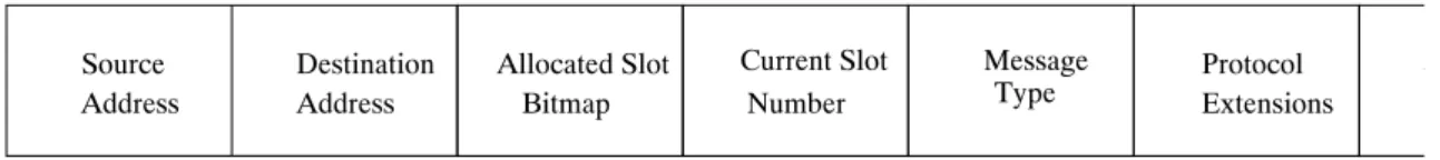
The newly arrived mobile host listens for one full CFP to pass before requesting a slot in the following CP. As part of each CFP slot message header (see Figure 7 ), there is an Allocated Slot Bitmap field. The Allocated Slot Bitmap field indicates the number of slots allocated in the cell. By receiving at least one message in the CFP correctly, the listening mobile host obtains the number of slots allocated and the position of these allocated slots in the CFP.
In addition to the Allocated Slot Bitmap field, a CFP message header also con-tains the Current Slot field which holds the value of the current slot being occupied and the type of the message being transmitted. In addition to these fields, the header contains an Extensions field (see section 3.4.7) and an Additional Info field. The Additional Info field is used for extra information depending on the type of the message being transmitted.
The Message Type field is used to indicate the type of message being transmitted. The different possible types of messages are:
1. Data
2. Acknowledgment 3. Null
4. Rebroadcast
5. Slot Allocation Request 6. Slot Deallocation Request
7. Inter-cell Communication Request
The need for the first two message types is relatively obvious. The Null message type was introduced in section 3.1. The remaining four message types are control messages.
How these control messages are used will be covered in the next sections. Briefly, the Rebroadcast message is used to achieve atomic agreement (see section 3.4.3), the Slot Allocation and Deallocation Request messages are used by mobile hosts to allocate and deallocate CFP slots (section 3.4.5 and 3.4.6). Finally, an Inter-cell Communication Request message is used when a mobile host wishes to communicate across its current cell boundary with a neighboring cell.
Bitmap Allocated Slot Address Destination Address Source Type Message Extensions Protocol A Number Current Slot
Figure 7: Frame Format Header
3.4.3 Atomic Agreement
To perform various actions within a cell, mobile hosts need to reach agreement with the other mobile hosts within the cell. In the PCF of 802.11, this agreement is
enforced by the Access Point that coordinates access to the wireless medium by polling mobile hosts for data to send. In the Ad Hoc environment that we are considering, we cannot assume there is an Access Point present in the area covered by the geographical cell.
One option would be to elect an Access Point from the mobile hosts present in the cell. This option has a number of problems. The mobile hosts have to reach a distributed agreement on which mobile host is to become the access point. Mobile hosts would also have to monitor the access point for failure and to reach agreement that the failure has occurred. This option has simply moved the problem of reaching distributed agreement to distributed leadership election and failure detection.
The second option would be to provide a total ordering protocol between the mobile hosts within a cell. Messages sent by a number of mobile hosts using a total ordering protocol are delivered by each mobile host in the same order [4]. Therefore, two messages, allocating slots for example, are seen in the same order by every mobile host in the cell. This is our preferred option as it distributes the task of slot allocation to the mobile hosts within a cell that have CFP slots allocated to them (note that we are ignoring the problem of reaching agreement between two or more mobile hosts that do not have slots allocated to them until section 3.4.5).
The approach we use to provide a total ordering protocol within a cell is to use the Synchronous Atomic Broadcast protocol from Flaviu Cristian [10]. Typical uses of the synchronous atomic broadcast protocol within a cell are to allocate and de-allocate slots in the CFP and for requests to communicate across cell boundaries. To explain how the Synchronous Atomic Broadcast protocol works, consider a mobile host with a CFP slot that wishes another CFP slot to be allocated to it. Be-fore the mobile host sends a Slot Allocation Request message using the Synchronous Atomic Broadcast protocol, it inserts a sequence number and a timestamp into the Additional info field of the message header. The mobile host then broadcasts the message a number of times using its existing CFP slot(s).
Since a mobile host with a CFP slot has predictable access to the medium, other mobile hosts in the cell will hear this transmission. When another mobile host with a CFP slot receives this message, if the mobile host has not processed the message before, based on the sequence number, then it stores the message and then rebroadcasts the message until the delivery time of the message arrives.
The delivery time of the message is equal to the original timestamp of the message plus the delay to delivery, ∆, which is a parameter of the Synchronous Atomic Broadcast protocol. For example, the ∆ for the TBMAC protocol would typically be 2 * (CFPs + CPs). When the delivery time of the message arrives, all the mobile hosts in the cell then update their information consistently and allocate the mobile host a new slot.
The reason for sending a message a number of times (and other mobile hosts rebroadcasting the message) is to increase the probability of all the mobile hosts in the cell receiving this message.
On first reading of the above description, it would appear that if a mobile host wishes to reach agreement with the other mobile hosts in a cell then it needs to retransmit the same message a number of times in it’s slot. However, since the information specific to a Synchronous Atomic Broadcast is relatively small, this information could easily be piggybacked on new data packets being transmitted.
3.4.4 Communication Between Cells
To allow inter-cell communication, a number of slots of the CFP are preallocated specifically for this task.
inter−cell communication Slots allocated for
intra−cell communication Slots allocated for
0 1
. . . .
11 12. . . .
Figure 8: Slots for inter-cell communication
Since the area occupied by the mobile hosts has been divided up into geograph-ical cells and each cell has been allocated a particular radio channel to use. There is an obvious problem of how a mobile host communicates with other mobile hosts in neighboring cells. A simple solution to this problem is to statically allocate two CFP slots of a particular cell for communication with mobile hosts in a neighboring cell.
One slot is used for communication across the cell boundary in one direction using the destination cells radio channel and the other slot is used for communication in the other direction. Referring to Figure 6 and Figure 8, the CFP of a cell would have 14 (or some multiple of 14 to allow more than one mobile host to communicate across cells during the CFP) of its slots pre-allocated for inter-cell communication.
When a mobile host wishes to communicate across cells, it atomically broadcasts a “Communication Between Cells” Request message to the other mobile hosts in the cell. Within this message, the sending mobile host includes the inter-cell slot (or slots) that it wishes to use. After the delivery of this message arrives, the mobile host sends its message in the inter-cell slot allocated to it.
3.4.5 Slot Allocation
There are two possible reasons why a mobile host in a cell may not have a CFP slot allocated to it. The mobile host could could have switched on after an idle period or the mobile host could be entering the cell from another cell. In each of these scenarios, there are two different possibilities. Firstly, there can be other mobile hosts already in the cell that have been previously allocated slots or there can be no mobile hosts in the cell. In total, we need to consider four possibilities:
1. Non-empty Cell / Mobile host powers on 2. Empty Cell / Mobile host powers on 3. Non-empty Cell / Mobile host enters cell 4. Empty Cell / Mobile host enters cell
3.4.5.1 Non-empty Cell / Mobile host powers on
Firstly consider a mobile host that powers on after an idle period in a cell with other mobile hosts that have slots in the CFP already allocated to them. When a mobile host powers on for the first time, it waits for one full CFP to pass before continuing. By listening to one full CFP, the mobile host can build up a picture of the mobile hosts already allocated slots in the cell. A mobile host only needs to receive one message correctly in the CFP to know the number of slots that have been allocated. The newly powered on mobile host then requests a slot to be allocated to it. It requests this slot by sending a message in the CP.
Recall from the Introduction that the CP, like the CFP, is divided into a number of slots of equal duration. A simple approach would be for a mobile host to request a slot by choosing a random slot in the CP and broadcasting to every mobile host requesting a slot to be allocated to it. Mobile hosts with slots allocated, that correctly receive this request, then atomically broadcast this request during the next 2 CFPs. After the delivery of this atomic broadcast message, the mobile host can then access its allocated slot in the following CFP.
With this approach, there is a possibility of two or more hosts powering on within a cell at approximately the same time and choosing the same slot in the CP in which to broadcast and thus corrupting each other’s packets. Therefore, there is a non-deterministic aspect to the above approach. It is desirable from a predictability point of view to reduce this non-determinism as much as possible. One way to detect these collisions would be to increase the size of each slot in the CP to include a MAC level acknowledgment, similar to acknowledgments of unicast data packets in 802.11. Instead of broadcasting, a newly powered on mobile host would unicast its request in the CP to a mobile host that has already been allocated a slot. This latter mobile host would then immediately acknowledge the correct reception of this unicast before the end of the slot.
Another way to further reduce the possibility of collisions would be to introduce a random back-off mechanism before the recently powered on mobile host begins to transmit its request to be allocated a slot. This is similar to the collision avoidance mechanism in 802.11 with the only difference being that the back-off window is fixed in size.
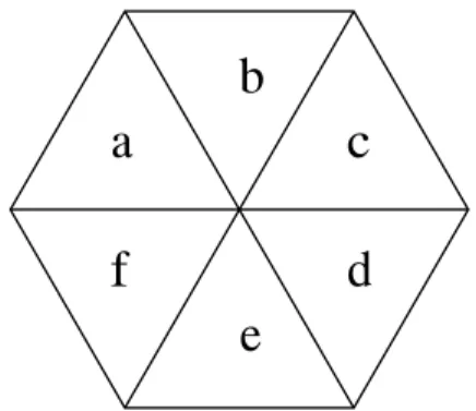
A final way to reduce the possibility of collisions would be to further subdivide the cell as illustrated in Figure 9. Each subdivision of the cell would correspond to one or more slots in the CP. When a mobile host powers on, it calculates which cell and then which subdivision it is in. It then sends it’s request in the slot in the CP corresponding to the subdivision that it is in. By increasing the number of subdivisions, we decrease the possibility of two or more mobile hosts powering on in the same subdivision and therefore reducing further the possibility of collisions in the CP. The obvious disadvantage with increasing the number of subdivisions is that the number of slots in the CP needs to be increased accordingly, therefore reducing the network throughput and increasing the time between CFPs.
3.4.5.2 Empty Cell / Mobile host powers on
By dividing access to the medium in the CFP and the CP, the most difficult task to solve is how to allocate the first mobile host in the cell a slot in the CFP. Once there
b
d
e
f
a
c
Figure 9: Subdivision of a Cell
is one mobile host in the cell with a slot in the CFP then it is possible to use the atomic broadcast protocol described in section 3.4.3 to allocate and de-allocate slots etc. A simple approach would be for a mobile host to wait for another mobile host to transmit in the CP. These two mobile hosts could then negotiate with each other in the CP to agree on an allocation of slots in the CFP. The main problem with this approach is that two mobile hosts could easily corrupt each other’s packets in the CP and therefore be unable to reach agreement. The likelihood of this occurring increases as the number of mobile hosts powering on, within the cell, increases and is also exacerbated by the fact that the CP is relatively small compared to the CFP. The possibility of reducing these collisions could be achieved by using some of the techniques described in the previous section (see 3.4.5.1).
If there is the possibility of a large number of mobile hosts powering on at the same time, then the above approach could result in every mobile host in the cell being prevented from being allocated a slot in the CFP due to collisions during transmission in the CP. A different approach would be for a mobile host to choose a number of random slots in the CFP to transmit in. This approach is similar to the previously described approach with the advantage that the CFP is typically much larger than the CP and therefore the possibility of collisions is further reduced. By allowing collisions to occur in the CFP, we are contradicting our definition of the CFP as being free of contention. However, as we shall see in the following paragraphs, the possibility of these collisions continuing to occur after a brief number of CFPs is greatly reduced.
To clarify how the new approach would work, a mobile host powers on and listens for one full CFP (CFP 1 in Figure 11) in which the mobile host does not receive any transmission, the mobile host generates a list of slots to use during the next CFP. The success of this approach depends on the way the list of slots are generated. A simple algorithm for the generation of these slots would be to use a hashing function based on the MAC address of the mobile host to generate the list of slots to use. This hashing function could also take as a parameter the subdivision of the cell that the mobile host is in.
If two or more mobile hosts power on at the same time and in the same cell, then the probability of each mobile host generating the same list of slots to use in the next CFP is very small (by virtue of the hashing function). Thus during the next CFP (CFP 2 in Figure 11), one (or more) of the transmissions from one (or more) of the mobile hosts will be received correctly by the other mobile hosts.
This is illustrated in Figure 10 where three mobile hosts, A, B and C, generate 27
a list of slots to use. All but one of the slots generated by A, B and C are corrupted due to collisions. Therefore, A, B and C hear at least one transmission of the other mobile hosts.
Figure 10: Collisions of generated slots
A naive option at this point would be for each mobile host that correctly receives a message from another mobile host to assume that the mobile host, which has successfully transmitted, has been allocated a slot and that the mobile hosts that have correctly received a message should then request a slot to be allocated to them in the next CP.
The reason that this option is naive is that may be possible for every mobile host correctly receives at least one message during the CFP (as in Figure 10). This would then result in every mobile host, that previously transmitted during the CFP, requesting a slot in the following CP because no mobile host knows if its transmis-sions have been successful or not and therefore no mobile host has been allocated a slot. In other words, every mobile host assumes that one of the other mobile hosts has been allocated a slot. This brings us back to where we were previously with no mobile host allocated a slot. Each mobile host would then have to generate another list of CFP slots and repeat the above sequence of steps.
The above deadlock problem can be solved by using the next CFP (CFP 3 in Figure 11) to transmit acknowledgments. During CFP 2, the mobile host transmits in the slots in its generated list and then listens for correct messages in each of the other slots. In the following CFP (CFP 3 in Figure 11), a mobile host transmits an Acknowledgment message, containing a Collision bitmap in the Additional Info field, in each slot in its generated list. The Collision bitmap represents CFP 2 with the position of messages, that were received by the mobile host correctly, being marked in the bitmap. By using the information in the Collision Bitmap and the Allocation Bitmap, each mobile host knows which of the messages in its various slots from CFP 2 were received correctly or were not received correctly (probably due to collisions). Therefore, at the beginning of CFP 4, each mobile host knows whether it can transmit successfully or not in each of its generated slots.
Each mobile host, that did not correctly receive an acknowledgment for any of its messages, requests a slot to be allocated to it in the next CP (CP 3 in Figure 11) according to the possible strategies described in section 3.4.5.1.
3.4.5.3 Non-empty Cell / Mobile host enters cell