reference model
M. Radimirsch, E.V. Matthiesen, G. Huszerl,
M. Reitenspieß, M. Kaˆaniche, I.E. Svinnset,
A. Casimiro, L. Falai
DI–FCUL
TR–07–18
September 2007
Departamento de Inform´atica
Faculdade de Ciˆencias da Universidade de Lisboa
Campo Grande, 1749–016 Lisboa
Portugal
Technical reports are available at http://www.di.fc.ul.pt/tech-reports. The files are stored in PDF, with the report number as filename. Alternatively, reports are available by post from the above address.
DENETS
ghly DEpendableIP-basedNETworksandServices
Wednesday, 18 October 2006 11:10 Page 1 of 89 IST-FP6-STREP-26979 / HIDENETS
Last saved by Anne Bock Public
M:\Deliverable D1.1\D1.1 WP1-Use.Case.Scenarios.v1.final.doc
Project no.:
IST-FP6-STREP- 26979
Project full title:
Highly dependable ip-based networks and services
Project Acronym:
HIDENETS
Deliverable no.:
D1.1
Title of the deliverable:
Use case scenarios and preliminary
reference model
Contractual Date of Delivery to the CEC: 30th September 2006
Actual Date of Delivery to the CEC: 29th September 2006
Organisation name of lead contractor for this deliverable Carmeq
Author(s): Markus Radimirsch, Erling V. Matthiesen, Gábor Huszerl, Manfred Reitenspieß, Mohamed
Kaâniche, Inge Einar Svinnset, António Casimiro, Lorenzo Falai
Participant(s): Marc Löbbers, Marc-Olivier Killijian, Tone Ingvaldsen, Audun Fosslie Hansen, Irene de
Bruin, Hélène Waeselynck, Nicolas Rivière
Work package contributing to the deliverable: WP1
Nature: R
Version: 1.1
Total number of pages: 89
Start date of project: 1st Jan. 2006 Duration: 36 month
Project co-funded by the European Commission within the Sixth Framework Programme (2002-2006) Dissemination Level
PU Public X
PP Restricted to other programme participants (including the Commission Services)
RE Restricted to a group specified by the consortium (including the Commission Services)
Abstract:
Keyword list: HIDENETS, dependability, communication systems, ad hoc networks, wireless, middleware
solutions, car-to-car communication, applications, use cases, business impact, preliminary reference model This document provides the starting point for the development of dependability solutions in the HIDENETS project with the following contents:
(1) A conceptual framework is defined that contains the relevant terminology, threats and general requirements. This framework is a HIDENETS relevant subset of existing state-of-the-art views in the scientific dependability community. Furthermore, the dependability framework contains a first list of relevant functionalities in the communication and middleware level, which will act as input for the architectural discussions in HIDENETS work packages (WPs) 2 and 3.
(2) A set of 17 applications with HIDENETS relevance is identified and their corresponding dependability requirements are derived. These applications belong mostly to the class of car-to-car and car-to-car-to-infrastructure services and have been selected due to their different types of dependability needs.
(3) The applications have been grouped in six HIDENETS use cases, each consisting of a set of applications. The use cases will be the basis for the development of the dependability solutions in all other WPs. Together with a description of each use-case, application-specific architectural aspects are identified and corresponding failure modes and challenges are listed.
(4) The business impact of dependability solutions for these use cases is analysed.
(5) A preliminary definition of a HIDENETS reference model is provided, which contains high-level architectural assumptions. This HIDENETS reference model will be further developed in the course of the HIDENETS projects in close cooperation with the other WPs, which is the reason why the preliminary version also contains a collection of potential contributions from other WPs that shall be developed and investigated in the course of the HIDENETS project. In summary, the identified use-cases and their requirements clearly show the large number of dependability related challenges. First steps towards technical solutions have been made in this report in the preliminary reference model, whereas the other work-packages have started in the meanwhile to develop such solutions further based on ‘middleware technology’ (WP2), ‘communication protocols’ (WP3), ‘quantitative analysis methodology’ (WP4), and ‘design and testing methodology’ (WP5).
Table of Contents
BIBLIOGRAPHY... 7 ABBREVIATIONS... 10 1. EXECUTIVE SUMMARY ... 11 2. CONCEPTUAL FRAMEWORK... 13 2.1 DEPENDABILITY FRAMEWORK... 132.1.1 Dependability related properties ... 14
2.1.2 Dependability related threats ... 15
2.1.3 Fault tolerance related requirements ... 16
2.2 COMMUNICATION LEVEL SERVICES AND PROPERTIES... 17
2.2.1 Network protocols and services ... 18
2.2.1.1 Wireless link layer protocols... 18
2.2.1.2 Routing and forwarding ... 19
2.2.1.3 Broadcast/Multicast/GeoCast... 20
2.2.1.4 Error detection and performance monitoring ... 20
2.2.1.5 Mobility management ... 20
2.2.1.6 Transport protocol... 21
2.2.1.7 Cross-layer optimisation ... 22
2.2.1.8 Session layer service and lower layer service middleware ... 22
2.2.2 Communication Properties ... 23
2.2.2.1 Throughput... 23
2.2.2.2 Communication Delay ... 23
2.2.2.3 Data integrity/packet error ratio ... 23
2.2.2.4 Packet loss... 24
2.2.2.5 Network congestion ... 24
2.3 MIDDLEWARE LEVEL SERVICES AND PROPERTIES... 24
2.3.1 Middleware Level Services ... 24
2.3.2 Middleware Level Properties... 26
3. APPLICATIONS ... 27
3.1 OVERVIEW... 27
3.2 APPLICATION DESCRIPTION... 27
3.2.1 Floating Car Data ... 27
3.2.1.1 Communication level requirements on Floating Car Data application ... 28
3.2.1.2 Middleware level requirements on Floating Car Data application... 28
3.2.1.3 General requirements on floating car data application... 29
3.2.2 Traffic sign extension... 29
3.2.2.1 Communication level requirements on Traffic Sign Extension application ... 30
3.2.2.2 Middleware level requirements on Traffic Sign Extension application... 30
3.2.3 Unusual driver behaviour warning... 30
3.2.3.1 Communication level requirements on Unusual driver behaviour warning applications . 31 3.2.3.2 Middleware level requirements on Unusual driver behaviour warning applications... 31
3.2.3.3 General requirements on Unusual driver behaviour warning applications ... 32
3.2.4 Hazard warning between vehicles ... 32
3.2.4.1 Communication level requirements on hazard warning between vehicles ... 32
3.2.4.2 Middleware level requirements on hazard warning between vehicles... 33
3.2.5 Hazard warning of the own vehicle ... 33
3.2.5.1 Communication level requirements on Hazard warning of the own vehicle application.. 33
3.2.5.2 Middleware level requirements on Hazard warning of the own vehicle applications ... 34
3.2.6.1 Communication level requirements on Platooning application ... 34
3.2.6.2 Middleware level requirements on Platooning application... 35
3.2.6.3 General requirements on Platooning application ... 35
3.2.7 Distributed black box... 36
3.2.7.1 Communication level requirements on Distributed black-box application... 37
3.2.7.2 Middleware level requirements on Distributed black-box application ... 37
3.2.7.3 General requirements on Distributed black-box application... 37
3.2.8 Maintenance and software updates ... 39
3.2.8.1 Communication level requirements on Maintenance and software updates application .. 39
3.2.8.2 Middleware level requirements on Maintenance and software updates application ... 39
3.2.8.3 General requirements on Maintenance and software updates application ... 39
3.2.9 Blackboard application ... 40
3.2.9.1 Communication level requirements on Blackboard application ... 40
3.2.9.2 Middleware level requirements on Blackboard application... 40
3.2.9.3 General requirements Blackboard application ... 41
3.2.10 Video conference ... 41
3.2.10.1 Communication level requirements on video conference application ... 41
3.2.10.2 Middleware level requirements on video conference application... 42
3.2.11 Online Gaming ... 42
3.2.11.1 Communication level requirements on online gaming application... 42
3.2.11.2 Middleware level requirements on online gaming application ... 42
3.2.12 Audio and video streaming... 43
3.2.12.1 Communication level requirements on audio and video streaming applications ... 43
3.2.12.2 Middleware level requirements on audio and video streaming application ... 44
3.2.13 Streaming data ... 44
3.2.13.1 Communication level requirements on streaming data application ... 44
3.2.13.2 Middleware level requirements on streaming data application... 45
3.2.13.3 General requirements on streaming data application ... 45
3.2.14 Non-interactive data communication and messaging ... 45
3.2.14.1 Communication level requirements on non-interactive data communication and messaging application ... 46
3.2.14.2 Middleware level requirements on non-interactive data communication and messaging application ... 46
3.2.15 Interactive data... 46
3.2.15.1 Communication level requirements on interactive data application ... 47
3.2.15.2 Middleware level requirements on interactive data application... 47
3.2.16 Mobile mission control centre ... 47
3.2.16.1 Communication level requirements ... 48
3.2.16.2 Middleware level requirements... 48
3.2.16.3 General requirements ... 48
3.2.17 Ad-hoc service providers... 48
3.2.17.1 Communication level requirements ... 49
3.2.17.2 Middleware level requirements... 49
3.2.17.3 General requirements ... 50
4. USE CASES ... 51
4.1 PLATOONING USE CASE... 51
4.1.1 Selected Application(s) ... 51
4.1.2 Actors and their roles ... 51
4.1.3 Challenges and failure modes ... 51
4.2 INFOTAINMENT AND WORK WITH HIGHLY MOBILE TERMINALS... 52
4.2.1 Selected application(s): ... 53
4.2.2 Actors and their roles: ... 53
4.3 CAR ACCIDENT (INCL DISTRIBUTED BLACK-BOX)... 54
4.3.1 Selected application(s): ... 55
4.3.2 Actors and their roles: ... 56
4.3.3 Failure modes, challenges and subjects for further investigation ... 56
4.4 ASSISTED TRANSPORTATION... 58
4.4.1 Selected application(s): ... 58
4.4.2 Actors and their roles: ... 59
4.4.3 Challenges ... 60
4.5 BRIGADE COMMUNICATION... 61
4.5.1 Selected application(s)... 61
4.5.2 Actors and their roles ... 61
4.5.3 Challenges ... 61
4.6 SERVICE DISCOVERY IN AD-HOC NETWORKS... 62
4.6.1 Selected application(s)... 62
4.6.2 Actors and their roles ... 62
4.6.3 Challenges ... 62
5. BUSINESS IMPACT ANALYSIS... 64
5.1 RELATED WORK ON BUSINESS ANALYSIS AND DEPENDABILITY FOR CAR-TO-CAR COMMUNICATION SYSTEMS... 64
5.2 BUSINESS EFFECT OF THE INTRODUCTION OF MORE DEPENDABLE SERVICES... 64
5.3 BUSINESS IMPACT ANALYSIS OF USE CASES... 65
5.3.1 Platooning use case – business impact... 65
5.3.1.1 Platooning use case – Alternative technologies ... 65
5.3.1.2 Platooning use case – costs and benefits... 66
5.3.2 Infotainment and work with highly mobile terminals use case – business impact ... 66
5.3.2.1 Infotainment and work with highly mobile terminals use case – Alternative technologies 67 5.3.2.2 Infotainment and work with highly mobile terminals use case – costs and benefits ... 67
5.3.3 Car accident use case – business impact... 67
5.3.3.1 Car accident use case – Alternative technologies ... 68
5.3.3.2 Car accident use case – costs and benefits ... 68
5.3.4 Assisted transportation use case – business impact ... 69
5.3.4.1 Assisted transportation use case – Alternative technologies... 69
5.3.4.2 Assisted transportation use case – costs and benefits ... 69
5.3.5 Brigade communication use case – business impact ... 70
5.3.5.1 Brigade communication use case – Alternative technologies ... 70
5.3.5.2 Brigade communication use case – costs and benefits... 70
5.3.6 Broadcasting use case – business impact ... 71
5.3.6.1 Broadcasting use case – Alternative technologies ... 71
5.3.6.2 Broadcasting use case – costs and benefits ... 71
6. PRELIMINARY REFERENCE MODEL... 73
6.1 REFERENCE MODEL GENERAL PART... 73
6.2 REFERENCE MODEL: EXPECTED RESULTS FROM WP2–RESILIENT ARCHITECTURE AND MIDDLEWARE... 75
6.2.1 Conceptual models for the design of middleware services ... 75
6.2.2 Expected results ... 77
6.3 REFERENCE MODEL – EXPECTED RESULTS FROM WP3–RESILIENT COMMUNICATION... 78
6.3.1 Expected results from WP3... 79
6.4 REFERENCE MODEL – EXPECTED RESULTS FROM WP4–QUANTITATIVE EVALUATION... 80
6.4.1 The HIDENETS holistic approach to quantitative evaluation ... 81
6.4.2 Expected results from WP4... 82
6.5 REFERENCE MODEL – EXPECTED RESULTS FROM WP5-DESIGN METHODOLOGIES AND TESTING82 6.5.1 WP5 – Modelling and model based development ... 82
6.5.1.1 The Hidenets modelling approach ... 83
6.5.1.2 WP5 Design methodology - Expected results... 83
6.5.2 WP5 -Testing methodology... 83
6.5.2.1 Challenging issues in testing mobile computing systems ... 83
6.5.2.2 Perspectives and expected results for testing ... 85
6.5.2.3 Test strategy ... 85
7. OUTLOOK ... 86
A ANNEX: OPERATING CONTEXTS... 87
A.1 KIND OF ROAD... 87
A.2 ROAD TRAFFIC DENSITY... 87
A.3 EQUIPMENT RATIO... 87
A.4 COMMUNICATION PARTNER / INVOLVED NETWORK DOMAINS... 88
B ANNEX: APPLICATIONS WHICH HAVE BEEN IDENTIFIED BUT WHICH DO NOT OCCUR IN USE CASES ... 88
B.1 TOLLING... 88
B.2 PARKING GUIDE... 88
B.3 FRIEND FINDER... 89
Bibliography
[1] CAMP - Vehicle Safety Communications Project, „Task 3: Identify Intelligent Vehicle Safety Applications Enabled by DSRC - Interim Report – Jan. 2003
[2] C2CC APP, List of applications (BMW, DaimlerChrysler, Volkswagen), NOW project (in German) [3] Enkelmann W. FleetNet Applications for Inter-Vehicle Communication IEEE Intelligent Vehicles
Symposium (IV 2003), pp. 162-167, Columbus, OH, USA, June 2003 (to be found at
http://www.et2.tu-harburg.de/fleetnet/english/documents.html)
[4] Wischhof L., Ebner A., Rohling H., Lott M., Halfmann R. SOTIS - A Self-Organizing Traffic Information System 57th IEEE Semiannual Vehicular Technology Conference VTC 2003-Spring, Jeju, South Korea, April 2003 (to be found at http://www.et2.tu-harburg.de/fleetnet/english/documents.html)
[5] A. Avizienis, J.C. Laprie, "Dependable computing: from concepts to design diversity", Proceedings of the IEEE, vol. 74, no. 5, May 1986, pp. 629-638.
[6] A. Avizienis, J.C. Laprie, B. Randell, C. Landwer, "Basic Concepts and Taxonomy of Dependable and Secure Computing ", IEEE Transactions on Dependable and Secure Computing, vol. 1, no. 1, January-March 2004, pp. 11-33.
[7] W.C. Carter, "A time for reflection", in Proc. 12th IEEE Int. Symp. on Fault Tolerant Computing (FTCS-12), Santa Monica, California, June 1982, p. 41.
[8] J.C. Laprie, A. Costes, "Dependability: a unifying concept for reliable computing", Proc. 12th IEEE Int. Symp. on Fault Tolerant Computing (FTCS-12), Santa Monica, California, June 1982, pp. 18-21. [9] J.C. Laprie (Ed.), Dependability: Basic Concepts and Terminology, Springer-Verlag, Vienna, 1992. [10] IEEE 802.11 WG, “Part 11: Wireless LAN Medium Access Control (MAC) and Physical Layer (PHY)
specification”, IEEE 1999.
[11] IEEE 802.11 WG, “Draft Supplement to Part 11: Wireless Medium Access Control (MAC) and physical layer (PHY) specifications: Medium Access Control (MAC) Enhancements for Quality of Service (QoS)”, IEEE 802.11e/D13.0, Jan. 2005.
[12] Moy, J. OSPF Version 2. IETF RFC 2328 (STD 54), April 1998.
[13] Callon R W. Use of OSI IS-IS for routing in TCP/IP and dual environments. IETF RFC 1195, December 1990
[14] Rekhter, Y. A Border Gateway Protocol 4 (BGP-4). IETF RFC 4271, January 2006.
[15] Clausen T, Jacquet P. Optimized Link State Routing Protocol (OLSR). IETF RFC 3626, October 2003 [16] Spagnolo P et al. OSPFv2 Wireless Interface Type. Internet draft
‘draft-spagnolo-manet-ospf-wireless-interface-01, May 2004.
[17] Chandra M. Extensions to OSPF to Support Mobile Ad Hoc Networking. Internet draft ‘draft-chandra-ospf-manet-ext-02’, October 2004.
[18] Perkins C, Belding-Royer E, Das S. Ad hoc On-Demand Distance Vector (AODV) Routing. IETF RFC 3561, July 2003
[19] Mauve M., Widmer J., Hartenstein H. A Survey on Position-Based Routing in Mobile Ad-Hoc Networks IEEE Network, 5(6), pp. 30--39, November 2001
[20] K. Matheus, R. Morich, et al., „Car-to-Car Communication - Market Introduction and Success Factors“, ITS 2005: 5th European Congress and Exhibition on Intelligent Transport Systems and Services, 1 - 3 June 2005, Hannover, Germany
[21] K. Matheus, R. Morich, A. Lübke, „Economic Background of Car-to-Car Communications“, IMA 2004, Informationssysteme für mobile Anwendungen, 20.-21.10.2004, Braunschweig, Germany [22] A. Autenrieth, A. Kirstädter “Fault Tolerance and Resilience Issues in IP-Based Networks”, Second
International Workshop on the Design of Reliable Communication Networks (DRCN2000), Munich, Germany, April 9-12, 2000
[23] T. Chandra, S. Toueg. Unreliable failure detectors for reliable distributed systems. Journal of the ACM, 43(2):225–267, March 1996.
[24] E. Perera, V. Sivaraman, and A. Seneviratne, "Survey on Network Mobility Support", ACM SIGMOBILE Mobile Computing and Communications Review, 8(2):7-19, Apr 2004.
[25] X.Y. Li and I. Stojmenovic,Broadcasting and topology control in wireless ad hoc networks, in Handbook of Algorithms for Mobile and Wireless Networking and Computing, (A. Boukerche and I. Chlamtac, eds.), CRC Press, to appear.
[26] X. Chen and J. Wu, Multicasting techniques in mobile ad hoc networks, in The handbook of ad hoc wireless networks, CRC presss. Pages 25-40, 2003.
[27] I. Stojmenovic, Geocasting in ad hoc and sensor networks, in Theoretical and Algorithmic Aspects of Sensor, Ad Hoc Wireless and Peer-to-Peer Networks (Jie Wu, ed.), Auerbach Publications (Taylor & Francis Group), 2006, 79-97.
[28] ITU-T Recommendation X.200 (1994) | ISO/IEC 7498-1:1994, Information technology – Open Systems Interconnection – Basic Reference Model: The Basic Model (and corresponding references therein)
[29] ITU-T Rec. X.901 | ISO/IEC 10746-1: Information technology — Open Distributed Processing — Reference model: Overview (and corresponding references therein)
[30] Boris Beizer. Software Testing Techniques. Van Nostrand Reinhold, 2nd edition, 1990 [31] T.H. Tse, Stephan S. Yau, W.K. Chan, Heng Lu. Testing Context-Sensitive Middleware-Based
Software Applications, Proceedings of the 28th Annual International Computer Software and Application Conference (COMPSAC 2004), pp.458-466, IEEE CS Press, 2004.
[32] Satyajit Achrya, Chris George, Hrushikesha Mohanty. Specifying a Mobile Computing Infrastructure and Services, 1st International Conference on Distributed Computing and Internet Technology (ICDCIT 2004), LNCS 3347, pp.244-254, Springer-Verlag Berlin Heidelberg, 2004
[33] Satyajit Acharya, Hrushikesha Mohanty, R.K Shyamasundar. MOBICHARTS: A Notation to Specify Mobile Computing Applications. Proceedings of the 36th Hawaii International Conference on System Sciences (HICSS’03), IEEE CS Press, 2003.
[34] Vincenzo Grassi, Raffaela Mirandola, Antonino Sabetta. A UML Profile to Model Mobile System, UML 2004,
[35] Hubert Baumeister et al. UML for Global Computing. Global Computing: Programming
Environments, Languages, Security, and Analyisis of Systems, GC 2003, LNCS 2874, pp. 1-24, Springer-Verlag Berlin Heidelberg, 2003
[36] W.K. Chan, T.Y. Chen, Heng Lu. A Metamorphic Approach to Integration Testing of
Context-Sensitive Middleware-Based Applications, Proceedings of the 5th International Conference on Quality Software (QSIC’05), pp.241-249, IEEE CS Press, 2005
[37] Karl R.P.H Leung, Joseph K-Y Ng, W.L. Yeung. Embedded Program Testing in Untestable Mobile Environment: An Experience of Trustworthiness Approach, Proceedings of the 11th Asia-Pacific Software Engineering Conference, pp.430-437, IEEE CS Press, 2004
[38] de Bruin, D.; Kroon, J.; van Klaverem, R.: Nelisse, M.. Design and test of a cooperative adaptive cruize control system, Intelligent Vehicles symposium, pp.392-396, IEEE CS Press, 2004
[39] Christoph Schroth et al. Simulating the traffic effects of vehicle-to-vehicle messaging systems, Proceedings of ITS Telecommunication, 2005
[40] Ricardo Morla, Nigel Davies. Evaluating a Location-Based Application: A Hybrid Test and Simulation Environment, IEEE Pervasive computing, Vol.3, No.2, pp.48-56, July-September 2004
[41] J.Barton, V. Vijayaragharan. Ubiwize: A Simulator for Ubiquitous Computing Systems Design, Technical report HPL-2003-93, Hewlett-Packard Labs, 2003
[42] Kumaresan Sanmiglingam, Geogre Coulouris. A Generic Location Event Simulator, UbiComp 2002, LNCS 2498, pp.308-315, Springer-Verlag Berlin Heidelberg, 2002
[43] P. Thévenod-Fosse, H. Waeselynck and Y. Crouzet, “Software statistical testing”, in Predictably Dependable Computing Systems, Springer Verlag, pp. 253-272, 1995
[44] C. Perkins, “IP Mobility Support for Ipv4”, IETF RFC 3344, August 2002 [45] J. Rosenberg, et al., “Session Initiation Protocol”, IETF RFC 3261, June 2002
[46] R. Stewart, et al., “Stream Control Transmission Protocol”, IETF RFC 2960, Oct. 2000
[47] Flaviu Cristian, Christof Fetzer. The timed asynchronous system model. In Proceedings of the 28th Annual International Symposium on Fault-Tolerant Computing, pp.140-149, Munich, Germany, June 1998. IEEE CS Press.
[48] Paulo Veríssimo, António Casimiro. The timely computing base model and architecture. IEEE Transactions on Computers, 51(8):916–930, 2002.
[49] P. Veríssimo and L. Rodrigues. Distributed Systems for System Architects. Kluwer Academic Publishers, 2001.
Abbreviations
AC Access Control
C2CC Car-to-Car Communication CAC Connection Admission Control DFCD Decentralized Floating Car Data
DSRC Dedicated Short Range Communication FCD Floating Car Data
HWI Hazard warning and information from other vehicles IAM Internet access on the move
IP Internet Protocol HC Handover Control HLR Home Location Register LAN Local Area Network
LC Load Control
MSU Maintenance and Software Updates
PC Power Control
PS Packet Scheduler QoS Quality of Service
RDS Radio Data System (broadcasts e.g. radio station name for displaying) RM Reference Model
RRM Radio Resource Management
RTC Interactive real-time communication between cars/terminals
SIP Session Initiation Protocol (used in 3.2.1.8 when describing session control) TFC Traffic Flow Control
TMC Traffic Message Channel (inside RDS) TSE Traffic Sign Extension
VLR Visiting Location Register WLAN Wireless LAN
1. Executive Summary
Overall objectives of WP1 & context of this deliverable:
This deliverable contributes to the HIDENETS main objectives, which are stated in the Technical Annex:
“HIDENETS addresses the provision of available and resilient distributed applications and mobile services with critical requirements on highly dynamic and possibly unreliable open communication infrastructures.”
WP 1 contributes to this overall objective with its activities and takes on an umbrella function. WP1 shall set the framework of the project at its beginning and summarize its results in the end. The WP 1 objectives, as stated in the Technical Annex, are:
“The aim of this WP is to identify a set of use case scenarios that, on the one hand will exemplify those application areas that will benefit from the technology that will be developed in HIDENETS, and on the other hand, serve as a source of requirements and technical challenges to be addressed by the project. This WP will be based on joint work with the contributions of all project partners.
Based on the analysis of the application scenarios, a reference model will be defined to specify the needs and requirements that will be addressed by the design and validation activities to be carried within WP2, WP3, WP4, WP5 and WP6. During the course of the project, the reference model will be refined as a result of feedback from these work packages. At the end of the project, the main lessons learned from all the activities carried out during the project with respect to the deployment and validation of dependable and resilient applications in HIDENETS scenarios will be consolidated and guidelines will be provided to help potential users (telecommunication operators, automotive industry, end-users) to utilize the technology and methods developed in the project.”
The WP1 activities have started at the beginning of the HIDENETS project and cover the full 3-year duration of the project. This deliverable documents initial results, namely the applications and use-cases, which are finalized (except for smaller on-demand refinements) as well as intermediate results for work-in progress. The latter refers to the preliminary reference model and the business impact analysis. Both the finalized and intermediate results are important input for all other WPs for the development of the HIDENETS solutions.
Summary of the content of the deliverable:
This deliverable represents the results from the starting phase of HIDENETS. Its task is to identify a relevant set of applications, to summarize them in use cases and to represent a preliminary description of the HIDENETS reference model. Since the overall goal of HIDENETS is to develop end-to-end dependability solutions, Section 2 develops a conceptual framework, starting with a dependability framework. This dependability framework contains the relevant terminology, dependability threats, and general requirements and is built upon a HIDENETS-relevant subset of existing state-of-the-art views in the scientific dependability community. Furthermore, the dependability framework contains a first list of relevant functionalities, both for communication and middleware services, which will act as input for the architectural discussions in WPs 2 and 3.
The dependability solutions that will be developed in HIDENETS will be of general applicability, but in order to guide their development, a set of applications and use-cases has been selected, mostly from the field of car-to-car and car-to-infrastructure communications. This is motivated by the fact that this class of applications optimally represents the overall scenario of HIDENETS, i.e. highly dynamic ad hoc networking together with challenging issues in the fixed network domain. The set of in total 17 applications covers a wide range of dependability requirements, from infotainment-type applications with less strict dependability requirements to safety-critical and very real-time dependent applications like platooning. These applications together with their requirements on service-level middleware and on network communication are listed in Section 3. The requirements are derived from the HIDENETS perspective, i.e. in relation to the dependability framework in Sect. 2.
Certain subsets of these applications have been grouped in six HIDENETS use-cases, which will be the basis for the development of the dependability solutions in all other work-packages. These use-cases are: Platooning, Infotainment, Car Accident, Assisted Transportation, Brigade Communication, and Ad-hoc Service Discovery. After a description of each use-case, application-specific architectural aspects are identified, including the main functional entities (actors) and their roles. As an outcome of the analysis of different failure modes, challenges for the dependability solutions are identified. These use cases represent a framework for more detailed investigations in subsequent HIDENETS WPs. This does not necessarily imply that all use cases with all their applications will be covered by subsequent WPs. Rather, the WPs following WP1 will make a selection of use cases and applications that will be further investigated.
The business analysis part creates a relation between the technical description and the economical effects of the HIDENETS project. It is a starting point, though, and WP1 intends to further refine it in the course of the project.
Finally, this document contains a preliminary reference model in Section 6, by summarizing high-level architectural assumptions for the HIDENETS solutions in addition to the already described dependability framework in Sect 2. This HIDENETS reference model will be further developed subsequently in close cooperation with the other Work-packages. Therefore, the preliminary version also contains a description of envisioned contributions from other WPs to be investigated further in the future. The final reference model will be an important outcome of HIDENETS. It will summarize all results obtained in the project in a generalized and abstract manner, such that subsequent projects and developments in the field can use it as a guideline for their work.
In summary, the identified use-cases and their requirements clearly show the large number of dependability related challenges. First steps towards technical solutions have been made in this report in the preliminary reference model, while the other work-packages have started in the meanwhile to develop such solutions further based on ‘middleware technology’ (WP2), ‘communication protocols’ (WP3), ‘quantitative analysis methodology’ (WP4), and design and testing methodology (WP5).
2. Conceptual framework
This section introduces some basic concepts that will be used in this document to characterize the applications relevant to Hidenets. The concepts cover three main perspectives: 1) the dependability framework defines the properties, the threats, and the fault tolerance related requirements; 2) the communication level services and requirements introduce some relevant concepts covering the communication and networking layers, and 3) the middleware level services and properties introduce potential relevant services to Hidenets applications, that can be deployed at the middleware layer to fulfill the dependability requirements of the applications.
2.1 Dependability Framework
Before describing the main issues to be addressed in the specification of dependability related requirements, it is important to give precise definitions of the concepts and terminology used in this document. The definitions presented in the following are based on the dependability concepts that have been developed and updated since the mid-seventies by the Fault-Tolerant Computing community, and especially the IFIP Working Group 10.4, [5] [6] [7] [8] [9]. It is noteworthy that other concepts similar to dependability exist, such as survivability, trustworthiness and resilience (see e.g. [6] for a definition of some of these concepts and a comparison with dependability).
Dependability is the ability to deliver service that can justifiably be trusted. The service delivered by a
system (in its role as a service provider) is its behaviour as perceived by its user(s). The function of a system is what the system is intended to do and is described by the functional specification in terms of functionality and performance. Correct service is delivered when the service implements the system function. A service
failure occurs when the delivered service deviates from correct service. A failure is thus a transition from
correct service to incorrect service. The period of delivery of incorrect service is a service outage. The transition from incorrect service to correct service is a service restoration. Based on the definition of failure, an alternate definition of dependability, which complements the initial definition in providing a criterion for deciding if the service is dependable, is as follows: the ability of a system to avoid service failures that are more frequent and more severe than is acceptable.
A systematic exposition of dependability consists of three main parts: the threats to, the attributes of and the
means by which dependability is attained. The dependability threats correspond to faults, errors and failures
that might affect the service(s) delivered by the system. The dependability attributes define the main facets of dependability that are relevant for the target system and applications. The dependability means correspond to the methods and techniques used to support the production of a dependable system. These means can be classified into four major categories:
• fault prevention: to prevent the occurrence or introduction of faults, • fault tolerance: to avoid service failures in the presence of faults, • fault removal: to reduce the number and severity of faults,
• fault forecasting: to estimate the present number, the future incidence, and the likely consequences of faults.
Fault prevention and fault tolerance aim to provide the ability to deliver a service that can be trusted, while fault removal and fault forecasting aim to reach confidence in this ability by justifying that the functional and the dependability and security specifications are adequate and that the system is likely to meet them.
Fault prevention is part of general engineering and can be attained through the use of rigorous development techniques, high-level specification and design methodologies, structured programming, information hiding, modularization, etc.
Fault tolerance which is aimed at failure avoidance is generally implemented by error detection and subsequent system recovery. More details about these techniques are provided in section 2.1.3.
Fault removal is performed both during the development phase and the operational life of a system. During the development, it consists of three steps: verification, diagnosis, and correction. Verification is the process of checking whether the system adheres to given properties, termed the verification conditions. If does not, the other two steps are applied. Verification activities are generally implemented using a combination of static analysis, model checking, theorem proving, testing, etc.
Finally, fault forecasting is conducted by performing an evaluation of the system behaviour with respect to fault occurrence or activation. Evaluation has two aspects: a) qualitative, or ordinal evaluation which aims to identify, classify and rank the failure modes or the combinations of event that would lead to system failures, and b) quantitative, or probabilistic, evaluation, which aims to evaluate in terms of probabilities the extent to which some of the attributes of dependability are satisfied; those attributes are then viewed as measures of dependability. Various methods can be used to support these evaluations, including analytical modelling, simulation, experimental measurements as well as judgements.
The solutions investigated in the Hidenets project cover various dimensions of dependability taking into account the four classes of dependability means (fault prevention, fault tolerance, fault removal, and fault forecasting). The development of these solutions will be based on the analysis of the specific requirements and challenges characterizing various applications and use case scenarios presented in the following sections. Based on the concepts defined above, three main parts should be considered for the specification of
dependability related requirements characterizing the different use cases and applications that are relevant to
Hidenets:
• Properties: to specify the desired dependability attributes
• Threats: to describe the list of faults and failures that might affect the service(s) delivered by the applications and systems under study in case these are not addressed properly.
• Fault Tolerance: to specify the error detection and recovery strategies to be implemented to cope with the dependability threats in order to satisfy the targeted dependability properties.
Besides fault tolerance requirements, it is noteworthy that the other dependability means are equally important and should be addressed carefully. As regards the fault forecasting process, the specification of the dependability threats and dependability properties can be considered as a part of this process. Concerning the fault prevention and fault removal processes, we don’t think that specific requirements need to be specified and described for each application or use case considered in the following. A more general discussion about the challenges and solutions explored with respect to fault prevention and fault removal, considering in particular design methodologies and testing, are discussed in section 7.5 in the context of the Hidenets reference model.
A brief description of the main issues to be addressed for the specification of the dependability properties, threats, and fault tolerance related requirements are described in the following three subsections.
2.1.1 Dependability related properties
Depending on the applications considered, different facets of dependability may be important, i.e., different emphasis may be put on different attributes of dependability. Basic dependability attributes are defined as follows:
• availability: readiness for correct service • reliability: continuity for correct service
• safety: absence of catastrophic consequences on the user(s) and the environment • confidentiality: absence of unauthorized disclosure of information
• maintainability: ability to undergo modifications and repairs
Several other dependability attributes can be obtained as combinations or specialization of the primary attributes listed above. In particular, security is defined as the concurrent existence of a) availability for authorised users only, b) confidentiality and c) integrity where ‘improper’ means ‘unauthorised’.
The attributes of dependability may be emphasised to a greater or a lesser extent depending on the application: availability, integrity and maintainability are generally required, although to a varying degree depending on the application, whereas reliability, safety and confidentiality may or may not be required. The extent to which a system possesses the attributes of dependability should be considered in a relative, probabilistic sense, and not in an absolute, deterministic sense. Due to the unavoidable presence or occurrence of faults, systems are never totally available, reliable, safe or secure.
Integrity is a prerequisite for availability, reliability and safety, but may not be so for confidentiality (for instance, attacks via covert channels or passive listening can lead to a loss of confidentiality, without impairing integrity). The definition given above for integrity — absence of improper system alterations extends the usual definition as follows: (a) when a system implements an authorisation policy, ‘improper’ encompasses ‘unauthorised’; (b) ‘improper alterations’ encompass actions that prevent (correct) upgrades of information; (c) ‘system state’ encompasses hardware modifications or damages.
Besides the attributes listed above, other secondary attributes can be considered to refine the primary attributes. An example of such a secondary attribute is robustness, i.e., dependability with respect to external faults, which characterises a system’s reaction to a specific class of faults.
The notion of secondary attributes is especially relevant for security, when we distinguish among various types of information. Examples of such secondary attributes are:
• accountability: availability and integrity of the identity of the person who performed an operation
• authenticity: integrity of a message content and origin, and possibly of some other information, such as the time of emission.
• nonrepudiability: availability and integrity of the identity of the sender of a message (nonrepudiation of the origin), or the receiver (nonrepudidation of reception)
Variations in the emphasis on the different attributes of dependability directly affect the appropriate balance of the techniques (fault prevention, tolerance, removal, forecasting) to be employed in order to make the resulting systems dependable. This problem is all the more difficult as some attributes conflict (e.g., availability and safety, availability and security), necessitating design trade-offs.
2.1.2 Dependability related threats
The dependability threats mainly correspond to the faults, errors, and failures that should be covered by the target applications to satisfy the desired dependability properties.
A service may fail either because it does not comply with the functional specification, or because this specification did not adequately describe the system function. A service failure occurs when at least one or more external state(s) of the system deviate from the correct service state. The deviation is called an error. The adjudged or hypothesized cause of an error is called a fault.
A system may not, and generally does not, always fail in the same way. The ways a system can fail are its
failure modes, which may be characterised according to four viewpoints:
• the failure domain which leads to the distinction of content failures (e.g. incorrect values), timing
failures (e.g. service delivered too early or too late).
• the detectability of failures which addresses the signalling of the service failures to the users,
• the consistency of failures when two or more service users are involved leading to the distinction of
consistent failures (when the incorrect service is perceived identically by all the users) from inconsistent failures, usually called byzantine failures, (when some or all users perceive differently incorrect service)
• the consequences of failures on the environment which leads to the grading of failure modes according to different failure severities.
When designing a dependable system, it is very important to identify which fault classes are to be taken into account because different means are to be used to deal with different fault classes. Thus, fault assumptions influence directly the design choices, and also the level of dependability that can be achieved.
Faults and their sources are very diverse. They can be classified according to different criteria: the phase of creation (development vs. operational faults), the system boundaries (internal vs. external faults), their phenomenological cause (natural vs. human-made faults), the dimension (hardware vs. software faults), the persistence (permanent vs. transient faults), the objective of the developer or the humans interacting with the system (malicious vs. nonmalicious faults), their intent (deliberate vs. non-deliberate faults), or their capability (accidental vs. incompetence faults).
Malicious faults are human-made faults that are generally introduced with the malicious objective to alter the functioning of the system during use. The goals of such faults are: 1) to disrupt or halt service, causing denials of service; 2) to access confidential information; or 3) to improperly modify the system. They can be grouped into two classes: 1) malicious logic faults that encompass faults introduced during the development phase such as Trojan horses, logic or timing bombs, and trapdoors, as well as operational faults such as viruses, worms or zombies (see e.g. [6] for a precise definition of these terms); and 2) intrusion attempts that are operational external faults. The external character of intrusion attempts does not exclude the possibility that they may be performed by system operators or administrators who are exceeding their rights.
The list of failures and faults assumptions to be addressed in the development process should be completed by the specification of the acceptable degraded operation modes as well as of the constraints imposed on each mode, i.e., the maximal tolerable service interruption duration and the number of consecutive and simultaneous failures to be tolerated, before moving to the next degraded operation mode. The analysis of the impact of the simultaneous loss or degradation of multiple functions and services requires particular attention. Depending on the dependability needs and the system failure consequences on the environment, the need to handle more than one nearly concurrent failure modes could be vital. Such an analysis is particularly useful for the specification of the minimal level of fault tolerance that must be provided by the system to satisfy the dependability objectives. It also provides preliminary information for the minimal separation between critical functions that is needed to limit their interactions and prevent common mode failures.
2.1.3 Fault tolerance related requirements
Fault tolerance is aimed at failure avoidance. It is generally implemented by error detection and subsequent
system recovery (or simply recovery).
There exist two classes of error detection techniques:
• concurrent error detection which takes place during service delivery
• preemptive error detection which takes place while service delivery is suspended; it checks the system for latent errors (i.e., that are not yet detected) and dormant faults (i.e., that are not yet activated).
Recovery transforms a system state that contains one or more errors (and possibly faults) into a state without detected errors and faults that can be activated again. Recovery consists of error handling and fault handling.
Error handling eliminates errors from the system state. It may take three forms:
• rollback, where the state transformation consists of returning the system back to a saved state that existed prior to error detection; that saved state is a checkpoint,
• compensation, where the erroneous state contains enough redundancy to enable error elimination, • rollforward, where the state without detected errors is a new state.
• fault diagnosis, which identifies and records the cause(s) of error(s) in terms of both location and type, • fault isolation, which performs physical or logical exclusion of the faulty components from further
participation in service delivery,
• system reconfiguration, which either switches in spare components or reassigns tasks among non-failed components,
• system reinitialization, which checks, updates and records the new configuration and updates system tables and records,
Usually, fault handling is followed by corrective maintenance that removes faults isolated by fault handling. Systematic usage of compensation may allow recovery without error detection. This form of recovery is called fault masking. However, such simple masking will conceal a possibly progressive and eventually fatal loss of protective redundancy; thus practical implementations of masking generally involve error detection (and possibly fault handling), leading to masking and recovery.
The choice of error detection, error handling and fault handling techniques, and of their implementation is directly related to and strongly dependent upon the fault assumptions. The classes of faults that can actually be tolerated depend on the fault assumptions considered in the development process. Various techniques for achieving fault tolerance can be used such as performing multiple computations in multiple channels, either sequentially or concurrently, where the channels may be of identical design (if the objective is to tolerate independent physical faults or elusive design faults) or may implement the same function via separate designs and implementations, i.e. through design diversity, (if the objective is to tolerate solide design faults). Other techniques include the use of self-checking components which provide the ability to define error confinement areas.
Fault tolerance is a recursive concept: it is essential that the mechanisms that implement fault tolerance should be protected against the faults that might affect them. Examples of such protection are voter replication, self-checking checkers, stable memory for recovery programs and data.
Systematic introduction of fault tolerance is often facilitated by the addition of support systems specialized for fault tolerance (e.g., software monitors, service processors, dedicated communication links).
Fault tolerance is not restricted to accidental faults. Some mechanisms of error detection are directed towards both malicious and non-malicious faults (e.g., memory access protection techniques) and schemes have been proposed for the tolerance of both intrusions and physical faults, via information fragmentation and dispersal, as well as for tolerance of malicious logic, and more specifically of viruses, either via control flow checking, or via design diversity. It is noteworthy that the extension and adaptation to security of traditional techniques for tolerating accidental faults, led to the emergence of the intrusion tolerance concept. The focus of intrusion tolerance is on ensuring that systems will remain operational (possibly in a degraded mode) and continue to provide core services despite faults due to intrusions.
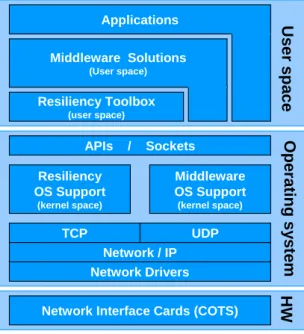
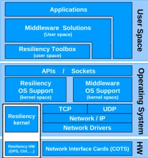
2.2 Communication level services and properties
The HIDENETS solutions will include functionality both on communication level as well as service-middleware. As indicated in the reference model in section 6, these two blocks will be architecturally separated but still closely coupled via well-defined interfaces, which will be developed in detail in WPs 2 and 3.
As a starting point for the development of the reference model and for the development of the detailed HIDENETS architecture in WPs 2 and 3, this section provides a first list of relevant functionalities for the communication level; the corresponding middleware functionalities are described in Sect 2.3.
The communication functions as defined here consist of the OSI layers 2-4 (link, network, and transport layers), as well as partly layer 5 (session layer). It is assumed that IP is used at the network layer, while several protocols, including TCP and UDP, may be used at the OSI transport layer. At the underlying link
layer, IEEE WLANs in infrastructure and ad-hoc modes, as well as traditional mobile networks like UMTS and GPRS will be used.
The communication-level requirements depend on requirements from the applications and middleware. Actual quantification of communication-level requirements will depend on the use case as well since the same application may pose different requirements based on the setting where it is used. In general, the communication functions transport chunks of information from one network node to another. Basically what the middleware does is to abstract some details of the underlying layers for the application running on top. This chapter describes a set of common communication-level services that may help to provide important dependability properties. It also lists some communication-level properties. These may represent a measure for the behaviour of the services.
2.2.1 Network protocols and services
2.2.1.1 Wireless link layer protocols
In general, link layer protocols in wireless networks control access to the shared radio medium. There is however great differences between the goal and strategy of such protocols in licence-based mobile networks like UMTS/GPRS/GSM, and licence-free wireless networks like WLANs.
UMTS/GSM/GPRS networks exercise strict, centralized control over the radio resource. The goal is to ensure the QoS agreed upon during session setup and reject sessions when resources can no longer be guaranteed. Radio Resource Management (RRM) is a well-defined concept that aims to guarantee the agreed QoS, maintain the planned coverage area, and offer a high overall system capacity. The following functions are included:
• Admission control (AC) handles all new incoming traffic and checks if a new connection can be admitted to the system. AC is based on the resource and QoS requirements of the individual connections, and the available resources of the system. AC is also involved during handovers and connection modifications. • Load control (LC) is used to avoid that the system load gets too high with the consequence that the
system breaks down. When the load exceeds a given threshold, actions are taken to reduce the load. • The Packet Scheduler (PS) divides the air transmission time between the active connections according to
the resources that have been reserved for the individual connections.
• Handover Control (HC). When a connection is handed over from one access point to another is handled by the handover control.
• Power Control (PC) maintains the radio link quality and controls the power used.
In 802.11 WLANs [10], the goal is to maximise the network utilization regardless of the number of transmitting terminals, while giving each terminal a fair share of the available bandwidth. Radio resource management is inherent in the media access protocol, and only offers loose control over the radio resource. The original WLAN standards provide a best effort service, and when the offered traffic load is too high, the overall network performance drops. The new WLAN standard 802.11e [11] will provide functions for differentiated (not guaranteed) QoS, and some control over the radio resource can be obtained by fine-tuning these WLAN parameters.
802.11 WLANs may operate in infrastructure mode or in ad-hoc mode. In infrastructure mode the terminals connect to an access point and all communication between the terminals are transmitted via the access point. Several WLANs in infrastructure mode may be grouped to construct larger infrastructure networks. WLANs in infrastructure mode are normally connected to wired infrastructure in that the access points often have a wired interface in addition to the wireless one and forward traffic between the two domains.
In ad-hoc mode, the terminals that are within mutual communication range of each other via the wireless medium communicate directly with each other (without using an access point). WLANs in ad-hoc mode can be connected to wired networks using network layer protocols outside of the WLAN standard, like for
instance Internet Protocol (IP). If for instance one of the terminals is configured as a router and has a wired interface in addition to the wireless ad-hoc interface, it may forward network layer packets between the wireless and the wired domains. The term ad-hoc network is normally used to denote wireless networks in ad-hoc mode with all terminals configured as routers. In such cases network layer routing protocols are used between the terminals to compute the best paths. These protocols are further described in section 2.2.1.2. The 802.11s extension to IEEE 802.11 provides features for mesh networking. Here, the ad hoc functionality with routing (also referred to as Path Selection and Forwarding) is implemented at the link-layer, while all multi-hop features are hidden for the overlying layers. This means that the network layer treats the multi-hop mesh network as a logical link, and uses protocols for address resolution and host configuration over the mesh network as it does over any other link. For the path selection, 802.11s reuses functionality from regular (network-layer) ad-hoc routing protocols, and complement them with radio metrics. 802.11s will have separate mechanisms for intra-mesh congestion and rate control. A particularly interesting feature of 802.11s is its optional multi-channel operation. One radio channel will be used for control, while other channels might be used for the transmission of the data frames. This will probably improve the network performance and scalability.
2.2.1.2 Routing and forwarding
IP Routing is the process of selecting the best paths for forwarding of data in an IP-network. Three steps are normally carried out: neighbour discovery, information dissemination and shortest path calculations.
The goal of neighbour discovery is to determine the set of other routers within direct communications range, i.e. within one hop. Neighbour discovery can also include resource and capability discovery. Both bidirectional and unidirectional neighbour associations can be imagined. Neighbour discovery will mainly take place at layer 3, however with support from layer 2. Exchange of layer 3 “hello” messages is the most common approach.
In fixed networks, associations are normally kept with all directly connected routers, while in ad-hoc networks, the increased dynamics, for instance due to node movement, requires extra topology control functions. Topology control can be defined as the problem of computing, establishing and maintaining a connected topology among the routers. At each node, this is achieved by associating with all or only a subset of the neighbouring nodes. Optimisation criteria for the topology control could for instance be reducing energy consumption, improving network capacity, or keeping network stability. In the latter case, connections that have a probability of surviving more than a minimum amount of time should be chosen. For advanced topology control, information geographical position, speed and direction of the hosting mobile node plus the nodes in the vicinity is needed.
Once the neighbouring routers have been discovered, routing protocol messages are used to exchange information about available links and other relevant parameters. In this way, each router obtains a complete picture of the network topology and all possible paths to each destination. This information is inserted into the routing table. Shortest path calculations are performed on this topology, and the resulting best path(s) towards each destination is inserted into the forwarding table. Maintaining and calculating backup routes is also an important part of this module.
Many different routing protocols exist. In particular, different routing protocols are used for fixed/wireless networks and ad-hoc networks, the latter being designed to handle the increased topology dynamics for instance due to node motion. Commonly used routing protocols in infrastructure networks include Open Shortest Path First (OSPF) [12] and Intermediate System to Intermediate System (IS-IS) [13] for routing within domains and Border Gateway Protocol [14] for routing between domains. In ad-hoc networks, proactive routing protocols such as Optimised Link State Routing Protocol (OLSR) [15] or Wireless Open Shortest Path First (WOSPF) [16], [17], and reactive protocols such as Ad hoc On-Demand Distance Vector (AODV) [18] are generally used.
Packets are forwarded hop-by-hop based on the next-hop router found in each router’s forwarding table. The forwarding function may also handle rerouting of packets according to pre-planned backup paths/next-hops.
Particular attention must be devoted to routing over the interface between the ad-hoc network and the infrastructure. In particular, gateway functionality must reside at the node interconnecting the two domains.
2.2.1.3 Broadcast/Multicast/GeoCast
When information is broadcasted [25] in the infrastructure mode, it is distributed to all nodes on a particular subnet. For a message in an ad-hoc network to reach all members of the network, the message must be re-broadcasted/flooded by the nodes. This requires special functionality to allow a node to decide whether a message should be re-broadcast further or not.
In general, network-layer multicast [26] delivers a message to only a defined set of receivers. Multicast group addresses define sets of receivers that should receive particular information, and the receivers may signal that they want to be included or excluded from the different groups.
GeoCast [27] denotes multicasting or broadcasting to all hosts within a geographically limited area. The group membership is then implicit and based on the physical location of the node. GeoCast is designed for use in Mobile Ad-Hoc Networks (MANETs).
2.2.1.4 Error detection and performance monitoring
To achieve increased communication reliability, it is important to detect errors, failures and performance degradation. Such detection can be based on the reception of explicit alarm messages from external or internal sources. Alternatively, error detection can be achieved through performance monitoring, detecting for instance loss of signal, loss of ‘hello” messages, degradation in signal quality, packet loss, bit errors etc. Network performance monitoring may collect information on packet loss (ratio), delay, throughput etc. In addition to detecting failures and serious performance degradation, information on these parameters may be used for e.g. trend analysis for network planning and dimensioning, monitoring Service Level Agreements (SLAs), traffic engineering, and intrusion detection.
Failure detection and performance monitoring can in principal be carried out on any protocol layer, but in this context we are mainly addressing layer 2-4.
There are two main groups of performance measurements: active and passive. With active measurements, traffic is injected into the system (network), and the response is measured. For passive measurements, existing traffic is monitored. Both techniques have their pros and cons, and care must be taken to find scalable and effective solutions for the Hidenets use cases.
Performance monitoring can be used to infer the performance of a link, a path in the network, a sub-graph, overall network performance, or even higher layer information like TCP connection set-up time and information on packet reordering. For the Hidenets project, the prime concerns are fast failure/degradation detection, and making the correct response in case of a failure/degradation situation. Performance monitoring and measurements can assist in detecting failures, and also in choosing the best failover links, network paths, or even higher layer components.
Examples of important parameters at the link layer are capacity, frame loss/retries, and frame delay (among others). At the network layer we have throughput, packet loss (ratio) and packet delay as the most important parameters. Further, at the transport layer, packet reordering can be used to detect anomalies, as well as connection set-up time. At higher layers, the result will depend on the components operating at that layer, as well as all the lower layer components involved.
2.2.1.5 Mobility management
In ad-hoc networks, the routing protocols inherently handle node mobility. When a node operating in infrastructure mode WLAN is handed over from one access point to another which may lead to a change of IP address, separate mobility support functions must ensure that sessions are not broken. The solution may
be based on mobile IP, [44]. Other technologies that might be used are Session Initiation Protocol (SIP), [45], Stream Control Transmission Protocol (SCTP), [46], and possibly Network Mobility (NEMO) [24]. An important aspect of mobility in wireless networks is roaming. Roaming allows terminals/subscribers to use a mobile or internet service while outside of their home network. A roaming subscriber is a subscriber that is out of the coverage area of his own service provider, and therefore must connect to the network of another service provider to receive the service.
In order to support node mobility and roaming, cellular networks maintain two types of databases with user and location information. The Home Location Register (HLR) keeps permanent information on an operator’s subscribers like profile information and account status, and also the current locations of subscribers that are presently outside of their home network. The Visiting Location Register (VLR) maintains temporary subscriber information for all (own and roaming) subscribers that are currently within the geographical area under control of the VLR. When a mobile terminal appears in a network, location registration is always performed towards the VLR in charge of that particular network, as well as to the HLR in the subscriber’s home network. Using the location information in the HLR and VLR together with the nodes that control and switch traffic, roaming can be provided across networks if agreements are in place between the network providers.
Roaming in the internet can be provided by Mobile IP. The same functional split with a Home Agent and a Foreign Agent (optional) is used, but in addition to handling control and location information, these agents are also involved in transporting the actual traffic (since no connections are set up in IP). The Home Agent of a mobile node maintains information on the node’s current location. It intercepts traffic for the mobile node and tunnels it to the visited network using a temporary IP address. If there is a Foreign Agent on the visited network, it receives the tunnelled packets, unpacks them and forwards them to the mobile node. If there is no Foreign Agent, the mobile node itself receives the tunnelled packets and unpacks them. Reverse traffic from the mobile node to the originating node can either be sent directly or tunnelled back to the Home Agent, which unpacks and forwards it to the originating node.
The roaming services are relevant in a scenario with several network providers.
2.2.1.6 Transport protocol
A Transport protocol is responsible for handling the end-to-end communication between two communicating terminals/servers. In the car-to-car case, transport layer functionality is present in all cars/terminals, but for a particular connection, it is only in use in the sender and receiver and not in the intermediate nodes. The transport protocol may or may not include functions as:
• Transport connection establishment and release • Reliable or unreliable data transfer
• Sequence numbering
• Error control - detection and correction • Flow control
• Congestion control • Time stamping.
Connection establishment and sequence numbering enable reactive error control mechanisms, which means that the sender keeps track of which data has been correctly received or not, and if necessary asks for a retransmission. Proactive error control mechanisms add redundant information to enable correction of bit/packet errors (e.g. based on checksum). Flow control ensures that the sender does not overwhelm the receiver with data, and congestion control ensures that the senders do not overload the network.
Transport protocols implement one or more of the above mentioned functions, and the choice of transport protocol in effect determines the type of service that is offered to the session layer. Examples of Internet
transport protocols that give quite different services are TCP (Transmission Control Protocol) and UDP (User Datagram Protocol).
2.2.1.7 Cross-layer optimisation
Cross-layer optimisation is the task of reducing the number of redundant functions and overhead in the different protocol layers. For some type of functions, redundancy in different layers is only a matter of resource usage. For instance, having error control in OSI layer 2 and 4 is a trade-off between increased transmission volume and delay on one side and increased bit error rates and packet drop rates on the other side. Such cross-layer redundancy can even be desirable. Adding link layer error control at one particular link that is very prone to bit errors can significantly enhance the overall throughput. However, other types of redundant functions may actually work against each other. For instance, having redundant re-routing functions at different layers may lead to route flapping and routing loops when a failure occurs.
2.2.1.8 Session layer service and lower layer service middleware
Profile Management manages the configuration, updating and dissemination of the profile that describes the
capabilities, properties and type of the node. A profile might describe power supply, bandwidth, media types, mobility pattern etc. This profile might be configured automatically based on context and location.
The gateway and network selection service selects between different network technologies and/or base stations that are available to a mobile node at a given point in time. This component may be quite simple, and only provide information on general guidelines for selecting network. Then the actual choice of network would be left to the routing module. Alternatively, the gateway/network selection component may take a more active part in the decision about switching to another network technology/base station. It would then need to gather information from other sources like for instance the performance measurement component or resource information services in the network, and generally have more intelligence and functionality.
Resource/Service Discovery is needed to find and locate resources and services available, particularly in the
ad-hoc network. The discovery process resolves service names and descriptions to information that can be used to initiate the service, such as IP addresses and port numbers.
QoS and Differentiation Manager has the overall responsibility of the end-to-end QoS management of
connections originating in the node and admission and rejection of connections transiting through the node; i.e. the overall QoS policy of the node.
QoS policy regimes for end-to-end QoS management may be based on resource reservation and/or differentiation/prioritization of traffic. With resource reservation, the network seeks to guarantee each traffic stream a certain amount of resources (often bandwidth). In such a case, Connection Admission Control (CAC) must be performed whenever a new traffic stream requests access to the network to check whether there are sufficient free resources to support it. Resource reservation and CAC may be applicable only for some traffic types, i.e. normally ‘long-lived’ connections with hard QoS requirements.
Differentiation, on the other hand, is based on different classes of traffic receiving a differentiation treatment with respect to queue management and scheduling. Each packet is marked according to which service class it belongs to by the QoS and differentiation control module.
Network resilience can be defined as the ability of a system/network to adapt to changes like for instance node and link faults and traffic pattern changes. In contrast to redundancy, where backup systems are installed, resilience mechanisms aim to recover from faults or even to resist being affected by them. Proper resilience mechanisms will enhance network performance and availability and thus the fault tolerance of the system.
Resilience is actually included in the QoS term as defined by [22], even though it is not often used. It may be viewed as orthogonal to other QoS requirements like delay, packet loss, and throughput. Traffic streams may have strict requirements to loss or delay, but loose requirements to resilience. Thus a voice call, which is often prioritised during normal operation because of its strict delay requirements, may be closed down after a