Development of improved epoxy-based
formulations filled with carbon nanotubes for
high performance composite applications
M Sc Thesis
byAna Isabel Dias Moreira
Developed within the course of Dissertation
Implemented in
INEGI
FEUP’s Supervisor: Prof. Dr. Mário Rui Costa INEGI’s Supervisor: Dr. Nuno Rocha
Acknowledgments
To finish a master integrated thesis it is necessary the cooperation of many work colleagues. Related directly to the thesis it is necessary to acknowledge my supervisors Nuno Rocha and Mário Rui Costa for all the help during the work.
Without Susana Silva, Marina Torres, Joana Prudêncio and João Sottomayor this work could not be finished.
My education was also possible due to all the schools that I has been and to all the teachers that had followed my route until here.
I warmly thank my parents, family and friends for all the support until the very end. The author would also like to acknowledge partial funding from EC-FP7 project EUCARBON (GA284500) and project NORTE-07-024-FEDER-000033 - Composite Materials, Structures and Processes, within the Portuguese National Strategic Reference Framework (QREN), through the European Regional Development Fund (ERDF).
Abstract
Development of improved epoxy-based formulations filled with carbon nanotubes for high performance applications, carried out within the scope of EUCARBON project, aims at the study of the physical parameters affecting the dispersion of carbon nanotubes in the epoxy as well as the assessment of external additives use (rosin derivative and a block copolymer styrene/acrylic) for the nano-structuration of the nanocomposite.
In order to evaluate the state of dispersion of the epoxy-based formulations several methods were explored, such as rheology, DSC, TEM and SEM. The mechanical properties of the epoxy-based formulations were also evaluated by DMA.
After the treatment and analysis of the results it was concluded that the dispersion state of the carbon nanotubes has a great influence on the final mechanical properties of the composite. A better dispersion leads to better mechanical properties. The achievement of a better dispersion of carbon nanotubes was possible using different types of functionalization and with the introduction of dispersing agents.
Resumo
O desenvolvimento de formulações de resinas epóxidas com nanotubos de carbono para aplicações de alto desempenho, realizado no âmbito de projecto EUCARBON, visa o estudo dos parâmetros físicos que afectam a dispersão de nanotubos de carbono na resina epóxida, bem como a avaliação do uso de aditivos externos (derivado de colofónia e um copolímero de bloco de estireno/acrílico) para a nano-estruturação do nanocompósito.
A fim de avaliar o estado de dispersão das formulações de resinas epóxidas foram explorados diversos métodos, tais como a reologia, DSC, TEM e SEM. As propriedades mecânicas das formulações foram avaliadas pela DMA.
Após o tratamento e análise dos resultados concluiu-se que o estado de dispersão dos nanotubos de carbono tem uma grande influência sobre as propriedades mecânicas finais do compósito. Uma melhor dispersão conduz a melhores propriedades mecânicas. A obtenção de uma melhor dispersão dos nanotubos de carbono foi possível utilizando diferentes tipos de funcionalização e também com a introdução de agentes de dispersão.
Palavras-chave: nanotubos de carbono, resinas epóxidas, agentes dispersantes, dispersão,
Declaration
I declare, under oath, that this work is original and that all non-original contributions were duly referenced with the source identification.
Contents
1 Introduction ... 1
1.1 Framing and Presentation of the Project ... 1
1.2 Company Presentation ... 2
1.3 Labor Contributions ... 3
1.4 Thesis Organization ... 4
2 Context and State of Art... 5
2.1 Carbon-fiber reinforced Polymer Composites ... 5
2.1.1 Pre-impregnation ...5 2.2 Epoxy Resins ... 7 2.3 Carbon Nanotubes ... 9 2.4 Nanotubes Dispersion ... 11 2.4.1 Physical/mechanical Methods ... 11 2.4.2 Covalent Functionalization of CNT ... 11 2.4.3 Non-covalent Functionalization of CNT ... 12 2.4.4 Block Copolymer ... 13 2.4.5 Rosin ... 15 3 Materials ... 18 4 Tecnhical Description ... 19 4.1 Mixture Method ... 19 4.2 Rheology ... 19
4.3 Differential Scanning Calorimetry (DSC) ... 21
4.4 Transmission Electron Microscopy (TEM) ... 22
4.5 Scanning Electron Microscopy (SEM) ... 22
4.6 Dynamical Mechanical Analysis (DMA)... 23
5 Results and Discussion ... 24
5.1.1 Effect of the Mixing Method in Dispersions Preparation ... 24
5.1.2 Effect of Functionalization of CNTs... 24
5.1.3 Effect of the Weight Fraction of CNTs ... 25
5.1.4 Effect of the Dispersing Agent ... 26
5.1.5 Effect of the Dispersing Agent and Carbon Nanotubes ... 27
5.1.6 Effect of the Functionalization in the Resin System ... 28
5.1.7 Effect of the Dispersing Agent in the Resin System ... 29
5.1.8 Effect of the Dispersing Agent and Carbon Nanotubes in the Resin System ... 29
5.2 Differential Scanning Calorimetry (DSC) ... 30
5.3 Transmission Electron Microscopy (TEM) ... 35
5.4 Scanning Electron Microscopy (SEM) ... 38
5.5 Dynamical Mechanical Analysis (DMA)... 41
6 Conclusions ... 45
6.1 Achieved Objectives ... 46
6.2 Other Work Accomplished ... 46
6.3 Limitations and Future Work ... 46
7 References ... 47
8 Annex 1- Rheology ... 51
8.1 Effect of the Mixing Method in Dispersions Preparation ... 51
8.2 Effect of the Weight Fraction of CNTs ... 52
8.3 Effect of the Dispersing Agents ... 52
8.4 Effect of the Dispersing Agent and Carbon Nanotubes ... 53
9 Annex 2 - Differential Scanning Calorimetry (DSC) ... 55
Notation and Glossary
Φ Heating Rate ºC.s-1
g
T Glass Transition Temperature ºC
W Heat of Reaction J/g
E Storage Modulus MPa
List of Acronyms
CFRP Carbon-fiber Reinforced Polymer GFRP Glass-fiber Reinforced Polymer DGEBA Diglycidyl Ether of Bisphenol A ECD Epichlorohydrin
BPA Bisphenol A CNT Carbon Nanotube
SWCNT Single Walled Carbon Nanotube MWCNT Multi Walled Carbon Nanotube OH Hydroxyl Group
COOH Carboxylic Group BCP Block Copolymer FR Flow Ramp
DSC Differential Scanning Calorimetry TEM Transmission Electron Microscopoy DMA Dynamical Mechanical Analysis AK Arkema
1 Introduction
1.1 Framing and Presentation of the Project
The current thesis, development of improved epoxy-based formulations filled with carbon nanotubes for high performance composite applications, was carried out within the scope of the EUCARBON project.
EUCARBON project aims to overcome the presently recognized needs of space qualified carbon fibres and prepreg materials to be manufactured in Europe. These materials are produced outside Europe or, in Europe, under foreign countries supervision by only one source. The implementation of manufacturing capabilities in Europe for these materials would make possible for Europe to have free, unrestricted access to these materials. Therefore, it is required their development in European facilities under European supervision to become a reality. The implementation of such facilities is a critical aspect to enhance European competitiveness in Space, to reduce the costs of importation and eventually to become self-sufficient in critical Space technologies.
In the EUCARBON project it is aimed to implement the capacity (at Fisipe, Portugal, now part of the SGL group) to manufacturing in industrial conditions high and ultrahigh modulus carbon fibres, guaranteeing that, for the first time, these range products will be produced in Europe by European manufacturers.
Moreover, as intermediate products, such as pre-impregnated materials, which is the most typical form of use of carbon fibres by final composite parts manufacturers, are also typically provide by non-European sources, the EUCARBON project aims at developing the pre-impregnated materials based on the carbon fibres manufactured within the projects. This development work is being developed at INEGI’s facilities.
In another aspect, it is objective of the project to evaluate the preparation composites materials doped with carbon nanotubes, as means to provide multifunctionality to composites for space applications and further improve their performance.
In recent years, the interest on multifunctional composite materials and structures have increased due to their mechanical properties, like strength, stiffness, fracture toughness, damping and electrical and thermal conductivity. These materials are of great interest for aerospace applications (such as aircraft and space vehicles) due to the further improvement
In fact, carbon fiber reinforcement polymer (CFRP) materials present some disadvantages compared to metals for space applications, such as poor electric and thermal conductivity. The CFRP materials don’t present conduction of electricity and heat in their thickness direction and, therefore, carbon nanotubes are expected to become a solution to this drawback. When adding the carbon nanotubes to the matrix, these will create a network between the carbon fibers and allow them to conduct electricity and heat.
Carbon nanotubes can be used to enhance the mechanical, electric and thermal properties of these materials. Carbon nanotubes have remarkable mechanical, electrical, thermal and magnetic properties, higher than the diamond, and offer strength, stiffness and resilience that exceeds most of the current materials used as fillers. Nanocomposites filled with carbon nanotubes may achieve superior mechanical, electrical and thermal properties, comparing to other fillers. However, introducing the carbon nanotubes in the epoxy matrix comes with additional processing difficulties. Carbon nanotubes tend to form bundles and agglomerates due to Van der Waals interactions, in addition to this there is an increasing in the viscosity of the nanotube-reinforced epoxy composite.
The inefficient dispersion and alignment of carbon nanotubes makes it difficult to exploit all the properties that these fillers have to offer. To go over this, there are several techniques to improve the nanostructuration in the epoxy resin. The control of dispersion and alignment may overcome most of the processing difficulties of nanocomposites. The main point of this work is to develop a way to control the nanostructuration, improving the dispersion and alignment of carbon nanotubes, using block copolymers as dispersant agents.
1.2 Company Presentation
INEGI is an interface institution between the University and the industry, oriented to activities of research and development, innovation and technology.
As a private nonprofit corporation INEGI is recognized as an active agent that has a significant role in the development of the national industry. The key skills are the mechanics, design engineering, materials, industrial processes, renewable energy, and engineering and industrial management.
INEGI has 116 integrated doctorates members and more than 100 associated number, being the largest R&D group in Portugal. The UMEC is one of the key units of INEGI. It has accumulated a large theoretical and practical experience in the following composites processing technologies: filament winding, pultrusion, RTM/LCM (“Resin Transfer Molding”/”Liquid Composite Moulding”), autoclave prepreg, pre-impregnation, “braiding”,
development and characterization of new materials, structural integrity check and finite element molding.
At an international cooperation, INEGI has been involved in research and development projects funded by private companies, public services and European programs. Examples of these projects are: Thermoplastic Composites Intrastructure Co-operation Network (CORONET), Modular Lightweight Sandwich Bus Concept, BRITE, COMET, SPRINT, ESPRIT, MNAA, GROWTH, EUCARBON and WASIS.
The European aerospace industry, has been the main customer of the research and development services of UMEC and the main partner in R&D projects. The most recent experience of INEGI for this line of activity is the project FP7 EUCARBON (“European Space Qualified Carbon Fibres and Pre-impregnation Materials”). In EUCARBON project, the goal is to implement a manufacturing unit in Europe (in the Portuguese company FISIPE) of high carbon fiber and ultra-high modulus capable of providing the European space market. In this project, INEGI developed activity in the development of prepregs from qualified fibres for space applications.
1.3 Labor Contributions
With this work is pretended to develop epoxy-based formulations filled with carbon nanotubes for high performance composite applications. The introduction of carbon nanotubes in epoxy nanocomposites may contribute to the achievement better mechanical properties. However, the resulting mechanical properties, as well as the processing of the nanocomposite, are affected by the poor dispersion and alignment of carbon nanotubes in the epoxy matrix. To overcome this difficulty two new approaches are used to achieve good dispersion of the CNTs: the use of a dispersing agent and different types of functionalization of the carbon nanotubes.
One of the dispersing agents used is a block copolymer, with a block with affinity to the epoxy and other with affinity to the carbon nanotube. Another dispersing agent used is colophony, it was never reported the use of colophony in this type of work, and its use has been considered due its properties of binder already used in the ink and paint industry. To increase the compatibility of the carbon nanotubes with the epoxy matrix different types of functionalization of carbon nanotubes can be useful.
Therefore, with these two different approaches is pretended to enhance a good dispersion of the carbon nanotubes to obtain materials with good mechanical properties and
1.4 Thesis Organization
This thesis is divided in 9 chapters, following the introductory chapter (Chapter 1) is given a part about the background of nanocomposites such as: pre-impregnation, epoxy resins, carbon nanotubes and the different ways to achieve a good dispersion using different methods.
Chapter 3 is the technical description of all techniques and equipment’s used to treat and analyze the results. Chapter 4 deals with the discussion and treatment of the results, this chapter is divided in sub-chapters: rheology, differential scanning calorimetry (DSC), transmission electron microscopy (TEM), scanning electron microscopy (SEM) and dynamical mechanical analysis (DMA).
Chapter 5 is related to the conclusions of the work. In Chapter 6 are reported all the references used in the work. These two chapters are followed by different three chapters with different annexes: rheology, differential scanning calorimetry (DSC) and dynamical mechanical analysis (DMA).
2 Context and State of Art
2.1 Carbon-fiber reinforced Polymer Composites
A carbon-fiber reinforced polymer (CFRP) is a composite build up with a matrix and fibers. The fibers and matrices used in the fabrication of CFRP present different physical and chemical properties, in other words the properties of the fibers and matrix can be combined to obtain different composites with different and unique properties and characteristics [1], [2].
The advantages of CFRP relatively to other type of composites are the low density, complex shape manufacture, reduced scrap, improved fatigue life, design optimization, improved corrosion resistance, high stiffness, high strength and low thermal coefficient of thermal expansion in the direction of the fibers [2], [3]. All these advantages make possible to use CFRP in aerospace, sports goods, civil engineering, industrial equipment, automotive industry, civil aircraft and military applications [2], [4].
The matrix materials used in CFRP can be thermoplastics or thermosets. Thermoset resins used in this type of composite are epoxy, phenolic and polyimide resins. The most used is the epoxy-resin, due to the fact that they polymerize without generating condensation products, have low shrinkage during the cure and they present very high chemical resistance [4].
The chosen fibers will influence the properties of the CFRP, such as mechanical and physical properties. The fiber alignment, fiber content, and the interaction between the fiber and matrix will have some influence in the performance of the composite [4].
CFRP present themselves as heterogeneous and anisotropic materials. A heterogeneous material is a material where the properties vary from point to point within the material, and an anisotropic material is a material where the properties of the composite depend of the direction that they are measured.
There are several methods to produce the carbon-fiber reinforced plastics, such as molding, RTM, pre-impregnation, pultrusion, filament winding, mandrel wrapping and the most used vacuum bagging and autoclave.
2.1.1 Pre-impregnation
Pre-fibers. The prepregs can be found in unidirectional form or in fabric form (plain weave, satin weave or twill weave) [5]. Figure 2.1 shows the difference between unidirectional form and fabric form.
Figure 2.1 At left unidirectional form and at right fabric form [5].
The resins used to make the prepreg are typically a thermoplastic and a thermoset. The thermoset resins normally used are epoxy, a phenolic or a bismaleimide resin [5]. The main point of the prepreg matrix is to provide a support to the fibers and bond them together, it transfer the loads applied to the fibers and keeps them in their position. The matrices also determine some properties of the composite like temperature resistance.
The fibers used in reinforcement are typically carbon, glass, natural fibers or aramid. The fibers may be distinguished for instance between high modulus carbon, intermediate modulus carbon, high strength carbon, E-Glass, S-Glass, aramid and polyethylene [5]. The fibers provide to the composite stiffness, strength and good thermal, electrical and chemical resistance.
The use of thermoset resins to produce prepregs implies a curing reaction. The process of curing involves a pre-polymer and a curing agent and its main point is to crosslink the resin network. Prepregs cure under heat and pressure.
Prepregs can be obtained from two different processes: 1. Hot melt processing;
2. Solvent dip processing.
The hot melt processing is used to produce unidirectional and fabric prepregs [5]. This process involves two steps, in the first one the heated resin is coated onto a paper substrate in a thin film. After that the reinforcement and resin are brought together on the impregnation film machine.
The solvent dip processing is used to produce fabric prepregs [5]. This process involves only one step that consists in dissolving the resin in a bath of solvent, and the reinforcing fabric is dipped into the resin solution. After this, it is necessary to evaporate the solvent from the prepreg in an oven.
After the production of the prepregs they need to be laid up into a component. There are several methods to lay up the prepregs, such as hand lay-up, automatic tape lay-up and automatic fiber placement [5].
After the lay-up process it is necessary to process the resulting prepregs, there are several techniques to process the prepregs [5]:
1. Vacuum bag oven process; 2. Autoclave process;
3. Match molding process; 4. Tube rolling process; 5. Pressure bag process.
Before and after the prepreg is cured there are some tests to assure the quality of the material. Before the curing reaction it is necessary to test the gel time, viscosity, volatiles, flow, tack, resin content and formulation of the prepreg. After the curing reaction it is necessary to test the glass transition temperature, fiber volume, composite density, degree of cure and CPT (cured ply thickness) [5].
Prepregs present a lot of advantages relatively to other materials: low fabrication cost, low energy consumption, low number of parts, control of the fiber content, optimized weigh, and good mechanical performance like, high strength to weigh performance, better fatigue strength and better design applications [5]. Due to these advantages prepregs can be used in lots of areas, like aerospace, wind energy, automotive industry, sports goods, industrial equipment, subsea tubes, oil and gas exploitation, high pressure vessels, civil aircraft, primary structures, defense aircraft, transport machinery and tooling [5]. Prepregs produced with epoxy resins are often used in these type of areas due to is excellent mechanical properties, environmental resistance and high processing.
2.2 Epoxy Resins
An epoxy resin is defined like a compound formed by one or more three-membered ring (known as epoxy, epoxide, oxirane or ethoxyline group), and that can be converted into a thermoset [6], [7], [8].
Epoxies are formed with a reaction between epichlorohydrin (ECD) and bisphenol A (BPA) [8], [9], [10]. The reaction between ECD and BPA it is presented in Figure 2.2.
Figure 2.2 Reaction between epichlorohydrin and bisphenol A [10].
It is necessary to control the side reactions and the stoichiometric ratio to produce a prepolymer with two epoxide groups [10]. Epichlorohydrin can react with a variety of hydroxy, carboxy and amino compounds to form different monomers that are used in the reaction with bisphenol A [10].
The curing reaction makes it possible to form a cross-linked network structure based on the prepolymer and in a curing agent. The curing agents include polyamines, polyacids, acid anhydrides, polyamides and formaldehyde resins [11]. Polyamines are the most used curing agents, their reaction involves a ring-opening addition of amine [10]. The curing reaction is also achieved by ring-opening polymerization of epoxide using Lewis acids or bases [10]. It is also possible to add to the reaction some diluents to reduce the viscosity of the resin and some flexibilizers to improve the impact strength of the cured epoxy resin [12].
There are some factors that can affect the curing reaction, like additives, fillers, diluents, toughening agents and thixotropic agents. The curing temperature, the curing agent and other additives have some influence in the cross-link density, molecular architecture, network morphology and performance. It is also possible to add accelerators to the epoxy systems to speed up the curing reaction [8].
Epoxy resins present a wide range of properties like toughness, flexibility, high tensile, compressive and flexural strengths and they are easy to process. They also present good electric insulation characteristics, excellent resistance to chemical and corrosion and a great adhesion to different substrates, such as metal and concrete [7], [11].
Due to their properties, epoxy resins are versatile materials used in different applications, one of the most important application of these resins is in protective coating. However, they are also used in laminates, composites, nanocomposites, potting, encapsulation, casting and also to make electric tools [11].
2.3 Carbon Nanotubes
Carbon nanotubes (CNTs) are carbon allotropes, like diamond and graphite. They can be seen as a rolled up sheet of graphene. There are two types of CNTs, SWCNT (Single walled carbon nanotube), that presents only one layer of graphene and MWCNT (Multi walled carbon nanotube), that presents several concentric layers of graphene [13]. Figure 2.3 shows the difference between MWCNT and SWCNT.
Figure 2.3 Difference between MWCNT and SWCNT. (At left: MWCNT; At righ: SWCNT) [13]. The properties of the carbon nanotubes depend on their atomic structure, diameter, length and morphology [14]. The typical diameter of a SWCNT is 1 nm and the typical diameter for a MWCNT is 20 nm [15].
Carbon nanotubes exhibit an excellent thermal and electrical conductivity, chemical and thermal stability, ability to absorb gas molecules as nano-capillaries, solubility when treated with surfactants and the potential to go under different types of functionalization [16]. CNTs alone present mechanical properties that exceed most of the existing materials, they show high Young’s modulus and tensile strength, and beside the mechanical properties they also reveal excellent thermal and electric properties [13]. Table 2.1 shows some properties of carbon nanotubes.
Carbon nanotubes can be obtained through several methods, such as laser ablation, electrolysis, electric arc discharge, sonochemistry, chemical vapor deposition and catalyst arrays [17].
Table 2.1 Properties of carbon nanotubes. [13]
Property SWCNT MWCNT Specific gravity (g/cm3) 0.8 1.8
Electrical conductivity (S/cm) 102-106 103-105
Electron mobility (cm2/(V.s)) ~105 104-105
Thermal conductivity (W/(m.K)) 6000 2000 Coefficient of thermal expansion (K-1) Negligible Negligible
Thermal stability in air (ºC) >600 >600
Despite these advantages, carbon nanotubes have been found to be very difficult to be included in nanocomposite materials. The use of carbon nanotubes as reinforcement in polymer composites present some problems, like poor dispersion and alignment [13]. The nanotubes tend to agglomerate in bundles of different diameters due to the Van der Waals interactions, which make them extremely difficult to disperse and align in the matrix [15], [16]. In these bundles individual nanotubes are hold together through strong π-π interactions [16].
To overcome the difficulties related to the dispersion of carbon nanotubes there are some methods to functionalize them [13], [16]. Physical and mechanical methods are employed to enhance the dispersion, such as ultrasonication, calendering, ball milling, stir and extrusion [13]. Instead of using physical and mechanical methods it is possible to use covalent and non-covalent functionalization [13], [16]. Figure 2.4 is a scheme for the different types of covalent and non-covalent functionalization of carbon nanotubes.
Figure 2.4 Different types of functionalization: A) defect-group functionalization, B) covalent sidewall functionalization, C) non-covalent exohedral functionalization with surfactants, D) non-covalent exohedral functionalization with polymers and E) endohedral
functionalization [16].
2.4 Nanotubes Dispersion
2.4.1 Physical/mechanical Methods
The main problem of using CNTs as fillers for nanocomposites it is the poor dispersion and high viscosity [13], [14], [17]. To overcome this difficulty some mechanical methods had been employed to achieve a good dispersion of the CNTs [13], [17].
Several techniques had been used to improve the dispersion of carbon nanotubes in polymer composites, such as ultrasonication, calendaring process, ball milling, stir and extrusion.
2.4.2 Covalent Functionalization of CNT
The dispersion of carbon nanotubes can be improved by functionalization [18]. Covalent functionalization can be achieved by two different methods: direct covalent sidewall functionalization and defect functionalization.
Direct covalent sidewall functionalization involves a change in the hybridization from sp2
to sp3 and the loss of the π conjugation system of the graphene layers of the CNT [13],[15]. In
direct covalent sidewall functionalization some strategies like fluorination, hydrogenation, cycloaddition, chlorination, and bromination had been employed to improve the surface properties of the carbon nanotubes [13].
The defect functionalization is based on the existence of defects in the surface of the CNT. The CNTs are subject to oxidative methods that use strong acids like HNO3 and H2SO4,
these methods are needed to purify the CNTs, removing the amorphous carbon and metallic particles that result from the synthesis process [13], [15]. This purification is so strong that promotes the creation of defect sites at the open ends and in the surface of the CNTs. These defects can be further utilized to promote the attachment of organic groups, and can be stabilized with hydroxyl groups, -OH, and carboxylic acid groups, -COOH. Both hydroxyl and carboxylic acid groups can be used to make several chemistry reactions, such as amidation, esterification, thiolation, silanization and polymer grafting [13].
The covalent functionalization of carbon nanotubes can produce interfacial bonds with different polymer matrices, however these two methods can induce damage in the CNTs resulting in the degradation of the mechanical and electrical properties.
2.4.3 Non-covalent Functionalization of CNT
During the covalent functionalization process many defects can be created and the CNTs can be fragmented into smaller pieces. This will create a degradation of the mechanical properties and the disruption of the electronic conjugation, which will affect the electric properties of the CNT [13],[19], [20].
Non-covalent functionalization methods can be an alternative to the covalent methods, where no damage will be created in the CNTs. Some examples are polymer wrapping, surfactant adsorption and endohedral functionalization [13]. Non-covalent functionalization is an alternative method to enhance the interfacial properties of CNTs without damaging them and without compromising their properties. A scheme of polymer wrapping, surfactant adsorption and endohedral functionalization methods can be seen in Figure 2.5.
Figure 2.5 Scheme of (A) polymer wrapping, (B) surfactant adsorption and (c) endohedral methods [13].
It is possible to wrap a polymer around the carbon nanotube, this method is called polymer wrapping. This process involves Van der Waals interactions between the polymer chain and the surface of the carbon nanotube. It is also possible to use surfactants to improve
the dispersion of carbon nanotubes. The adsorption of the surfactant in the carbon nanotube surface lowers the surface tension of the CNT and prevents the formation of bundles and aggregates. One non-covalent functionalization method often exploited is the use of block copolymers as dispersing agent of the CNTs [20].
2.4.4 Block Copolymer
A block copolymer (BCP) contains a linear arrangement of polymeric blocks. The block is defined as a homogeneous portion of a polymer molecule. Blocks are linked end to end [21], [22], [23]. The monomeric units of the polymer have at least one constitutional or configurationally feature absent from the adjacent portion [22]. The presence of the chemical bond between the blocks forces the bonding of the two or more polymers used to form the BCP [22]. Block copolymers show a great diversity in morphology and molecular architecture and they present different microdomain structures at low temperature, such as lamellar, cylindrical, cubic spherical or interconnected networks [24]. Figure 2.6 shows different architectures for the BCPs and Figure 2.7 shows the different microdomains for an AB diblock copolymer.
Figure 2.6 Different architectures for BCPs [23].
Figure 2.7 Various microdomains for a AB diblock polymer [23].
Block copolymers have been used to synthetize nanomaterials and to produce nanostructures due to their self-assembly characteristic [25]. Metals, ceramics and semiconductors can be incorporated in the blocks of the BCP providing structures with physical, chemical, magnetic and electric properties [24].
When introducing the CNTs in the polymer matrices, their dispersion is poor and there is a viscosity growth impairing the nanocomposites processing. Low viscosity is required because it facilitates the impregnation of fiber preforms [26]. Achieving good dispersion and low viscosity is difficult because CNTs tend to agglomerate due to Van der Waals forces. However,
the attraction between the CNTs, and it is therefore possible to disperse the CNTs in the matrix [27].
The use of block copolymer as dispersant agent has been recently considered an option to improve the dispersion of carbon nanotubes in different matrices, such as polymers. With this kind of material dispersion stability can also be achieved [20].
Some results show that the use of block copolymers not only increase the dispersion but also improve the interfacial bonding and therefore the load transfer between the epoxy matrix and the carbon nanotubes [28]. The improvement of interfacial bonding has been pointed out as a possible strategy to align the nanotubes [28].
Therefore, a block copolymer can act in three different ways:
i. As a dispersant agent due to its amphiphilic character. The block copolymer consists in a lyophobic (solvent-repelling) and lyophilic (solvent-attracting) blocks. The lyophobic parts adsorb onto the carbon nanotubes surface, while the lyophilic parts are swollen by the solvent. The repulsion overcomes the Van der Waals forces between the carbon nanotubes and keeps them separated [20], [25], [28]. ii. As an interfacial bonding agent, which improves stress and load transfer between
carbon nanotubes and the matrix [20], [25], [28].
iii. Due to its capacity to form self-assembled nanostructures, block copolymers can provide nanostructuration to CNT/epoxy formulations [28].
In Figure 2.8 it is possible to see how the BCP interacts with the CNTs.
Figure 2.8 Interactions between BCPs and CNTs [20].
The improved dispersion and better load transfer result in better mechanical properties for the nanocomposites [25]. The Young’s modulus, fracture stress and fracture strain are some of the mechanical properties increased [25]. Some mechanical properties of SWCNT dispersed in epoxy resin with a block copolymer. The Young's modulus, fracture stress and strain of SWNT/epoxy composites using a block copolymer as dispersing agent were increased by 141%, 127% and 43% [28].
The use of a block copolymer as dispersing agent not only improves the mechanical properties but also increases the glass transition temperature (Tg). The increase of the Tg is caused by the nanoparticles in the matrix that increases the activation energy of the polymer molecules with respect to temperature [26]. However, the use of nanoparticles may not be enough to obtain a high glass transition temperature, if the dispersion of the nanoparticles is not good enough more free volume will be created in the matrix decreasing the glass transition temperature [26].
The use of BCPs to disperse CNTs in epoxy resins present an advantage to the covalent functionalization, since, as for other non-covalent strategies, the use of BCPs do not interfere with the CNTs structure, not putting their integrity at risk [29].
2.4.5 Rosin
The use of surfactants of natural source may be one alternative to the use of copolymers, these compounds offer similar characteristics to copolymers. The colophony derivatives are an example of natural compounds that acts like a copolymer, due to the presence of non-polar and polar groups.
Rosin (or colophony) is an abundantly natural product and it is the major product obtained from the pine resin [30]. Rosin is the non-volatile residue after the distillation of pine resin, where turpentine is the volatile fraction that is produced during the process [31]. The world production of rosin is at over 1 million tons a year [30]. Rosin is a mixture of organic acids, such as abietic type acids and pimaric type acids and a small amount of neutral compounds [30], [31]. In Figure 2.9 it is possible to see the major components of rosin. This raw material is insoluble in water, but soluble in many organic solvents, it presents itself as an amorphous substance and when at room temperature is a solid material. The quality of rosin and its derivatives is based on basic parameters, such as acid number, saponification number, color, and softening point [31], [30]. The acid number is a measure of the free carboxylic groups, the saponification number is a measure of the total carboxylic groups and the color intensity increase correlates to a decrease in quality [31].
Figure 2.9 Major components of rosin [31]. In Table 2.2 are shown some properties of rosin.
Table 2.2 Properties of rosin [32].
Color Pale yellow and dark yellow Smell Slight scent of resin Fusion point 66.5-93.4 Inflammation point >200
Inflammability Not inflammable Explosive materials Not explosive
Oxidation No Relative density (20ºC) 1.034 Vapor pressure (124.5ºC), Pa 400 Solubility in water (20ºC), mg/L 0.9
Solubility in solvents Soluble in aromatic hydrocarbons, chlorinated solvents, esters and ketones. Partially soluble in aliphatic hydrocarbons.
There are several derivatives of rosin that are used, such as salts, esters, maleic anhydride adducts and hydrogenated, disproportionated and polymerized rosins. The use of rosin takes advantage of its hydrophobic and binding properties. The binder properties are used to bind the pigments and particles together in paintings, binders can also form a protective film [33], [34]. The hydrophobic properties of rosin can be used as dispersant in water-based coatings. The agglomeration of these particles is avoided by the charge repulsion decreasing the viscosity contribution of particle-particle associations [35], [36].
Rosin is used in different applications: manufacture of adhesives, paper sizing agents, printing inks, solders and fluxes, surface coatings, insulating materials for the electronic industry, synthetic rubber, chewing gums, soaps, detergents, oils, varnishes, waxes, glues, polymeric industry, food products and in studies and applications in the pharmacology industry [30], [32], [37].
3 Materials
In this work it was used an epoxy resin (Araldite® LY 1556), to cure this resin it was necessary to use Aradur® 1571, Accelerator 1573 and HardenerXB 3471.
The dispersing agents used were a rosin derivative and a block copolymer (styrene/acrylic).
The carbon nanotubes used were from Arkema, these nanotubes were not functionalized and their concentration was of 25 wt %.
It were also used carbon nanotubes from FutureCarbon, these nanotubes were thermally oxidized, functionalized with COOH and non-functionalized (As Produced). FutureCarbon nanotubes were presented in a master batch with a concentration of 2 wt %.
4 Tecnhical Description
4.1 Mixture Method
To mix the carbon nanotubes and the epoxy resin various mixture methods were used. The first method used was manual mixing. This method is simple and it requires simply a rod to mix the CNTs and the epoxy resin. The second method used was mechanical stirring. To use this method it is necessary a mechanical stirrer; the mechanical stirrer used can be seen in Figure 4.1. a) In this method is possible to control the rotation and time of stirring. The last method used was magnetic rotation overnight. This method consists in placing the dispersion in an oil bath at 84 ºC for eight hours where a magnet was used to mix the dispersion. The assembly used to perform this method can be seen in Figure 4.1. b) The different methods were carried out to evaluate the effect on the dispersion quality of the CNTs.
a) Mechanical Stirrer b) Magnetic Rotation Method Figure 4.1 Mechanical stirrer and magnetic rotation method.
4.2 Rheology
To analyze the viscosity of the different dispersions it was necessary to carry out rheological tests. The tests were made using a torsional rheometer, HR1 model from TA Instruments. The geometry used in this instrument was a plate-plate configuration with a
enabled to carry out the experiments at controlled temperature. The rheometer used can be seen in Figure 4.2.
Figure 4.2 Rheometer used to perform the rheological tests.
The experiments were made in rotational mode, and consisted on four consecutive intervals using logarithmic shear rate ramp. The first and third interval consisted in varying the shear rate from 0.1 to 1000 s-1 and the second and fourth interval consisted in varying the
shear rate from 1000 to 0.1 s-1. In this thesis we only present the third interval, because in
the first and second interval is still possible to observe the effect of the mixture. Figure 4.3 shows the curve type for suspensions.
Figure 4.3 Representation of the flow curve for suspensions [38].
As it can be seen at low shear rates there is a Newtonian plateau followed by a power-law shear-thinning. Sometimes it is possible to observe for high shear rates a flattening-out upper, where there is a second Newtonian Plateau, but in most of times this plateau lies at such high a shear rate that it cannot be measured [38].
4.3 Differential Scanning Calorimetry (DSC)
To characterize the curing behavior of the epoxy-based formulations, differential scanning calorimetry (DSC) has been employed. DSC involves the continuously monitoring of the heat flow and temperature, between a reference material and the test material [39]. The DSC is a technique that allows measuring the shifts in glass transition temperature (Tg), heat flow and kinetics during the cure of the resin [39], [40], [41]. The equipment used to analyze the cure of the resins was DSC Q20 from TA Instruments and it is shown in Figure 4.4.
Figure 4.4 Equipment used for DSC analysis.
Figure 4.5 shows the typical thermogram from which is possible to obtain the heat of reaction and Figure 4.6 shows the second heating step on which glass transition temperature can be obtained.
Figure 4.6 Result obtained of the DSC analyses, with this graph it is possible to obtain the glass transition temperature. Adapted from [40]
The heat of reaction is obtained by the area of the peaks, this area is calculated using the software TA Universal Analysis, the glass transition temperature is obtained using the same software.
The heating rate, instrument sensitivity, degree of confinement and atmosphere reactivity may affect the magnitude and temperature of the exothermic reaction [39].
4.4 Transmission Electron Microscopy (TEM)
Transmission electron microscopy (TEM) is one of the most used techniques for the microstructural characterization of materials [42], [43]. In TEM a thin sample is irradiated with an electron beam of uniform current density [44]. Electrons can be focused easily into the sample and they interact strongly with it [44]. The electron-intensity distribution behind the sample is imaged with a lens system onto a fluorescent screen [42], [44].
TEM analyses were conducted on Jeol JEM 1400, Zeiss model EM 10C and model EM 902A with a SC1000 OriusTM CCD camera gatan.
4.5 Scanning Electron Microscopy (SEM)
Scanning electron microscopy (SEM) allows the observation and characterization of heterogeneous materials and surfaces. In SEM a sample is irradiated with a focused electron beam, which may be static or swept across the surface of the sample. There are several type of signals produced when the electron beam reaches the sample. The most important signals are the secondary and backscattered electrons, because these signals vary according with the differences of the sample. With this technique is possible to obtain high resolution images of the samples.
4.6 Dynamical Mechanical Analysis (DMA)
Dynamic Mechanical Analysis (DMA) is a high precision technique where a deformation is applied to a sample in a cyclic manner and after that it measures the sample response [45]. DMA is also called DMTA for Dynamic Mechanical Thermal Analysis. The deformation applied can be sinusoidal, in a constant (or step) fashion or under a fixed rate. This allows the materials response to stress, temperature, frequency, time and other values to be studied [45]. DMA measures stiffness and damping, these are reported as modulus and tan delta [46].
DMA is also a thermal analytical method by which the mechanical response of a sample subjected to a specific temperature program is investigated under periodic stress and it is used to test the mechanical properties of many different materials [45].
Some DMA tests were made to obtain the storage modulus and Tg. Figure 4.7 shows the sample dimensions used for the test, the tests were taken in single cantilever mode at 5 ºC/min, 1 Hz and a sinusoidal deformation at 1%.
Figure 4.7 Sample dimensions used in DMA tests.
The equipment used to perform the DMA tests was DMA Q800 from TA Instruments. This equipment is shown in Figure 4.8.
5 Results and Discussion
5.1 Rheology
5.1.1 Effect of the Mixing Method in Dispersions Preparation
To study the effect of the mixture in the system carbon nanotubes (CNTs)/epoxy resin, the mixtures were carried out using different methodologies. Some samples were submitted to rheological tests. In these tests was possible to verify the relation between the viscosity and shear rate. The different techniques used to mix the dispersions and the results obtained from the rheometer are in Annex 1. The results showed that the best way to achieve a processable viscosity was using mechanical stirring at 2000 RPM during 60 minutes, because with this method it was possible to obtain lower viscosities than with the other methods.
5.1.2 Effect of Functionalization of CNTs
Another important parameter is the effect of the functionalization of the CNTs in the viscosity of the dispersion. Three samples with a concentration of 0.5 wt % of CNTs with a different functionalization were prepared. They were mixed in the mechanical stirrer at 2000 RPM during 60 minutes. The CNTs used were from FutureCarbon and they were thermally oxidized, functionalized with COOH groups and non-functionalized (as produced).
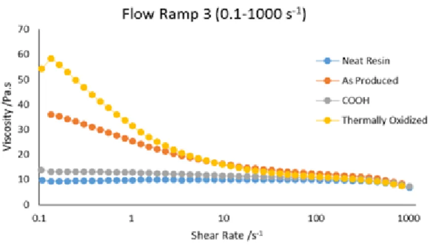
After the preparation of the samples rheological tests were performed, with the same equipment at 25 ºC. Figure 5.1 shows the relation between the shear rate and the viscosity of samples where thermally oxidized, CNTs functionalized with COOH groups and non-functionalized CNTs were used.
Figure 5.1 Relation between viscosity and shear rate of the dispersions with functionalized CNTs.
Analyzing Figure 5.1 is possible to conclude that the sample with lower viscosity is the one where the CNTs were functionalized with COOH groups. It is probable that the COOH groups attached to the CNT surface are not enough to increase their compatibility with the epoxy resin. CNTs functionalized with carboxylic acid groups are very often used to improve the adhesion between the CNTs and the matrix [47]. The thermally oxidized CNTs have increased the viscosity of the dispersion, this means that the use of thermally oxidized nanotubes leads to an increasing in the compatibility with the epoxy resin. The high viscosity is an indicative of stronger interfacial interactions [48]. The high viscosity at low shear rates can be attributed to the formation of a network by the CNTs [49]. This structure is then broken down when the shear rate increases, leading to similar viscosity of different dispersions at higher shear rates [48].
In Figure 5.1 is possible to observe that when thermally oxidized carbon nanotubes are used the viscosity is higher which indicates strong interfacial interactions, which in turn is related to a better network between the CNTs. In this case the better dispersion is achieved when thermally oxidized carbon nanotubes are used.
5.1.3 Effect of the Weight Fraction of CNTs
The concentration of CNTs in the dispersion is a parameter that needs to be controlled, because a large concentration of CNTs may lead to significant processing difficulties for carbon nanotube reinforced epoxy composites, such as poor wettability, heavy aggregation and high viscosity [17], [50], [51]. The high viscosity makes it difficult to disperse the nanotubes uniformly in the epoxy resins [13]. To evaluate the effect of CNT loading in the resin viscosity samples of different concentrations were prepared with pre-heating at 80ºC during 8 hours and then mixed using the mechanical stirrer at 2000 RPM during 60 minutes. Different concentrations of Arkema Graphistrenght carbon nanotubes were tested: 0.1 wt %, 0.3 wt %, 0.5 wt %, 0.7 wt % and 1 wt %. Some samples of non-functionalized CNTs (as produced) from FutureCarbon were also tested. In this case the concentrations used were 0.25 wt %, 0.5 wt %, 0.75 wt % and 1wt %. FutureCarbon CNTs come in a masterbatch with a weight fraction of 2 wt % and they are already dispersed and stabilized in the epoxy resin.
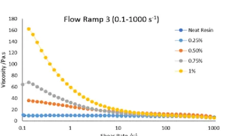
Rheological tests were carried out at 25 ºC. The results for the Arkema Graphistrenght carbon nanotubes suggests that with the increasing of the concentration of Arkema CNTs the viscosity were not increasing (Annex 1), meaning they were not de-agglomerated and therefore not well dispersed in the epoxy resin. Figure 5.2 shows the relation between the shear rate and the viscosity of the samples where FutureCarbon CNTs were used.
Figure 5.2 Relation between viscosity and shear rate of non-functionalized CNTs (as produced) from FutureCarbon with different weight fractions.
Observing Figure 5.2 it concludes that the neat resin presents itself as Newtonian fluid because its viscosity is independent of the shear rate [48]. With the increase of the weight fraction of CNTs the dispersion viscosity also increases, exhibiting a suspension behavior instead of a Newtonian behavior [38], [48]. The weight fraction of the CNTs in the resin affects the rheological behavior. Higher weight fractions imply a shorter distance between the CNTs therefore the mobility is reduced and the suspension’s resistance increases [49]. As the weight fraction increases CNTs develop a network in the suspension [49]. At lower shear rates this viscosity is high. At higher shear rates the network between the CNTs starts to break resulting in a lower viscosity [48], [52].
5.1.4 Effect of the Dispersing Agent
To verify the effect of the use of a dispersing agent on the viscosity of the samples the same experiments were repeated at 25 ºC. The dispersing agents used were a block copolymer and a rosin derivative, typically used as a pigment binder for coating formulations, with a weight fraction of 0.5 wt %. Initially, the effect of adding the dispersants to the neat epoxy pre-polymer was evaluated (Figure 5.3).
From Figure 5.3 it is possible to conclude that the use of different dispersing agents in the epoxy decreases the viscosity when comparing to the neat resin, this indicates that the dispersing agents used modify the rheological behavior of the resin. To prove the latter hypothesis this experiment was repeated at 25 ºC and was possible to obtain the same results. The results of the second assay are in Annex 1.
Figure 5.3 Relation between viscosity and shear rate when different dispersing agents are used in the epoxy.
5.1.5 Effect of the Dispersing Agent and Carbon Nanotubes
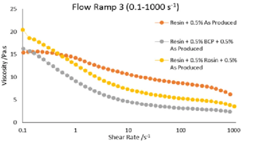
The effect of adding the dispersant to the CNT-loaded pre-polymer in its rheological behavior has been assessed. The CNTs used were the non-functionalized ones from FutureCarbon as well as from Arkema. Figure 5.4 depicts the relation between the viscosity and shear rate of the non-functionalized CNTs from FutureCarbon (As produced) and the dispersing agents. The rheological results of Arkema CNTs with and without dispersing agents were not analyzed, due to the difficulty in the dispersion of Arkema’s CNTs (Annex 1).
Figure 5.4 Relation between viscosity and shear rate of as produced CNTs and dispersing agents.
The CNTs increase the viscosity of the dispersion due to the formation of a network. By observation of the latter figure it is clear that there is a strong dependency between the viscosity and the shear rate, when the shear rate increases the viscosity decreases, this
agents modifies the rheological behavior of the resin loaded with CNTs, decreasing the viscosity when comparing only to the resin with CNTs. Therefore it is possible to obtain a good dispersion with the use of dispersing agents but with a lower viscosity.
5.1.6 Effect of the Functionalization in the Resin System
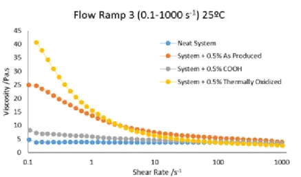
With the rheometer was also possible to test the system Araldite® LY 556, Aradur® 1571, Accelerator 1573 and HardenerXB 3471 with and without CNTs at 25 ºC. The CNTs used in the system were from FutureCarbon and were functionalized with COOH groups, thermally oxidized and non-functionalized (As Produced). Figure 5.5 shows the relation between viscosity and shear rate for the different types of CNTs used in the system.
Figure 5.5 Relation between viscosity and shear rate of the system with different types of carbon nanotubes.
Analyzing the last figure it concludes that the use of thermally oxidized CNTs increases the viscosity, this may indicate the formation of a network between the CNTs which increases the viscosity. Comparing the results of the resin system with the results of the resin with different types of CNTs the viscosity is higher in both cases for the thermally oxidized CNTs, followed by the non-functionalized CNTs (As Produced) and last for the CNTs functionalized with COOH groups.
The oxidation treatment of the CNTs remove amorphous carbon from their surface, this amorphous carbon could probably block sites, therefore reducing the reactivity of the CNT [53], [54]. The oxidation treatment also promotes the attachment of hydrophilic oxygenated functional groups and the attachment of oxygenated surface functional groups at defect sites on the CNTs, which can enhance the wettability of the CNTs in solutions [53]. Oxidation treatments directly attach carboxylic groups, and other oxygen bearing groups such as hydroxyl, carbonyl, ester and nitro groups to the ends or defects of the CNT [55]. The presence of these groups in the thermally oxidized CNTs may be the explanation to obtain a
higher viscosity when comparing to other CNTs. The presence of groups with oxygen can produce strong interfacial bonds with different polymers, including epoxies [13]. Carboxylic groups can undergo esterification reactions with the epoxy and the carbonyl groups present on the CNTs surface could bind to the epoxy resin through hydrogen bonds, and so these interactions could lead to a cross-linked network to the epoxy matrix [13], [51].
With the CNTs functionalized with COOH groups a higher viscosity is not observed. This could happen due to the fact of a low concentration of carboxyl groups on the CNT surface [48]. Although the non-functionalized CNTs do not contain functional groups they present a high viscosity than the CNTs functionalized with COOH groups. This might happen due to the formation of micro CNTs agglomerates in the resin; this network of micro-agglomerates connected with each other by separated CNTs might form a cross-linked network stronger than the one formed by the CNTs functionalized with COOH groups [49].
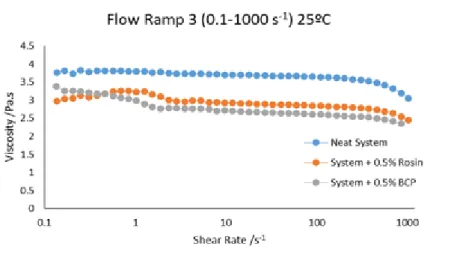
5.1.7 Effect of the Dispersing Agent in the Resin System
The dispersing agents used in the system were a rosin derivative and a block copolymer. The system was tested at 25ºC with and without dispersing agents. These results are shown in Figure 5.6.
Figure 5.6 Relation between viscosity and shear rate of the system with and without dispersing agents.
Analyzing the results it can be concluded that the use of dispersing agents in the system decreases the viscosity. In this case the use of 0.5 wt % of BCP decreases the viscosity of the system in 25%.
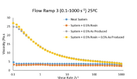
5.1.8 Effect of the Dispersing Agent and Carbon Nanotubes in the Resin System
Figure 5.7 Relation between viscosity and shear rate of the system with CNTs and rosin.
Figure 5.8 Relation between viscosity and shear rate of the system with CNTs and BCP. Analyzing both figures it is possible to conclude that the use of dispersing agents in the system decreases the viscosity of the system. However, the viscosity does not decrease when using CNTs and dispersing agents in the system comparing only with the viscosity of the system with the dispersing agents. This suggests that the use of dispersing agents might help to disperse the CNTs, through the creation of a network between the CNTs and therefore increasing the viscosity of the system. However, when introducing the dispersing agents in the system with the CNTs the effect of the dispersing agent in the viscosity is hampered.
5.2 Differential Scanning Calorimetry (DSC)
With the differential scanning calorimetry (DSC) technique it was possible to test the system Araldite® LY 1556, Aradur® 1571, Accelerator 1573 and HardenerXB 3471. Samples with different types of CNTs and with different dispersing agents were also in DSC with a heating rate of 10ºC/min. From the tests results was possible to obtain the heat flow as a
function of time to each heating rate. This allows the calculation of the heat of reaction, and the heat flow as a function of temperature, and eventually the glass transition temperature.
Table 5.1 summarizes the heat of reaction and glass transition temperature of two assays of the samples. These results refer only to the resin.
From inspection of the table it is obvious that the glass transition temperature is not significantly affected by the dispersing agent or the type of CNTs used. The heat of reaction for the B-stage and cure is also not significantly affected by the dispersing agent and type of CNTs. The differences seem to be in the range of the accuracy of the method.
Table 5.1 Heat of reaction and glass transition temperature of different samples with different dispersing agents and with different CNTs content.
Sample Glass Transition Temperature (ºC)
Heat of Reaction (J/g) B-stage Cure Assay 1 Assay 2 Assay 1 Assay 2 Assay 1 Assay 2 Neat System 111.39 113.57 65.39 70.63 304.9 305.0 System + 0.5 wt % Arkema CNTs 111.37 113.06 67.41 57.52 271.4 293.8 System + 0.5 wt % BCP 113.52 111.30 67.02 53.46 286.1 285.5 System + 0.5 wt % BCP + 0.5 wt % Arkema CNTs 109.68 112.63 67.40 68.75 277.9 286.1 System + 0.5 wt % Rosin 113.0 112.58 68.49 66.86 276.2 293.3 System + 1 wt % Rosin 112.69 110.60 69.68 71.86 296.5 280.1 System + 0.5 wt % Rosin + 0.5 wt % Arkema CNTs 110.61 113.98 76.82 57.43 300.1 291.3 System + 0.5 wt % As produced 112.36 114.13 66.01 56.34 274.7 281.0 System + 0.5 wt % BCP + 0.5 wt % As Produced 110.52 110.99 66.35 60.52 288.1 301.8 System + 0.5 wt % Rosin + 0.5 wt % As Produced 111.12 110.36 61.85 64.89 293.9 287.5 System + 0.5 wt % COOH 111.09 112.28 71.99 61.48 268.9 290.3 System + 0.5 wt % Thermally oxidized 109.19 112.75 67.68 55.17 289.6 315.5
Figure 5.9 shows the heat flow as a function of temperature for the neat system, system with 0.5 wt % of rosin derivative and system with 0.5 wt % of block copolymer – assay 1. In Figure 5.9 the results are related to the resin and dispersing agents.
Figure 5.9 Heat flow as a function of temperature for the neat system, system with 0.5 wt % of rosin and system with 0.5 wt % of BCP.
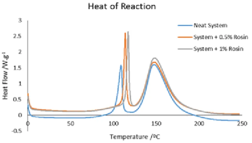
From Figure 5.9 it is possible to conclude that the introduction of rosin derivative in the system of the resin has a retardant effect in the b-stage, as the peak of the b-stage occurs at a higher temperature when comparing to the neat system. The use of BCP does not affect the cure reaction. To test the effect of rosin in the resin system a sample with 1 wt % of rosin was analyzed. Figure 5.10 shows the heat flow as a function of temperature of the neat resin system, system + 0.5 wt % of rosin and the system + 1 wt % of rosin.
Figure 5.10 Heat flow as a function of temperature of the neat resin system and the resin system with different weight fractions of rosin.
From the last figure it can easily be concluded that when a higher weight fraction of rosin derivative is used, a more intense retardant effect in the curing reaction is observed. This occurs because rosin derivatives are known to be possible inhibitors of the reaction. This inhibition occurs due to the protonation of the tertiary amines by the acid groups present in rosin derivative, this kind of reaction can produce a tertiary ammonium salt [56]. This reaction leads to the protonation of the nitrogen atom thus introducing a positive charge on it
and modifying the electronic environment. This reaction can be a reversible process with an equilibrium which can be displaced towards the starting materials [56].
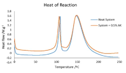
Figure 5.11 shows the heat flow as a function of temperature to neat system and for the system with 0.5 wt % of Arkema CNTs. In Figure 5.11 the results are related to the resin and carbon nanotubes.
Figure 5.11 Heat flow as a function of temperature for the neat system and the system with 0.5 wt % of Arkema CNTs.
From Figure 5.11 it is possible to conclude that the introduction of the Arkema CNTs has a catalytic effect during the cure. The CNTs increase the monomer conversion and cause the acceleration of the reaction rate, due to a catalytic effect [57], [58]. This catalytic effect can be caused by the existence of COOH groups in the CNTs or by the residual catalyst of untreated CNTs [57], [58]. Other possible reasons that had been found to contribute to the acceleration of the reaction are the higher thermal conductivity of the CNTs network and the physisorption of the hardener surrounding the CNTs [59].
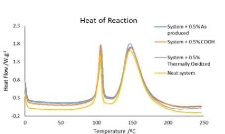
Figure 5.12 shows the heat flow as a function of temperature for CNTs with different types of functionalization. In Figure 5.12 the results are related to the resin and CNTs.
Figure 5.12 Heat flow as a function of temperature for different types of functionalization. From this figure is possible to see the effect of the functionalization of the CNTs in the resin system. The differences in the heat of reaction for the different types of CNTs are in the range of the experimental error. This means that the functionalization does affect the heat of reaction. Analyzing again the last figure it can be concluded that owing to the presence of different types of functionalization it is not possible to distinguish catalytic or anti-catalytic effects during the curing reaction.
Figure 5.13 shows the heat flow as a function of temperature of the neat system and the system with 0.5 wt % of rosin derivative and with 0.5 wt % of Arkema CNTs. In Figure 5.13 the results are related to the resin, dispersing agent and CNTs.
Figure 5.13 Heat flow as a function of temperature for the neat system, system with 0.5 wt % of rosin and system with 0.5 wt % of rosin and 0.5 wt % of Arkema CNTs.
Observing Figure 5.13 it is possible to conclude that the resin system with rosin and Arkema CNTs varies significantly. Although the use of rosin has a retardant effect in the
curing reaction, the introduction of 0.5 wt % of Arkema CNTs provides a tendency to accelerate the B-stage reaction.
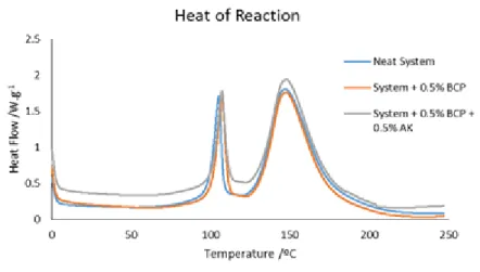
Figure 5.14 shows the heat flow as a function of temperature of the neat system, system with 0.5 wt % of BCP and system with 0.5 wt % of BCP and 0.5 wt % of Arkema CNTs. In Figure 5.14 the results are presented for the resin, dispersing agent and CNTs.
Figure 5.14 Heat flow as a function of temperature for the neat system, system with 0.5 wt % of BCP and system with 0.5 wt % of BCP and 0.5 wt % of Arkema CNTs.
From the last figure it concludes that the introduction of BCP does not produce any effect in the curing reaction. When the BCP is introduced in the system with the CNTs it is concluded that the latter have a catalytic effect in the curing reaction, due to the presence of residual groups or residual catalyst of the untreated CNTs [57], [58].
The results of the heat flow as function of the temperature for the system with As Produced CNTs are in Annex 2. In Annex 2 it is also possible to check the effect of the BCP, rosin derivative and CNTs. These results are consistent with the ones obtained with Arkema CNTs.
The graphs showing the method to obtain the heat of reaction and the glass transition temperature of the samples in the software TA Universal Analysis are in Annex 2.
5.3 Transmission Electron Microscopy (TEM)
The resin systems with different dispersing agents and with different types of CNTs were analyzed by TEM. In the pictures obtained by TEM it is possible to distinguish the agglomerates of CNTs at different magnifications. Figure 5.15 shows the TEM results for the resin system with 0.5 wt % Arkema CNTs, 0.5 wt % rosin and 0.5 wt % BCP with a
a) Resin system + 0.5 wt % Arkema CNTs b) Resin system + 0.5 wt % Arkema CNTs + 0.5 wt % BCP
c) Resin system + 0.5 wt % Arkema CNTs + 0.5 wt % rosin
Figure 5.15 TEM results for the resin system with Arkema CNTs and dispersing agents. From the last figure it is possible to see different agglomerates of CNTs with different sizes, and it is also possible to observe that the use of BCP decreases the number of agglomerates of CNTs with respect to the resin system + 0.5 wt % Arkema CNTs (b). Comparing this agglomerate with Figure 5.15 b), it is possible to conclude that with the use of the BCP there are less agglomerates but their size is larger than the ones found for the system without the BCP, the BCP may force the re-organization of the agglomerates – self-assembly [23]. Comparing Figure 5.15 c) with Figure 5.15 a) and b) it concludes that when rosin derivative is used as dispersing agent only a small effect is detected by TEM.
Figure 5.16 shows the TEM results for the resin system with 0.5 wt % as produced CNTs and with dispersing agents with a magnification of 12 000X.
a) Resin system + 0.5 wt % as produced CNTs b) Resin system + 0.5 wt % as produced CNTs + 0.5 wt % BCP
c) Resin system + 0.5 wt % as produced CNTs + 0.5 wt % rosin
Figure 5.16 TEM results for the system resin + 0.5 wt % as produced CNTs.
From Figure 5.16 is possible to see the effect of using dispersing agents. Comparing Figure 5.16 a) with Figure 5.16 b) and c) is possible to observe a less number of agglomerates. The agglomerates in the presence of the dispersing agents are also smaller than the ones formed without dispersing agents.
Figure 5.17 and Figure 5.18 shows the TEM results for the resin system + 0.5 wt % CNTs functionalized with COOH groups and the resin system + 0.5 wt % thermally oxidized CNTs, respectively.