Universidade de Aveiro Departamento deEletrónica, Telecomunicações e Informática 2012
André Filipe
Ferreira Prata
Gestão de ligações baseada em IEEE 802.21
Connection management based on IEEE 802.21
Universidade de Aveiro Departamento deEletrónica, Telecomunicações e Informática 2012
André Filipe
Ferreira Prata
Gestão de ligações baseada em IEEE 802.21
Connection management based on IEEE 802.21
Dissertação apresentada à Universidade de Aveiro para cumprimento dos requisitos necessários à obtenção do grau de Mestre em Engenharia de Computadores e Telemática, realizada sob a orientação científica do Doutor Diogo Nuno Pereira Gomes, Professor auxiliar convidado do Departamento de Eletrónica, Telecomunicações e Informática da Universidade de Aveiro, e do Doutor Pedro Alexandre de Sousa Gonçalves, Professor adjunto da Escola Superior de Tecnologia e Gestão de Águeda da Universidade de Aveiro.
o júri / the jury
presidente / president Professor Doutor António Luís Jesus Teixeira
Professor associado da Universidade de Aveiro
vogais / examiners committee Doutor Pedro Miguel Naia Neves
Investigador da Portugal Telecom Inovação
Professor Doutor Diogo Nuno Pereira Gomes
Professor auxiliar convidado da Universidade de Aveiro
Professor Doutor Pedro Alexandre de Sousa Gonçalves
agradecimentos /
Palavras Chave linux, 802.21, gestão de ligações
Resumo Avanços recentes nas telecomunicações conduziram a uma combinação de
várias interfaces de acesso à rede num único dispositivo. Os programas de gestão de ligações atuais lidam com as diferentes tecnologias indivi-dualmente, e baseiam a seleção da rede de acesso em parâmetros tais como a potência de sinal, ou taxa de transmissão máxima. Nem sempre estes mecanismos refletem a performance real de uma rede, levando a uma experiência de acesso fraca.
Neste trabalho é implementada uma framework de gestão de ligações inovadora, baseada na norma IEEE 802.21. Esta norma disponibiliza mecanismos que facilitam e otimizam handovers entre diferentes tecnologias e a seleção de ligações através da troca de informações entre as entidades da rede e o terminal, incluindo informação de QoS, desempenho ou outras características. Além disso, a norma permite a gestão de dispositivos independentemente da tecnologia, através de uma interface uniformizada ao nível da camada de ligação de dados.
Em virtude da extensão desta interface com mecanismos multi-camada, a nova framework possibilita a configuração asbtrata das interfaces de rede, incluindo a associação, configurações de segurança e endereçamento IP. O acesso a informação da rede capacita ainda os gestores de ligações para a realização de melhores decisões, tendo em conta o estado da rede e os requisitos das aplicações do terminal.
Esta framework é integrada com as ferramentas e applets de configu-ração de rede do sistema operativo GNU/Linux, através da substituição transparente da aplicação NetworkManager. Em comparação, a nova framework apresenta overhead insignificante, uma quantidade de código inferior e melhor consumo de bateria, além de mecanismos otimizados para ligação oportunística.
Keywords linux, 802.21, connection management
Abstract Recent advances in telecommunications have lead to the combination of various network access interfaces in a single device. Current network management software handles different technologies individually, and base connection decisions on parameters such as signal strength, or maximum throughput. Often, these network attributes do not reflect the real network perfomance, leading to poor network experience.
In this work, a novel network management framework is implemented, based on the IEEE 802.21 standard. This standard provides mechanisms to facilitate and optimize inter-technology handovers and network selection through information exchanges between network and terminal entities, including QoS and other network capability and performance information. Moreover, it enables media independent device management via a common link layer interface.
By extending this interface with cross-layer mechanisms, the new framework allows abstract configuration of the network interfaces, including network association, security setup procedures and IP address configuration. The access to network information will additionally empower network managers to perform better decisions that take network state and terminal application requirements into account.
This framework is integrated with the existing configuration tools and applets from the GNU/Linux Operating System, by seamlessly replacing the existing NetworkManager application. In doing so, the new framework shows insignificant overhead, a reduced code base and better battery consumption, on top of optimized procedures for opportunistic network attachment.
Contents
Contents i
List of Figures v
List of Tables vii
1 Introduction 1
1.1 Motivation and Goals . . . 1
1.2 Document outline . . . 3
2 Accessing the Internet 5 2.1 Network Device Technologies . . . 6
2.1.1 IEEE 802.3 . . . 7 2.1.2 IEEE 802.11 . . . 7 2.1.3 IEEE 802.16 . . . 8 2.1.4 Mobile Broadband . . . 9 2.2 Security Mechanisms . . . 9 2.3 Internet Protocol . . . 11
3 GNU/Linux Network Management 13 3.1 Kernel/Hardware interfacing . . . 14 3.1.1 ioctl . . . 14 3.1.2 sysfs . . . 15 3.1.3 Netlink sockets . . . 16 3.1.3.1 Route Netlink . . . 18 3.1.3.2 nl80211 . . . 23 3.2 Application interfacing . . . 27 3.2.1 Networking Sockets . . . 29 3.2.2 CORBA . . . 29 3.2.3 D-Bus . . . 29 3.2.3.1 Connection . . . 30 3.2.3.2 Interface . . . 30 3.2.3.3 Type system . . . 31 i
3.2.3.4 Summary . . . 31
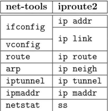
3.3 Individual network management tools . . . 32
3.3.1 Core tools . . . 32
3.3.2 Wireless tools . . . 33
3.3.3 Authentication supplicants . . . 34
3.3.4 DNS . . . 36
3.3.5 Dynamic Host Configuration Protocol (DHCP) clients . . . 36
3.4 Full-featured network management Solutions . . . 37
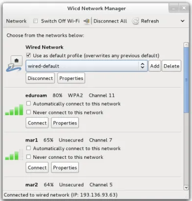
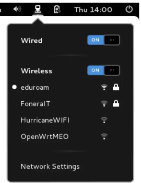
3.4.1 wicd . . . 37 3.4.2 NetworkManager . . . 38 3.4.2.1 org.freedesktop.NetworkManager . . . 39 3.4.2.2 org.freedesktop.NetworkManager.Device . . . 40 3.4.2.3 org.freedesktop.NetworkManager.Device.Wired . . . 41 3.4.2.4 org.freedesktop.NetworkManager.Device.Wireless . . . 41 3.4.2.5 org.freedesktop.NetworkManager.AccessPoint . . . 41 3.4.2.6 org.freedesktop.NetworkManager.Settings . . . 42 3.4.2.7 org.freedesktop.NetworkManager.Settings.Connection . . . . 42 3.4.3 Acceptance . . . 43 3.5 Conclusion . . . 43
4 Institute of Electrical and Electronics Engineers (IEEE) 802.21 45 4.1 Motivation . . . 45
4.2 Architecture . . . 46
4.2.1 Media Independent Event Service . . . 48
4.2.2 Media Independent Command Service . . . 48
4.2.3 Media Independent Information Service . . . 50
4.2.4 Media Specific Mappings for Service Access Points (SAPs) . . . 50
4.3 Open Dot Twenty ONE . . . 50
4.4 Extending 802.21 towards Media Independent Network Management . . . 51
4.4.1 IEEE 802.21 extensions . . . 52
4.5 Conclusion . . . 55
5 EMICOM Implementation 57 5.1 D-Bus integration . . . 58
5.2 Route Netlink and nl80211 wrappers . . . 59
5.3 Management Processes . . . 60
5.3.1 Startup . . . 60
5.3.2 Connect . . . 61
5.3.3 Disconnect . . . 62
5.4 Link SAPs implementation . . . 62
5.4.1 Initial Setup . . . 62
CONTENTS iii
5.4.3 Link Up event . . . 64
5.4.4 Link Down event . . . 65
5.4.5 Link Parameters Report event . . . 65
5.4.6 Link Going Down event . . . 66
5.4.7 Link Handover Imminent event . . . 67
5.4.8 Link Handover Complete event . . . 67
5.4.9 Link PDU Transmit Status event . . . 67
5.4.10 Link Conf Required event . . . 67
5.4.11 Link Capability Discover command . . . 68
5.4.12 Link Event Subscribe command . . . 68
5.4.13 Link Event Unsubscribe command . . . 69
5.4.14 Link Get Parameters command . . . 69
5.4.15 Link Configure Thresholds command . . . 69
5.4.16 Link Actions command . . . 71
5.4.17 Link Conf command . . . 71
5.4.18 L3 Conf command . . . 72
5.5 Media Independent Handover Function (MIHF) Extension . . . 73
5.6 Network Manager implementation . . . 73
5.6.1 Network Manager . . . 74 5.6.2 Settings . . . 74 5.6.3 Device . . . 75 5.6.4 DeviceWired (Ethernet) . . . 75 5.6.5 DeviceWireless (Wi-Fi) . . . 76 5.6.5.1 AccessPoint . . . 76 5.7 Summary . . . 77 6 Evaluation 79 6.1 Test Setup . . . 79
6.2 Inter process overhead . . . 80
6.3 Code base . . . 82
6.4 Memory usage . . . 82
6.5 Benefits . . . 83
6.5.1 Battery life . . . 83
6.5.2 Optimal selection . . . 84
7 Conclusions and Future Work 87 7.1 Contributions . . . 87
7.2 Future work . . . 88
Bibliography 91
List of Figures
3.1 Intel protection rings. . . 13
3.2 Linux device model. . . 15
3.3 Netlink message format. . . 17
3.4 Generic Netlink Message format. . . 18
3.5 Linux Wireless layered interface. . . 23
3.6 wicd ’s graphical user interface window. . . 38
3.7 NetworkManager ’s configuration Graphical User Interface (GUI). . . 39
3.8 Gnome’s NetworkManager applet. . . 40
4.1 IEEE 802.21 Reference Model . . . 47
4.2 IEEE 802.21 General Architecture. . . 47
4.3 General MIHF reference. . . 51
4.4 IEEE 802.21 architecture for network management. . . 52
4.5 Architectures for 802.21 based Network Manager. . . 53
5.1 EMICOM architecture. . . 58
5.2 Message signalling for framework startup. . . 60
5.3 Message signalling for a connection request. . . 61
5.4 Message signalling for a disconnection request. . . 62
5.5 Link SAP implementation diagram. . . 63
5.6 Threshold configuration command handling. . . 70
5.7 Network Manager Media Independent Handover (MIH) User components. . . 74
5.8 Example of carrier detection feedback. . . 76
6.1 Testbed architecture. . . 80
6.2 Battery drain comparison. . . 84
6.3 Optimal AP selection for throughput. . . 85
List of Tables
3.1 net-tools replacement by iproute2. . . 33
3.2 Comparison between wireless-tools and iw tools. . . 33
6.1 Computer attributes. . . 79
6.2 MIH message sizes. . . 80
6.3 Network configuration timings, in seconds. . . 81
6.4 Code base comparison, in number of source code lines. . . 82
6.5 Memory allocated by each solution, in bytes. . . 83
List of Acronyms
3GPP 3rd Generation Partnership Project
AAA Authentication, Authorization and Accounting ABC Always Best Connected
AES Advanced Encryption Standard AP Access Point
API Application Programming Interface ARP Address Resolution Protocol
ASCII American Standard Code for Information Interchange BS Base Station
BSS Basic Service Set
CCMP Counter Cipher Mode with Block Chaining Message Authentication Code Protocol
CID Connection Identifier
CORBA Common Object Request Broker Architecture CoS Class of Service
CPU Central Processing Unit CQM Connection Quality Monitor CRDA Central Regulatory Domain Agent DCOP Desktop Communication Protocol DE Desktop Environment
DHCP Dynamic Host Configuration Protocol DHCPv4 DHCP version 4
DHCPv6 DHCP version 6 DNS Domain Name System DSL Digital Subscriber Line
EAP Extensible Authentication Protocol EAPoL EAP over LAN
EEPROM Electrically Erasable Programmable Read-Only Memory ESS Extended Service Set
ETSI European Telecommunications Standards Institute FTP File Transfer Protocol
GCC GNU Compiler Collection GPRS General Packet Radio Service
GSM Global System for Mobile communication GTK+ GIMP Toolkit
GUI Graphical User Interface HESSID Homogeneous ESS Identifier IBSS Independent Basic Service Set ICMP Internet Control Message Protocol
IEEE Institute of Electrical and Electronics Engineers IE Information Element
IPC Inter-Process Communication IP Internet Protocol
IPsec Internet Protocol Security IPv4 IP version 4
IPv6 IP version 6
ISC Internet Systems Consortium KDE K Desktop Environment LAN Local Area Network
List of Tables xi
LEAP Lightweight Extensible Authentication Protocol LLC Logical Link Control
LSAP Link Service Access Point LTE Long Term Evolution
LXDE Lightweight X11 Desktop Environment MAC Media Access Control
MIB Management Information Base
MICS Media Independent Command Service MIHF Media Independent Handover Function MIH Media Independent Handover
MIIS Media Independent Information Service
MN Mobile Node
MTU Maximum Transmission Unit NAT Network Address Translation NTP Network Time Protocol OS Operating System PDU Protocol Data Unit
PID Process ID
PIN Personal Identification Number PKI Public Key Infrastructure PMK Pairwise Master Key
PMKSA Pairwise Master Key Security Association PoA Point of Attachment
PoS Point of Service
PUK Personal Unblocking Code QoS Quality of Service
RAII Resource Acquisition Is Initialization RC4 Rivest Cipher 4
RSSI Received Signal Strength Indicator SAP Service Access Point
SIM Subscriber Identity Module SNR Signal to Noise Ratio
SINR Signal over Interference plus Noise Ratio SMS Short Message Service
SNMP Simple Network Management Protocol SSID Service Set Identifier
SS Subscriber Station
TCP Transmission Control Protocol TKIP Temporal Key Integrity Protocol TLV Type-Length-Value
TOS Type of Service
UDP User Datagram Protocol
UMTS Universal Mobile Telecommunications System URL Uniform Resource Locator
USB Universal Serial Bus
VLAN Virtual Local Area Network VPN Virtual Private Network WEP Wired Equivalent Privacy WEs Wireless Extensions
WIMAX Worldwide Interoperability for Microwave Access WLAN Wireless Local Area Network
WMAN Wireless Metropolitan Area Network WPA2 Wi-Fi Protected Access 2
List of Tables xiii
WPA Wi-Fi Protected Access WPS Wi-Fi Protected Setup XML Extensible Markup Language
Chapter 1
Introduction
The Internet has steadily gained popularity from its first days to the point that, in 2011, one third of the world population was estimated to be using it [1]. This fact is attributed to the widespread use of computers and, more recently, mobile phones. These devices enable virtually instant access to information, entertainment as well as voice and video communications across the globe.
Various physical and logical data communication technologies emerged for interconnecting these devices. Nowadays, most computers and smartphones offer at least two network access interfaces. Computers can also be coupled with after-market dongles for access to additional network technologies. Some technologies are focused on high throughput for stationary de-vices, while others attempt to provide mobile access in geographically broad areas. Various technologies combined in a single device complement each other, enabling the device to adapt to the network scenarios that better support its purpose.
1.1
Motivation and Goals
The combination of multiple network technologies in a single device requires a management entity for controlling each device and chose, at any given time, the best interface for network access. To achieve this, modern Operating Systems (OSs) usually have a component called a Network Manager. Network Managers offer a high level interface to control the physical and logical properties of the network interfaces, and usually provide Graphical User Interfaces (GUIs) for users to configure network parameters and connectivity preferences.
Currently, there is a myriad of connection management software for mobile terminals. They are usually distributed as pre-installed software by Operating Systems or device ven-dors, and also integrated with device driver bundles, provided by network interface vendors and operators. When provided by Operating Systems, these programs are meant as generic solutions that attempt best at keeping an active connection with every available interface (although it is usually possible to configure mutual exclusion). Operators, on the other hand, develop custom software in order to introduce added value associated with their provided services. Depending on the operator, this includes the ability to track data usage, place calls
or Short Message Service (SMS) interactions, locate operator hotspots, etc. The following set of issues can be detected in virtually every connection management solution:
• OS portability: there is a multitude of available Operating Systems that provide different programmable interfaces and technologies for network management. While there are software technologies that allow high level programs to run in different OSs, network management software must deal with low level aspects of the machine for which there are no OS-independent frameworks.
• Technology independence: network manager implementations are tied to specific hardware technologies as much as they are to the OS on which they are deployed. Different technologies require different control primitives, which in turn result in the need for different software drivers and programmable interfaces. As such, Network Managers are usually tailored for a few specific network technologies, leaving the others out of the supported feature list.
• Network communication: existing Network Managers usually take into account var-ious metrics about each network in order to select the best possible connection, such as “signal quality”, or maximum “bit rate”. More often than not, these metrics result in bad network selection decisions, since the experience provided by a network greatly depends on a number of factors that clients cannot perceive, such as the load of a network end-point. However, the network knows about these factors, and may issue information that helps clients better choose points of attachment. Some operators implement proprietary solutions to address this problem.
• Application requirements: there is no single “best network” for any given scenario. Depending on the applications and services a terminal is running, the perceived user experience may depend on available throughput, minimum latency, or other network policies. These variables seldom determine network selection, as this information is not available prior to attachment to a target network.
With different kinds of access technologies available to multi-interface mobile terminals, achieving an optimal network selection decision depends on multiple parameters [2], ranging from:
1. The dynamics of the wireless strata (e.g., Signal to Noise Ratio (SNR), available band-width, cell load);
2. Requirements placed by the service content being accessed (e.g., minimum latency); 3. Requirements placed by the user (e.g., perceived video and/or audio quality, cost); 4. Network conditions (e.g., cell load, requested service, policies).
The different criteria involved must not only take into consideration the capabilities of the service being provided, but also the resources available in the network and, ultimately,
1.2. DOCUMENT OUTLINE 3
the user satisfaction. As such, optimal decisions have the need to assess different objectives, from different layers of the network stack, in order to achieve an Always Best Connected (ABC) [3] solution. In this sense, different schema are possible, varying between mobile terminal centric decisions [4], network controlled decisions [5], or even combinations of both where the perspective of the terminal and network come together to optimize the handover decision to a broader set of requirements [6].
A new IEEE standard, by the 802.21 [7] group, defines a technology independent interface for handover optimization. This interface targets link layer operations, and standardizes communication between network and terminal entities in order to facilitate decisions regarding network handovers. The goal of this dissertation is to leverage from this standard, extending it when necessary, in order to provide an Enhanced Media Independent COnnection Manager (EMICOM) framework that will enable enhanced network management with the previously enumerated issues in mind. The framework is to be integrated with the GNU/Linux desktop OS by seamlessly replacing the most widely used Network Manager for the platform.
1.2
Document outline
The remainder of the document is structured as follows. Chapter 2 introduces some of the most common network technologies and requirements for Internet access. Chapter 3 exposes the GNU/Linux platform from the point of view of a programmer targeting the control of network devices and protocols, as well as the integration with other desktop applications. This is followed by an overview of the existing network management tools for the platform. Chapter 4 presents the new IEEE 802.21 standard and an open-source implementation of the protocol. Some required extensions to the protocol are proposed in the same Chapter, in order to allow network management tasks. The developed framework is described in Chapter 5, and evaluated in Chapter 6. Finally, Chapter 7 concludes and gives an insight of future work based on this dissertation.
Chapter 2
Accessing the Internet
In telecommunications, passing information from one point to another comprises a complex series of interactions. Any group of devices passing information between one another is said to form a network. Two networks can be interconnected to form a larger network; this is the origin of the term Internet (short for Internetwork); it is a large network of networks that is supported by a considerably large amount of devices (hardware) and programs (software). The Internet architecture is based on a layered stack that isolates protocols in different layers [8]; new protocols can be introduced in one layer without affecting other layers or protocols. When data is sent from one device to another on a network, it travels down these layers in the form of packets, which are then physically transported to the destination, where they will travel up the stack until they arrive at the intended program. At the top of the protocol stack is the client of the Internet itself, the software that is looking to transmit data to another host; the bottom concerns to the device that effectively transmits the data through the physical medium. In between are the following four layers considered by the Internet architecture [8]: • Application (or Layer 5): software clients of the Internet design their own protocols for distributed communication, such as the File Transfer Protocol (FTP), for transferring files over the Internet.
• Transport (or Layer 4): several applications can use the Internet concurrently from the same system. The protocols in the transport layer assign each application a number, called port, that allows unequivocal delivery of packets to the intended client. Such is the case of the Transmission Control Protocol (TCP), whose goal is also to implement a reliable, ordered delivery of packets between clients.
• Internet (or Network Layer, or Layer 3): the Internet Protocol (IP) itself is defined in this layer. It solves the problem of correctly forwarding the packets, if necessary through intermediate routers, to the desired recipient. As the name points out, it is the core of the Internet, and will be further detailed in section 2.3.
• Link (or Layer 2): this layer provides means to address devices physically, through Media Access Control (MAC) addresses, as well as controlling the access to the shared,
physical medium, including collision detection. MAC addresses are uniquely attributed by device vendors, but some devices allow to manually assign different addresses. This layer usually imposes a limit on frame size for transmission, labeled the Maximum Transmission Unit (MTU); the Network layer handles fragmentation for packets larger than this limit.
Many devices support Internet access, the most generally known to the user being the computers, smartphones and tablets. Acquiring network connectivity encompasses the con-figuration of certain aspects of the Internet Protocol. Some networks also employ security mechanisms that hosts must support. However, the first step towards network connectivity is the physical setup of the devices, which varies with technology.
2.1
Network Device Technologies
Network devices are mainly grouped in two categories: wired and wireless. Wired devices usually communicate with each other through a cabled medium, the most common being based on copper. Fiber optics is replacing the copper for the newer, higher performing networks, based on guided beams of light instead of electric current. Wireless devices rely on antennas that irradiate electromagnetic waves to broadcast information over the air.
The first requirement for network connectivity in wired technologies is simple: correctly setup the cables between the devices. Different standards define the requirements that the network cables must conform to, such as maximum length and impedance; as long as the cables conform to these requirements, attaching a cable will enable physical connectivity on a network.
Attaching wireless nodes introduces further complexity, because electromagnetic signals have a limited range that depends on the power of the transmitting device, the sensibility of the receiving interface, and the physical elements or obstacles in between. Electromagnetic signal strength decreases with range, and there is no way to evaluate the availability of signal range in the same way a cable attachment is determined. However, it is possible to measure the strength of a signal, as perceived by the receiving device. The usual metric for the “present signal” is the Watt. Since the strength of an electromagnetic signal is inversely proportional to the square of the distance from the source, the strength is best represented in a logarithmic scale of the measured Watt value. This is called dBmW (or just dBm), for decibel of the measured power referenced to one milliWatt (mW ), represented by the formula dBm = 10 log(mW ). The amount of signal energy that determines whether communication is possible varies with specific devices and network technologies.
Networks are also grouped in respect to their geographical span. It is common to consider Personal, Local, Metropolitan and Wide Area Networks. Wireless Metropolitan and Wide Area Networks, including IEEE1 802.16 and Cellular technologies such as 3rd Generation Partnership Project (3GPP)2standards, offer greater mobility due to their wider geographical
1
Institute of Electrical and Electronics Engineers, http://www.ieee.org/
2
2.1. NETWORK DEVICE TECHNOLOGIES 7
coverage. Local Area Networks (LANs) usually deliver higher bandwidths, and are very common at home and office environments, the most relevant being the IEEE 802.3 and 802.11 technologies.
2.1.1 IEEE 802.3
IEEE 802.3 [9] is the working group defining the physical and link layer’s MAC of the wired network technology known as Ethernet. Many Ethernet standards were introduced over the years, improving on the network capacity past the gigabit per second throughputs. The first versions relied on coaxial cable buses, later replaced with twisted pairs and optical fiber cabling.
The technology may be used to create a direct connection between two devices, but the infrastructure targets more complex setups of many hosts interconnected by devices such as Hubs and Switches. Hubs are used to connect multiple network interfaces together, making them act as a single network segment. Switches commute packets between segments, depend-ing on link layer packet destination address, thus preventdepend-ing unnecessary bus occupation on the other segments.
2.1.2 IEEE 802.11
IEEE 802.11 [10] is the set of standards for implementing Wireless Local Area Network (WLAN) computer communication, from which the commercial Wi-Fi technology originates. Instead of cables, these networks operate over the electromagnetic spectrum, namely in the 2.4, 3.6 and 5GHz frequency bands, each divided in several channels.
A group of Stations communicating with one another over 802.11 forms a Basic Service Set (BSS). When all of the stations in the BSS are mobile stations and there is no connection to a wired network, the BSS is called Independent Basic Service Set (IBSS). An IBSS is a typically short-lived network, with a small number of stations, that is created for a particular purpose. In this mode (IBSS) there is no single master, and every station can directly communicate with each other. When a BSS includes an Access Point (AP), it is called Infrastructure BSS. When there is an AP, if one mobile station in the BSS must communicate with another mobile station, the communication is sent first to the AP and it is retransmitted from the AP to the destination mobile station.
Multiple interconnected BSSs form an Extended Service Set (ESS), where the APs com-municate among themselves to forward traffic from one BSS to another, and to facilitate the movement of mobile stations between BSSs. ESSs are identified by a Service Set Identi-fier (SSID), which is a chosen string of octets with the maximum size of 32 bytes. Wi-Fi is connectionless and contention-based, meaning that there is no guaranteed logical link between a station and an AP, and that stations dispute the right to send packets every time they wish to.
Stations register with the AP in order to establish layer 2 connectivity. This process com-prises two phases: authentication and association. If a station desires to attach to a different
AP in the same ESS, it roams by performing a reassociation to the new AP. Associating and Disassociating is the Ethernet equivalent of attaching and detaching a cable.
Stations know APs exist because they send periodic beacons. Sensing the electromagnetic spectrum for these beacons is called passive scanning. Active scans are performed by actively broadcasting probe request frames on the desired channels.
The 802.11 standard defines an arbitrary unit for signal measurement, called Received Signal Strength Indicator (RSSI). Vendors are free to define an RSSI_Maximum value, within the one byte range (up to 256 different levels), and there is no standard mapping between a dBm value and the resulting RSSI metric. Regardless of the vendor, it is common to derive a percentage metric of the signal strength by dividing current RSSI values by the arbitrary RSSI_Maximum (and then multiplying by 100). Although percentages do not translate to any dBm or mW value, a vendor would acknowledge that a perceived signal equal to RSSI_Maximum (100%) would be great, and assign to 0% the inability to sense any energy at all.
2.1.3 IEEE 802.16
The IEEE 802.16 group defines the standards for Wireless Metropolitan Area Networks (WMANs), resulting in a technology commercialized under the name Worldwide Interop-erability for Microwave Access (WIMAX). The standard was developed to deliver connectiv-ity between Subscriber Stations (SSs) and Base Stations (BSs) with typical non-line-of-sight cell radius of three to ten kilometers in the 2 to 11GHz frequency bands, and line-of-sight distribution service in the 10 to 66GHz bands [11].
IEEE 802.16 is connection-oriented; all services, including inherently connectionless ser-vices, are mapped to a connection. This provides a mechanism for requesting bandwidth, associating Quality of Service (QoS) and traffic parameters, and other actions associated with contractual terms of the service. Connections are referenced with Connection Identi-fiers (CIDs), and may require continuously granted or on-demand bandwidth. Upon associa-tion with a BS, an SS is assigned three management connecassocia-tions in each direcassocia-tion:
• The basic connection, which is used for the transfer of short, time-critical physical and link layer control messages.
• The primary management connection, used to transfer longer, more delay-tolerant mes-sages such as those used for authentication and connection setup.
• The secondary management connection, used for the transfer of standards-based man-agement messages such as Dynamic Host Configuration Protocol (DHCP) and Simple Network Management Protocol (SNMP) messages.
In addition to these management connections, Subscriber Stations are allocated transport connections for the contracted services. Transport connections are unidirectional and assigned in pairs, to facilitate different uplink and downlink QoS and traffic parameters.
2.2. SECURITY MECHANISMS 9
2.1.4 Mobile Broadband
The 3GPP develops mobile Internet access technologies with capacity and throughput en-hancements, through radio interface changes and incremental improvements to existing mobile telephony core network (both packet and circuit-switched). Several technologies have been standardized by the group, including the General Packet Radio Service (GPRS), the Universal Mobile Telecommunications System (UMTS) and, more recently, Long Term Evolution (LTE). GPRS, originally standardized by the European Telecommunications Standards Institute (ETSI)1, is a 2.5G mobile communications technology that enables mobile wireless service providers to offer their mobile subscribers packet-based data services over Global System for Mobile communication (GSM) networks [12]. Common applications of GPRS include Internet access, intranet/corporate access, instant messaging, and multimedia messaging. It is a best-effort service, implying variable throughput and latency that depend on the number of other users sharing the service concurrently.
UMTS is a 3G mobile communications technology that offers higher throughput, real-time services, and end-to-end QoS [13]. It offers both connection-oriented and connectionless ser-vices for point-to-point and point-to-multipoint communication. UMTS network serser-vices have different QoS classes for various types of traffic: conversational (voice and video telephony), streaming (video on demand), interactive (web browsing, gaming) and background (e-mail, SMS).
LTE is the 3GPP proposal for simplifying the internal architecture of the system and reducing network costs and latencies by transiting from the previous packet and circuit-switched combined network to a pure packet-circuit-switched, all-IP network [14, 15]. LTE has introduced a number of new technologies when compared to the previous cellular systems, achieving what is called a “flatter architecture”; data is no longer routed by traversing a hierarchy from the originating user through multiple layers of aggregation to a central core, and then re-routed back out in a multilayer dis-aggregation hierarchy to the targeted user.
In terms of protocols and infrastructure, mobile broadband networks are still considerably more complex than the previous technologies. They are commonly accessible through cell-phones, smartphones and tablets. Computers usually depend on peripheral modems attached by Universal Serial Bus (USB).
2.2
Security Mechanisms
Many network technologies offer security mechanisms in order to limit network access to a specified group of people or devices, or to prevent data inside a network from being accessed from the outside. This issue is more common in wireless networks, since the data is inherently broadcasted over the air and not concealed in cables. One basic measure for preventing access from someone outside a network is to ignore all traffic from a specified link layer addresses.
1
This is efficient, but not very effective, because link layer addresses can be forged. It also does not imply any sort of protection of the data being transported.
Mobile broadband technologies usually require Subscriber Identity Module (SIM) cards on host devices for authentication purposes. A SIM card has both a memory and a small processing unit [16]. Part of the memory is accessible by the user, but another part, written by the operator, is protected and contains a secret key. SIM cards are only accessible after being provided a Personal Identification Numbers (PINs), and are blocked after a certain number of wrong PIN inputs. A Personal Unblocking Code (PUK) enables reactivating the SIM card, but failing this code a number of times will render the device irrevocable unusable. Other common security mechanisms rely on secret material that is provided to the network layer by supplicant software. The original IEEE 802.11 standard proposed a security algorithm that aimed at providing data confidentiality compared to that of a traditional wired network, named Wired Equivalent Privacy (WEP) [17]. The algorithm was very efficient and easy to implement in both hardware and software, making it ideal for link layer security. It was based on a stream cipher generated by the WEP Algorithm (based on Rivest Cipher 4 (RC4)), with the initial inputs being a fixed-length key (previously shared and secretly stored by both Stations and APs) and an Initialization Vector (changed as frequently as every packet). WEP was found to contain several weaknesses [18, 19, 20], which were incorporated into software that helps to gain access to a network in a matter of seconds1.
In its draft version, the IEEE 802.11i amendment proposed a new algorithm called Wi-Fi Protected Access (WPA) [21]. It was still based on the RC4 cipher and could be implemented through simple firmware upgrades to existing IEEE 802.11 devices. The main change to the WEP algorithm was that the inputs for the pseudorandom generator were less predictable; the Initialization Vector concept remained intact, but the shared key also changed for each packet, as described in the Temporal Key Integrity Protocol (TKIP). The final version of the standard implemented a new protocol, Wi-Fi Protected Access 2 (WPA2). No longer based on RC4, it replaced TKIP with the CCMP2 protocol, based on the Advanced Encryption Standard (AES) algorithm. In most cases, new hardware was required for the new algorithm; the 2007 IEEE 802.11 standard included these amendments, and support for the newer algorithm was mandatory for Wi-Fi certification. Wi-Fi Protected Setup (WPS) was later introduced by the Wi-Fi Alliance3, as an optional feature. It allows easier setup of a secure connection; instead of requiring long password inputs on every device, it allows negotiation of keys through the push of a button on the AP, or using a smaller PIN code.
All methods referred for IEEE 802.11 networks are based on a shared key that must be distributed through all the devices. This is most common in personal networks; corporate setups are usually combined with the IEEE 802.1X [22] standard. It defines the encapsulation of the Extensible Authentication Protocol (EAP) [23] over local and metropolitan networks. This protocol requires a dedicated Authentication, Authorization and Accounting (AAA)
1
aircrack suite, http://www.aircrack-ng.org/
2
Counter Cipher Mode with Block Chaining Message Authentication Code Protocol
3
2.3. Internet Protocol 11
server such as RADIUS or Diameter. EAP is just a framework that specifies the transport of keying material, and supports many authentication methods. There are methods based on simple identity/password pairs, while more complex methods provide mutual identification through the use of Public Key Infrastructure (PKI) tokens. Some methods are based on SIM cards and other hardware-based mechanisms.
2.3
Internet Protocol
The first major version of the Internet Protocol was IP version 4 (IPv4) [24]. IP version 6 (IPv6) [25] is the widely supported version for replacing IPv4, with the most prominent change being the addressing space, now using 128 bit instead of the previous 32. IP addresses can be manually or dynamically allocated to devices. Some classes of addresses are intended for global connectivity, and are uniquely assigned to a particular device; others are limited to communication inside local networks (subnets). Two different subnets may allocate the same range of addresses to their devices without collision. Devices without global addresses are able to reach devices outside that scope through Network Address Translation (NAT) [26]. The Internet Control Message Protocol (ICMP) [27, 28] is used by devices for diagnostic and control purposes at the network layer. For example, an ICMP Echo Request is a message used to test whether a device exists with a given IP address.
Other than manually assigning IP addresses, there are protocols for automatic, dynamic attribution, like the DHCP [29, 30]. This is an application layer protocol; despite dealing with network layer configuration, it works by broadcasting User Datagram Protocol (UDP) packets over the network using a null source IP address and special UDP port reserved for the protocol. DHCP servers listen to these messages and respond by allocating (leasing) an unused IP address to the host. Leases expire after a period of time; if the host is still in the network, it is expected to attempt and renew the lease before it expires. After a lease expires, or if it is explicitly released, the DHCP server considers the IP address free for leasing to another host.
The IPv6 protocol defines an additional method for devices to configure themselves inde-pendently. It is called stateless autoconfiguration [31], in contrast with the “stateful” DHCP version 6 (DHCPv6) method, which depends on information provided by a dedicated server, that keeps track of the addresses for each device. The stateless mechanism allows a host to generate its own addresses using a combination of locally available information and informa-tion advertised by routers. Routers advertise prefixes that identify the subnet(s) associated with a link, while hosts generate an "interface identifier" that uniquely identifies an interface on a subnet (usually based on the link layer address). An address is formed by combining the two. In the absence of routers, a host can only generate link-local addresses. However, link-local addresses suffice for communication among nodes attached to the same link.
Other than IP addresses, DHCP servers provide additional bootstrap configurations in-cluding, among many others: static network routes, Network Time Protocol (NTP) servers and Domain Name System (DNS) servers. The DNS [32, 33] protocol is used to translate
do-main names (e.g. www.ua.pt) into IP addresses. This allows humans to reach servers without knowing their IP addresses, which are much harder to remember.
Chapter 3
GNU/Linux Network Management
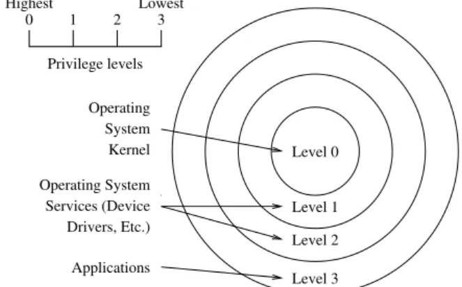
Modern Central Processing Units (CPUs) define several privilege levels for executed code. The Intel1 64 and IA-32 Architecture [34] processors, for example, support 4 levels, with level 0 being the most restrictive, and 3 the least privileged, as depicted in Figure 3.1. Typically, level 0 corresponds to OS kernel code. In Linux this includes the typical memory management and input/output, but also driver modules, since they are compiled directly or as modules to the kernel. This is the only level at which software directly controls hardware; code running without such privileges is said to run in userspace. Linux considers only these two levels.
Privilege levels 0 1 2 3 Lowest Highest Operating System Kernel Operating System Services (Device Drivers, Etc.) Level 0 Level 1 Level 2 Level 3 Applications
Figure 3.1: Intel protection rings.
Network Managing is a process that occurs at high level, including user interaction, but it implies hardware management as well. Also, many user applications might need to interact with the Network Manager itself in order to gather or control network information. The processes by which applications pass information between each other is called Inter-Process Communication (IPC).
To interact with the Operating System and hardware, programs need to have the kernel carry out operations for which they do not have the required privileges (manipulation of hardware and the kernel itself). Such mechanisms are usually referred to as system calls, or syscalls, for short.
1
Intel, http://www.intel.com/
Section 3.1 will start by discussing system calls and other derived kernel interfaces, followed by an overview of IPC frameworks in Section 3.2. Sections 3.3 and 3.4 will present the most common tools and full-featured solutions for Network Managing, respectively.
3.1
Kernel/Hardware interfacing
The Linux kernel provides a set of different syscalls for different, specific operations. Two complementary examples are the open() and close() syscalls. A call to open() provides the user with a file descriptor for a file that either exists or is to be created by the operation. This file descriptor is the information that the process holds and must use for subsequent operations on the file, including writing (write()), reading (read()) and closing (close()). Other than file management, the Linux kernel provides system calls for process and mem-ory control (execl(), exit(), . . . ), system maintenance (gettimeofday(), settimeofday(), . . . ) and communication (send(), recv(), . . . ), among other standard services. However, a limited set of syscalls will never suffice for interaction with all existing and newly created hardware devices. Each system call must be officially assigned a unique number, and and its behavior and interface must not change through time. To avoid this problem in providing new device interfaces, a special syscall was created for control of non-standard hardware – ioctl().
3.1.1 ioctl
ioctl is an abbreviation of input/output control, and provides an interface for operations on special files. Unlike common system calls, it can be called with a different number and type of parameters, depending on the intended destination and action to carry out. The call has the following signature:
# i n c l u d e < sys / i o c t l . h >
int i o c t l ( int d , int request , . . . ) ;
To enact a generic interface, the method takes as parameters: a file descriptor, a request code number, and an optional pointer to arbitrary data for extra parameters1. The file descriptor identifies the destination itself. The request code number is an identifier, specified by the device driver, to indicate the action that is to be executed. Depending on the action, the additional parameter may refer to input arguments, output values, or both; this parameter was traditionally identified as char *argp, but the ellipsis were introduced later, to prevent type checking during compilation.
ioctl does what is called “syscall multiplexing”, since it “does wildly different things de-pending on a flag argument” [35]. This presents various problems; code with several ioctl calls will easily become hard to read, since the meaning of each invocation is concealed in request code numbers and parameter structures. Wrapping the invocations may overcome human
1
Note the deliberately expressed “optional” as, in this case, the ellipsis do not refer to a variable number of arguments, but to a single optional one.
3.1. KERNEL/HARDWARE INTERFACING 15
readability problems, but the underlying complexity remains, and debugging will be difficult as invalid arguments to the function will not trigger compiler errors or even warnings. All of this does not endorse kernel design and security goals [36]; third party and proprietary device drivers exposing their interface through ioctl calls may not be audited for flaws or vulnerabil-ities, posing a great threat to system security and stability. This sorts of reasons caused ioctl to fall out of favor among kernel developers, and sysfs became one of the alternatives.
3.1.2 sysfs
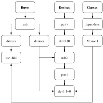
The Linux kernel supports device hotplugging, and is permanently alert to hardware changes in the system. This information collected by the kernel is transformed into an object-oriented representation of the system, the device model, structured similarly to the example in Fig-ure 3.2. The current device model design dates back to the Linux’s 2.5 development cycle, and it is exposed to the userspace as a memory-based virtual filesystem, sysfs, mounted at the /sys directory.
Buses Devices usb drivers devices usb−hid pci() dev0:10 usb2 port1 dev1:1−0 Classes Input devs Mouse 1
Figure 3.2: Linux device model.
A fundamental structure of the device model is the kobject. Just as the name points out, it is the base representation for a kernel object. When exported to the userspace, every item in the sysfs file tree has an underlying kobject that binds the structures to the kernel. Any direct manipulation of a kobject is automatically updated in the sysfs tree. sysfs entries for kobjects are always directories. Each kobject also exports one or more attributes. An attribute has a name (key), value, and an associated module responsible for its implementation. Each at-tribute results in a sysfs file with the same name; reads and writes to the file translate in calls to the show and store methods of its module, respectively. From a higher level perspective, directories become objects, files become attribute keys, and file contents become attribute val-ues. So, for example, /sys/class/net/wlan0/address contains 00:11:22:33:44:55, which
is the value of the attribute address from the object wlan0.
Although it was initially to facilitate debugging, sysfs (formerly debugfs) became a re-placement for ioctl [35]. There are limitations to this: sysfs conventions call for all attributes to contain a single value in a human readable text format, which makes the mechanism unsuit-able for large data transfers, while also being limited to text-based interfaces. Moreover, the model does not directly support event signaling for userspace applications, and notifications have to be handled through separate frameworks. A different solution to replace ioctl was accepted in early Linux 2.0, based on sockets, called Netlink.
3.1.3 Netlink sockets
There is a large number of socket implementations, with varying types and domain scopes (or address families). Every socket implementation provides at least two types: stream and datagram [37]. Stream sockets operate in connected pairs and provide a reliable, bidirectional, byte-stream communication channel. Datagram sockets are connectionless and transfer data in separate messages, called datagrams, without any guarantee of delivery.
A socket domain specifies how a socket is addressed, as well as the scope of the com-munication. Common domains include AF_UNIX, which uses file system paths for addressing within the same machine, and AF_INET/AF_INET6 for communication over the IPv4 and IPv6 Internet domains, respectively. In the Internet domain, datagram sockets employ the User Datagram Protocol and stream sockets employ the Transmission Control Protocol.
A socket is created with the socket() syscall. The bind(), method assigns it an address and the methods send() and recv() are then used to exchange information:
# i n c l u d e < sys / t y p e s . h > # i n c l u d e < sys / s o c k e t . h >
int s o c k e t ( int domain , int type , int p r o t o c o l ) ;
int b i n d ( int sockfd , c o n s t s t r u c t s o c k a d d r * addr , s o c k l e n _ t a d d r l e n ) ; s s i z e _ t s e n d ( int sockfd , c o n s t v o i d * buf , s i z e _ t len , int f l a g s ) ; s s i z e _ t r e c v ( int sockfd , v o i d * buf , s i z e _ t len , int f l a g s ) ;
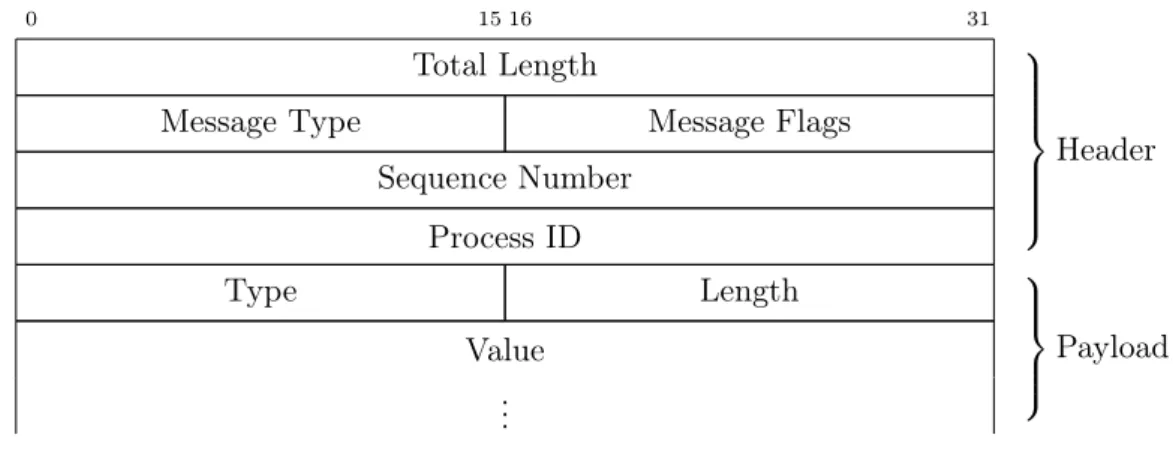
Netlink [38] is a datagram-oriented message system1. It allows message passing between the kernel and userspace, but also among user-space processes, for Inter-Process Communica-tion. Netlink sockets are addressed in the AF_NETLINK domain, which is similar to AF_UNIX, but depends on Process IDs (PIDs) for addressing rather than file system paths. The protocol messages consist of a header, shown in Figure 3.3, and the additional payload attached to it. Large messages may be split into multiple datagrams; message ordering is not guaranteed, but the Sequence Number and Flags fields allow correct reconstruction of the payload at the destination.
Each Netlink protocol (family) defines their own message format to fill the payload, usu-ally employing a stream of Type-Length-Value (TLV) attributes. The TLV format allows
1
Netlink sockets support both SOCK_RAW (for raw network protocol access) and SOCK_DGRAM types, but no distinction is made between the two.
3.1. KERNEL/HARDWARE INTERFACING 17
0 15 16 31
Total Length
Message Type Message Flags Sequence Number Process ID Header Type Length Value .. . Payload
Figure 3.3: Netlink message format.
the addition of new attributes without breaking backward compatibility of existing appli-cations [39]. Extending a protocol simply requires adding new attributes and updating the user-space application to support it; applications that do not support an attribute skip it, and the rest of the implementation remains intact1. This results in higher flexibility than either ioctl or sysfs solutions.
There are two communication types for a Netlink bus: unicast and multicast. Unicast is used for one to one communication; typically to send commands or queries from user to kernel-space, and receive their corresponding response. Multicast is a one to many communication channel, and is typically used by the kernel for event notifications; in fact, device model events, referred in Section 3.1.2, are propagated through Netlink.
Netlink supports up to 32 buses2 in kernel space, each attached to one kernel subsystem, although several subsystems could share the same bus [39]. As of writing, this listing is supported:
• NETLINK_ROUTE can be used to modify routing tables and IP addresses both for IPv4 and IPv6, as well as changing link attributes, queuing disciplines, packet classifiers, etc. It is also used for broadcasting routing and link updates.
• NETLINK_FIREWALL and NETLINK_IP6_FW are used to transfer packets from netfilter, the Linux’s packet filtering framework, to the userspace.
• NETLINK_NETFILTER serves as the interface for the netfilter framework, for packet mangling across each specific protocol stack.
• NETLINK_XFRM, for communication with the kernel module that handles Security Associations and Security Policies for Internet Protocol Security (IPsec) in Linux. • NETLINK_USERSOCK, for user space socket protocols.
• NETLINK_W1, for the 1-wire subsystem.
1
Removing or changing attributes will break implementations that depend on them.
2
• NETLINK_ISCSI, for Open-iSCSI.
• NETLINK_INET_DIAG, for INET socket monitoring. • NETLINK_NFLOG, for Netfilter/iptables ULOG. • NETLINK_SELINUX, for SELinux event notifications.
• NETLINK_AUDIT, for auditing, as a complement to SELinux.
• NETLINK_FIB_LOOKUP, to lookup Forward Information Base entries. • NETLINK_CONNECTOR, for the special kernel connector driver. • NETLINK_DNRTMSG, for DECnet routing messages.
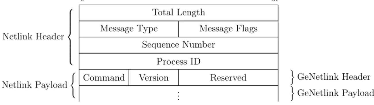
• NETLINK_KOBJECT_UEVENT, for device model notifications to the userspace. Given the concern that the number of Netlink family numbers might exhaust in the near future, an additional family was created: NETLINK_GENERIC. Generic Netlink acts as a Netlink multiplexer, allowing multiple interfaces on a single Netlink bus. Family IDs for new interfaces are created and discovered at runtime, based on text names. Generic Netlink are encapsulated in the Netlink payload as shown in Figure 3.4.
0 31
Total Length
Message Type Message Flags Sequence Number Process ID Netlink Header
Command Version Reserved
o GeNetlink Header .. . Netlink Payload ( o GeNetlink Payload
Figure 3.4: Generic Netlink Message format.
For network managing purposes, Route Netlink (NETLINK_ROUTE) and a specific in-terface on Generic Netlink, nl80211, are of great importance, and will be now further extended. 3.1.3.1 Route Netlink
Route Netlink is considered the most mature of all the Netlink family protocols [40]. The protocol itself can be subdivided into classes, with specific messages, each of which interfacing with a specific part of the Linux kernel’s network routing system in the following list:
• LINKS: create, remove or get information about a specific network interface.
• ADDRESSES: add, remove or receive information about an address associated to an interface.
3.1. KERNEL/HARDWARE INTERFACING 19
• ROUTES: create, remove or receive information about a network route.
• NEIGHBORS: add, remove or receive information about a neighbor table entry. • RULES: add, delete or retrieve a routing rule.
• DISCIPLINES: add, remove or get a queuing discipline. • CLASSES: add, remove or get a traffic class.
• FILTERS: add, remove or receive information about a traffic filter.
Each class defines an ancillary data type for the messages, and is optionally followed by a set of subsequent attributes of varying length. These data types define the operations on a set of objects that can be represented as a table. There are three primitives for operation on those tables:
• GET, to retrieve entries in the table. • NEW, to create or edit table entries. • DEL, to delete table entries.
For the GET message, most of these fields may be set to an unspecified value, to act like wildcards, or they can be specified to filter results. NEW and DEL messages may be used as commands, but are also commonly available as multicast messages for notifications on certain groups.
For the scope of this dissertation, the purpose of the LINK, ADDR and ROUTE message classes are particularly relevant, and will be presently explained.
The LINK messages
The LINK family of messages allows a user of the Route Netlink protocol to manipulate information about network interfaces on the system. Each underlying entry on the LINK table refers to a network interface that exists on the computer, whether physical or virtual. The three LINK message types are:
• RTM_NEWLINK: create or edit network interfaces. • RTM_DELLINK: destroy network interfaces.
• RTM_GETLINK: retrieve information about network interfaces.
The NEW and DEL messages may be transmitted as notifications on the RTMGRP_LINK multicast group of the Route protocol; the NEW message indicates a link creation or link parameter changes, and the DEL message indicates a link removal. The ancillary data type for the LINK messages is defined as follows:
# i n c l u d e < l i n u x / r t n e t l i n k . h > s t r u c t i f i n f o m s g { u n s i g n e d c h a r i f i _ f a m i l y ; u n s i g n e d s h o r t i f i _ t y p e ; int i f i _ i n d e x ; u n s i g n e d int i f i _ f l a g s ; u n s i g n e d int i f i _ c h a n g e ; };
• ifi_family: set to AF_UNSPEC, except for interfaces with associated IPv6 addresses, in which case the field is AF_INET6.
• ifi_type: the interface type, supporting various wired and wireless technologies. • ifi_index: unique identifier of the interface in the system. It is not statically associated
with the hardware and may vary at each system boot or configuration changes. • ifi_flags: the interface flags, used to define an interface’s power state, for example. • ifi_change: reserved for future use, currently set to 0xFFFFFFFF.
In each message, this structure should be followed by additional attributes, including the interface’s physical address, its MTU the label of the interface in the system, statistics data, etc.
The ADDR messages
Route Netlink ADDR messages refer to the manipulation of IP addresses in the network interfaces. It is composed as well by a group of three message types:
• RTM_NEWADDR: add or edit interface addresses. • RTM_DELADDR: remove addresses from an interface. • RTM_GETADDR: get addresses from interfaces.
These messages support IPv4 and IPv6 addresses, and an interface can be assigned mul-tiple IP addresses (previously this was only achieved with alias devices). Much like in the LINK messages scenario, it is possible to subscribe to a multicast channel that will generate RTM_NEWADDR and RTM_DELADDR to announce changes to the address table of each network interface. Every ADDR message contains the following structure:
# i n c l u d e < l i n u x / r t n e t l i n k . h >
s t r u c t i f a d d r m s g {
u n s i g n e d c h a r i f a _ f a m i l y ; u n s i g n e d c h a r i f a _ p r e f i x l e n ;
3.1. KERNEL/HARDWARE INTERFACING 21
u n s i g n e d c h a r i f a _ f l a g s ; u n s i g n e d c h a r i f a _ s c o p e ; int i f a _ i n d e x ;
};
• ifa_family: the address family to which this address belongs. This is currently limited to AF_INET and AF_INET6.
• ifa_prefixlen: the length of the address mask of this address.
• ifa_flags: properties of this address. Whether this is a primary or secondary address for the interface, permanent or temporary, etc.
• ifa_scope: the scope of the address, such as link-local (RT_SCOPE_LINK), site-local (RT_SCOPE_SITE) or global (RT_SCOPE_UNIVERSE). Two additional scopes are available, for addresses limited to host boundaries (RT_SCOPE_HOST) and a special case “nowhere” (RT_SCOPE_NOWHERE).
• ifa_ifindex: the interface this address is associated with. This may be regarded as a foreign key to the LINK table, as this value uniquely identifies a LINK object.
ADDR messages may also carry additional attributes regarding the address itself (such as the associated local, broadcast and anycast addresses), or the interface it is associated with (its interface name or mac address).
The ROUTE messages
These messages baptize the protocol name and, as it points out, they refer to IP routing table management. Without exception, there are three message types:
• RTM_NEWROUTE: create or edit routes.
• RTM_DELROUTE: remove routes or notify of route removal. • RTM_GETROUTE: get existing configured routes.
The underlying data type is the rtmsg, declared as follows:
# i n c l u d e < l i n u x / r t n e t l i n k . h > s t r u c t r t m s g { u n s i g n e d c h a r r t m _ f a m i l y ; u n s i g n e d c h a r r t m _ d s t _ l e n u n s i g n e d c h a r r t m _ s r c _ l e n ; u n s i g n e d c h a r r t m _ t o s ; u n s i g n e d c h a r r t m _ t a b l e ; u n s i g n e d c h a r r t m _ p r o t o c o l ; u n s i g n e d c h a r r t m _ s c o p e ;
u n s i g n e d c h a r r t m _ t y p e ; u n s i g n e d int r t m _ f l a g s ; };
• rtm_family: similar to the ifa_family field in ADDR messages.
• rtm_dst_len: the length of the destination address of the route entry, included in the additional message attributes.
• rtm_src_len: the length of the source address of the route entry, included in the additional message attributes.
• rtm_tos: the Type of Service (TOS) indicator for the route. This makes use of the TOS header field in the IPv4 header, replaced by the traffic class field in IPv6.
• rtm_table: specifies the routing table ID. Can be default (RT_TABLE_DEFAULT), main (RT_TABLE_MAIN) or local (RT_TABLE_LOCAL).
• rtm_protocol: how the route originated. Possible values are RTPROT_KERNEL, if originated by the kernel; RTPROT_REDIRECT if originated by an ICMP redirect; RTPROT_BOOT during boot and RTPROT_STATIC if set by the administrator. • rtm_scope: pertains to the scope of the destination, with values ranging similarly to
the ifa_scope field of ADDR messages.
• rtm_type: the type of this route. Possible values include RTN_UNREACHABLE, RTN_UNICAST, RTN_LOCAL, RTN_BROADCAST and RTN_ANYCAST. • rtm_flags: various extra parameters for a route.
Just like with other messages, ROUTE messages may require several additional attributes, such as:
• RTA_DST: the route destination address. • RTA_SRC: the route source address. • RTA_IIF: the input interface index. • RTA_OIF: the output interface index.
• RTA_GATEWAY: the default gateway of the route. • RTA_PRIORITY: the priority of this route.
• RTA_PREFSRC: the preferred source address for an IPv6 route. • RTA_METRICS: the route cost metric.
3.1. KERNEL/HARDWARE INTERFACING 23
Summary
The Linux network subsystem exposed by the Route Netlink protocol is significantly larger than the subset presented in this subsection. As mentioned before, it also allows the config-uration of neighbor (Address Resolution Protocol (ARP)) tables, routing rules, traffic classes and filters, and queuing disciplines. These fall out of basic network managing processes and are not further documented here. For an extensive analysis of this protocol, section 7 of the “rtnetlink” GNU/Linux manpage can be consulted.
3.1.3.2 nl80211
Several aspects of a network interface can be manipulated by the Route Netlink kernel in-terface, but there is a very wide range of variables to take into account for an IEEE 802.11 interface that the routing subsystem is not aware of. In essence, there is a whole different kind of interface that the kernel needs to expose to the userspace in order to support wireless network management.
Traditionally, the WLAN Application Programming Interface (API) for Linux was Wireless Extensions (WEs)1, developed by Jean Tourrilhes and sponsored by Hewlett Packard2. This
framework is still used, but it is based on ioctl calls, so it is being deprecated in light of the advantages of Netlink. nl80211 operates on the Generic Netlink bus and since its beginning in 2006, together with cfg80211, aims at replacing the WEs [41]. It is still a work in progress; current IEEE 802.11 drivers still support the WEs, but it is already the recommended archi-tecture for new applications being developed. Interpreting Figure 3.5, the real interface for IEEE 802.11 drivers is cfg80211, and nl80211 are just different userspace endpoints for that interface, both for Station and AP applications.
userspace
cfg80211 mac80211
nl80211 WEs
Figure 3.5: Linux Wireless layered interface.
Unlike the Route Netlink protocol, the interface fails to follow a strict model of categorized messages, and instead relies on a series of disparate commands and parameters to carry out a large array of operations, which can be roughly grouped in the categories of the following sections.
1
Wireless Extensions, http://www.hpl.hp.com/personal/Jean_Tourrilhes/Linux/Tools.html
2
Wireless interface management
nl80211 allows getting and setting many interface attributes, and handling virtual interfaces. There are four CMD_<OP>_WIPHY and CMD_<OP>_INTERFACE, where <OP> stands for one of GET, SET, NEW or DEL.
WIPHY objects correspond to a physical wireless device in the system. Physical devices are not created or deleted from userspace, this takes place at kernel level, according to sup-ported devices and device drivers. The DEL_WIPHY command is used as a notification that a physical IEEE 802.11 device was removed from the device model1; the NEW_WIPHY command is used as a notification that a new physical device is available, as a notification of a rename, or as a response to a GET_WIPHY request. With the GET_WIPHY request one can retrieve a list of available devices, or a very extensive list of hardware attributes and capabilities (supported frequency bands, authentication mechanisms, etc), as well as a list of accepted commands and interface modes (Infrastructure, IBSS, etc). The SET_WIPHY command allows the configuration of transmission power, transmission queue parameters, antenna selection and some threshold and retry parameters.
Each WIPHY can hold many virtual interfaces, created with the NEW_INTERFACE command. Virtual interfaces define roles for the underlying WIPHY (Station, AP, Mesh Point, etc). Usually there is a single virtual interface on top of the physical hardware due to the fact that not all devices are able to operate with virtual MAC addresses, and also because concurrent operating modes may face a number of restrictions. Device drivers commonly define a default INTERFACE for a WIPHY object and allow further modifications, if they support other operation modes (but support for changing modes at runtime is not mandatory). The NEW command may also be used to notify of newly created virtual interfaces, and as a reply to GET_INTERFACE requests for, retrieving an interface’s configuration. Finally, SET_INTERFACE is used to change the type of an existing interface.
Power management
Other than ON/OFF, the IEEE 802.11 interfaces implement power options described by the standard, such as letting the device sleep between beacons from the AP. This behavior can be enabled or disabled through the SET_POWER_SAVE command. Checking the current configuration is done with the GET_POWER_SAVE command.
The Linux kernel also supports various enablers for the non-standard “Wake on WLAN” feature. This feature is supported while connected to a network, based on triggers like the reception of a user specified pattern, a magic packet [42], or disconnection from an AP. While disconnected from a network, a trigger such as the discovery of a new network can be used. The list of supported triggers for each device is available in the WIPHY properties and through the GET_WOWLAN command. To activate a trigger, the SET_WOWLAN command is used.
1
This could be either because the network hardware is physically removed or simple because the driver module was removed from the running kernel.