Universidade de Aveiro Departamento deElectr´onica, Telecomunica¸c˜oes e Inform´atica 2013
Nuno Miguel Vicente
Ruivo Nunes
Adapta¸
c˜
ao da Taxa de Transmiss˜
ao em Redes
‘’
—
Universidade de Aveiro Departamento deElectr´onica, Telecomunica¸c˜oes e Inform´atica 2013
Nuno Miguel Vicente
Ruivo Nunes
Adapta¸
c˜
ao da Taxa de Transmiss˜
ao em Redes
Universidade de Aveiro Departamento deElectr´onica, Telecomunica¸c˜oes e Inform´atica 2013
Nuno Miguel Vicente
Ruivo Nunes
Adapta¸
c˜
ao da Taxa de Transmiss˜
ao em Redes
Veiculares
Disserta¸c˜ao apresentada `a Universidade de Aveiro para cumprimento dos requesitos necess´arios `a obten¸c˜ao do grau de Mestre em Engenharia Electr´onica e Telecomunica¸c˜oes, realizada sob a orienta¸c˜ao cient´ıfica da Doutora Susana Isabel Barreto de Miranda Sargento e do Doutor Arnaldo Silva Rodrigues de Oliveira, professores auxiliares do Departamento de Electr´onica, Telecomunica¸c˜oes e Inform´atica da Universidade de Aveiro.
o j´uri / the jury
presidente / president Prof. Doutor Paulo Miguel Nepomuceno Pereira Monteiro
Professor Associado do Departamento de Electr´onica, Telecomunica¸c˜oes e In-form´atica da Universidade de Aveiro
vogais / examiners committee Prof. Doutora Susana Isabel Barreto de Miranda Sargento
Professora Auxiliar do Departamento de Electr´onica, Telecomunica¸c˜oes e In-form´atica da Universidade de Aveiro
Prof. Doutora Teresa Maria S´a Ferreira Vaz˜ao Vasques
agradecimentos / acknowledgements
Em primeiro lugar, gostaria de agradecer aos meu pais e `a minha fam´ılia pelo incans´avel apoio durante todo o meu percurso acad´emico. Quero agradecer tamb´em aos meus amigos, pois sempre estiveram presentes nos momentos mais dif´ıceis. Um especial agradecimento `a Professora e presente orienta-dora Susana Sargento, por me ter oferecido a possibilidade de realizar esta Disserta¸c˜ao, bem como toda a orienta¸c˜ao prestada ao longo da mesma. Por fim agrade¸co a todos aqueles que me ajudaram a realizar esta Disserta¸c˜ao, em especial ao Tom´e Gomes.
Resumo Ao longo dos ´ultimos anos, v´arios progressos em comunica¸c˜oes sem fios tˆem extendido investiga¸c˜oes a novas ´areas, onde solu¸c˜oes baseadas em re-des com fios s˜ao impratic´aveis. Neste contexto apareceram as Vehicular Ad hoc NETworks (VANETs), uma classe emergente das redes Ad Hoc, para interliga¸c˜ao e comunica¸c˜ao entre ve´ıculos. Devido `as suas caracter´ısticas peculiares como alta mobilidade, topologia dinˆamica, frequente perda de conectividade, as VANETs enfrentam v´arios desafios para definir protolocos e mecanismos fi´aveis, como a adapta¸c˜ao da taxa de transmiss˜ao. De facto, a monitoriza¸c˜ao do tr´afego das ruas atrav´es de aplica¸c˜oes s˜ao o n´ucleo das VANETs cujo desempenho depende da taxa de envio de pacotes e da taxa de sucesso que estas redes conseguem oferecer. Mecanismos de adapta¸c˜ao da taxa de transmiss˜ao tˆem como objetivo evitar a degrada¸c˜ao do desempenho da rede devido a uma escolha muito elevada da taxa de transmiss˜ao, quando a qualidade do canal est´a deteorada, ou devido `a utiliza¸c˜ao de uma taxa muito baixa quando as condi¸c˜oes da qualidade do canal melhoram. Uma vez que os dispositivos que operam segundo a norma IEEE 802.11p supor-tam v´arias taxas de transmiss˜ao, ´e importante que estes possam adaptar a taxa de forma dinˆamica de modo a obter um desempenho elevado. As-sim ´e essencial ter um mecanismo de adapta¸c˜ao da taxa de transmiss˜ao que seja robusto e capaz de lidar com elevadas flutua¸c˜oes e assimetrias do canal, transmiss˜oes em rajada e de dura¸c˜ao inconstante, e perda de pacotes devido `
as condi¸c˜oes do meio e `a existˆencia de terminais escondidos. Assim sendo, esta disserta¸c˜ao permite avaliar e comparar os mecanismos existentes para redes sem fios, em ambientes veiculares usando o Network Simulator 3 (NS-3) e o Simulator of Urban Mobility (SUMO). Depois de analisar os principais mecanismos presentes na literatura, foram selecionados quatro para serem testados: Adaptive Auto Rate Fall Back-Collision Detection (AARF-CD), Collision-Aware Rate Adaptation (CARA), Minstrel e o Ideal. Ser˜ao con-siderados dois tipos de cen´arios: auto-estrada e urbano. A compara¸c˜ao dos algoritmos ser´a baseada em m´etricas conhecidas como a taxa de envio de pacotes, taxa de sucesso e a percentagem de retransmiss˜oes para v´arios n´ıveis de transmiss˜ao. Os resultados experimentais mostraram que o AARF-CD atingiu um desempenho superior, quando comparado com os restantes algoritmos. O CARA foi o segundo melhor algoritmo segundo as m´etricas consideradas. De real¸car que o AARF-CD obteve uma taxa de sucesso su-perior ao do CARA, apesar deste oferecer uma taxa de envio de pacotes superior em certos cen´arios. Em rela¸c˜ao ao atraso na rede, tanto o AARF-CD como o CARA alcan¸caram resultados similares. Foi tamb´em conclu´ıdo que algoritmos com diferencia¸c˜ao de perdas de pacotes como o AARF-CD e o CARA oferecem uma melhor adapta¸c˜ao da taxa de transmiss˜ao. Por fim, ´e sugerido um algoritmo de adata¸c˜ao da taxa de transmiss˜ao que tem em conta parˆametros externos, como a velocidade, distˆancia e a densidade de ve´ıculos. Cada parˆametro ´e considerado de acordo com a sua influˆencia na transmiss˜ao de dados atrav´es de pesos. Desta forma os parˆametros que afetam mais a adapta¸c˜ao da taxa de transmiss˜ao ser˜ao associados a pesos maiores. A adata¸c˜ao da taxa de transmiss˜ao ser´a baseada num processo de pesos, de acordo com o efeito das condi¸c˜oes exteriores no desempenho da
Abstract Over the last years, several progresses in wireless communications have ex-tended research in new sub-areas, where wired solutions are impracticable. In this context, VANETs arose as an emerging area of wireless ad hoc networks, which connect and allow communication between vehicles. Due to its peculiar characteristics such as high mobility, dynamic topology and frequent loss of connectivity, VANETs face many challenges to define reli-able protocols and mechanisms like rate adaptation schemes. Indeed traffic querying and road sensing applications are the core of VANETs whose per-formance depends on the throughput and the success ratio these networks can provide. Rate adaptation mechanisms aim to avoid performance net-work degradation due to rate over-selection when channel quality is deteri-orated or rate under-selection when channel quality improves. Since IEEE 802.11p supports multi-rate capabilities, devices must adapt their trans-mission rate dynamically in order to achieve a high performance. Thus it is critical to have a robust rate adaptation mechanism that can deal with high fluctuation and asymmetry of channels, bursty and infrequent duration transmissions, and loss packet own to the extreme environment conditions or hidden terminals. Thereby, this dissertation evaluates and compares the existing rate adaptation mechanisms for wireless in vehicular environments, using NS-3 and SUMO. Four mechanisms: AARF-CD, CARA, Minstrel and Ideal were selected to be compared, after analysing the main mechanisms across literature. It will be considered two types of scenarios: highway and urban scenario. The comparison between the algorithms will be based on known metrics: network throughput, success ratio, delay and percentage of retransmissions. Experimentation results showed that AARF-CD achieved higher performance when compared with the remaining algorithms in both scenarios. CARA was the second best algorithm, considering the same met-rics. Although CARA provides higher throughput in certain scenarios, it is outperformed by AARF-CD in terms of rate success. Regarding delay, AARF-CD and CARA attained similar results. It was also concluded that algorithms with loss differentiation such as AARF-CD and CARA provide better rate adaptation. Finally, it is suggested a rate adaptation algorithm which considers external parameters like velocity, distance and density of nodes. Each parameter is considered according to its impact in the data transmission through weights. Parameters that affect more the rate adap-tation are associated to larger weights. Thus, the rate adapadap-tation is based on a weighted process according to the effect of external conditions in the network performance.
Contents
Contents i
List of Figures v
List of Tables vii
Acronyms viii 1 Introduction 1 1.1 Motivation . . . 1 1.2 Objectives . . . 2 1.3 Contributions . . . 3 1.4 Document organization . . . 4 1.5 Summary . . . 4 2 Vehicular Networks 5 2.1 Introduction . . . 5
2.2 What are VANETS? . . . 5
2.3 Basic concepts . . . 6 2.3.1 Specific features . . . 7 2.3.2 Equipment . . . 7 2.4 Technical challenges . . . 8 2.5 Network architecture . . . 9 2.6 Data dissemination . . . 10
2.7 Network access technology . . . 12
2.7.1 WAVE standard . . . 12
2.7.2 IEEE 802.11p . . . 13
2.7.2.1 MAC layer . . . 14
2.7.2.2 PHY layer . . . 15
2.8 Applications and services . . . 16
2.8.1 Safety applications . . . 17
2.8.1.1 Cooperative Collision Avoidance . . . 17
2.8.1.2 Emergency Warning Messages . . . 18
2.8.2 Monitoring and management applications . . . 19
2.8.3 Comfort applications . . . 19
3 Data Rate Adaptation in wireless Networks 21
3.1 Introduction . . . 21
3.2 What are Rate Adaptation Mechanisms? . . . 21
3.2.1 Techniques . . . 22
3.3 Algorithms without loss differentiation . . . 23
3.3.1 Frame loss approach . . . 24
3.3.2 Signal-to-Noise Ratio (SNR) approach . . . 25
3.4 Algorithms with loss differentiation . . . 26
3.5 VANET simulation . . . 30 3.5.1 Network simulators . . . 31 3.5.2 Mobility simulator . . . 32 3.6 Summary . . . 33 4 Scenario implementation 35 4.1 Introduction . . . 35 4.2 Simulation platform . . . 35 4.3 Wifi model . . . 36
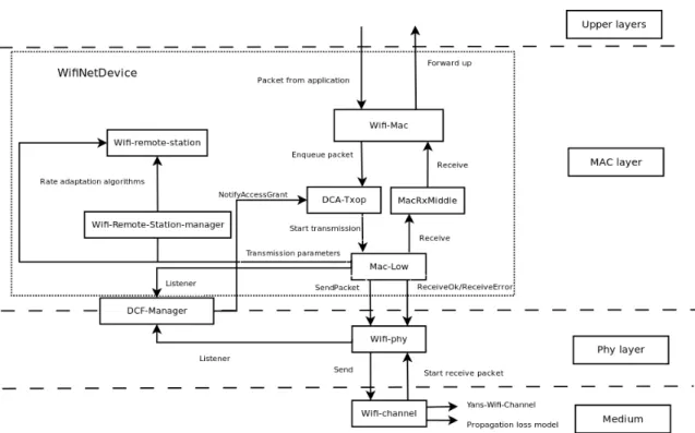
4.3.1 Medium Access Control (MAC) model . . . 37
4.3.2 Phy model . . . 39
4.3.3 Channel Model . . . 39
4.4 Scenario architecture . . . 39
4.4.1 User Datagram Protocol (UDP) sessions . . . 40
4.4.2 Address Internet Protocol (IP) and protocol stack . . . 40
4.4.3 Routing protocol . . . 41
4.4.4 Mobility . . . 41
4.4.5 Propagation Loss model . . . 41
4.4.6 Rate adaptation . . . 42 4.4.6.1 AARF-CD . . . 43 4.4.6.2 CARA . . . 44 4.4.6.3 Ideal . . . 46 4.4.6.4 Minstrel . . . 47 4.4.7 Transmission parameters . . . 48
4.4.7.1 Data packet identification . . . 48
4.4.7.2 Current data rate . . . 49
4.4.7.3 Received Signal Strength Indicator (RSSI) and Node ID . . . 50
4.4.7.4 Transmitted and received packets . . . 51
4.4.7.5 Retransmissions . . . 51
4.4.8 Performance metrics . . . 51
4.4.8.1 Average end-to-end packet delay . . . 52
4.4.8.2 Throughput . . . 52
4.4.8.3 Success ratio . . . 52
4.4.9 Simulated scenarios . . . 52
4.5 Challenges . . . 54
5 Simulation results 57 5.1 Introduction . . . 57 5.2 Scenarios . . . 57 5.3 Global evaluation . . . 59 5.3.1 Highway scenario . . . 61 5.3.1.1 Density . . . 61 5.3.1.2 Velocity . . . 61 5.3.1.3 Distance . . . 64 5.3.2 Urban scenario . . . 66 5.3.2.1 Density . . . 66 5.3.3 Proposed solution . . . 67 5.3.4 Summary . . . 68
6 Conclusion and future work 70 6.1 Conclusion . . . 70
6.2 Future work . . . 71
List of Figures
2.1 Intelligent transport system in [1] . . . 6
2.2 VANETs architecture in [2] . . . 9
2.3 Car-to-Car Communication Consortium architecture in [3] . . . 10
2.4 Single-hop/broadcast and multi-hop/unicast data dissemination in scheme (a) and (b) respectively [4] . . . 12
2.5 Wireless Access Vehicular Environments (WAVE) architecture in [5] . . . 13
2.6 Multipah physical environments [6] . . . 14
2.7 Basic service set concept in [7] . . . 15
2.8 Safety application in [4] . . . 18
2.9 Permanent geocasting in [4] . . . 19
4.1 NS-3 architecture - [8] . . . 36
4.2 802.11 implementation in NS-3 . . . 37
4.3 AARF-CD algorithm flowchart . . . 43
4.4 Cara algorithm flowchart . . . 45
4.5 Ideal algorithm flowchart . . . 46
4.6 Minstrel algorithm flowchart . . . 47
4.7 Tag data packets . . . 49
4.8 Record information in data packets . . . 50
4.9 Tag RSSI and transmiter’s ID . . . 50
4.10 Record retransmissions number . . . 51
5.1 Mobility traces schemes . . . 58
5.2 Delay for different data traffic rate schemes . . . 60
5.3 Comparison between rate adaptation mechanisms for highway scenario, v=5m/s 62 5.4 Comparison between rate adaptation mechanisms for highway scenario, v=11m/s 63 5.5 Comparison between rate adaptation mechanisms for highway scenario, v=25m/s 63 5.6 Comparison between rate adaptation mechanisms for highway scenario, d=100m 64 5.7 Comparison between rate adaptation mechanisms for highway scenario, d=200m 65 5.8 Comparison between rate adaptation mechanisms for highway scenario, d=300m 66 5.9 Comparison between rate adaptation mechanisms for urban scenario . . . 67
5.10 Process to obtain the optimal weights . . . 68
List of Tables
2.1 80211p and 80211a Physical (PHY) values, adapted from [9] . . . 16
2.2 Minimum receiver sensitivity per data rate adapted from [10] . . . 17
3.1 Multi-rate retry chain used by minstrel in [11] . . . 25
3.2 Features of rate adaptation mechanisms adapted from [12] . . . 27
4.1 Parameters used in AARF-CD . . . 44
4.2 Parameters used in CARA . . . 46
4.3 Simulated scenario attributes . . . 53
4.4 Command variables meaning to execute one simulation . . . 54
5.1 Symbolic notation of data rates . . . 60
5.2 AARF-CD adaptation considering 200m scheme and 16 nodes of each distance scheme . . . 65
Acronyms
4G Fourth Generation of cellular wireless standards AP Access Point
AU Application Unit
AODV Ad hoc On-Demand Distance Vector ACK ACKnowledgment
ARF Auto Rate Fallback
AARF Adaptive Auto Rate Fallback
AGILE Ack-Guide Immediate Link rate Estimation
AARF-CD Adaptive Auto Rate Fall Back-Collision Detection AU Application Unit
AMRR Adaptive Multi Rate Retry BER Bit Error Rate
BSS Basic Service Set
BSSID Basic Service Set Identification
C2C-CC Car-to-Car Communication Consortium CCH Control Channel
CSMA Carrier Sense Multiple Access CTS Clear To Send
CCA Clear Channel Assessment
CARA Collision-Aware Rate Adaptation CARS Context-Aware Rate Selection CCA Cooperative Collision Avoidance CHARM Channel-Aware Rate Adaptation
DSRC Dedicated Short-Range Communications DCF Distributed Coordination Function
DAD Duplicate Address Detection
EWMA Exponential Weighted Moving Average EWM Emergency Warning Message
FCC Federal Communications Commision GPS Global Positioning System
GPRS General Packet Radio Service
GSM Global System for Mobile communications IEEE Institute of Electrical and Electronics Engineers ITS Intelligent Transportation System
IP Internet Protocol ID IDentifier
LTE Long-Term Evolution LOS Line-of-Sight
LLC Logical Link Control
LWMA Linear Weighted Moving Average MAC Medium Access Control
MANET Mobile Ad Hoc Network NS-3 Network Simulator 3
NS-2 Network Simulator 2 NLOS Non-Line-Of-Sight
OEM Original Equipment Manufacture OBU On-Board Unit
OLSR Optimized Link State Routing OSI Open Systems Interconnection
OFDM Orthogonal Frequency-Division Multiplexing PHY Physical
QoS Quality of Service RSU Road Side Unit RTS Request To Send
RSSI Received Signal Strength Indicator RAM Rate Adaptation in Mobile environments RRAA Robust Rate Adaptation Algorithm RBAR Receiver-Based AutoRate
SUMO Simulator of Urban Mobility
STDMA Self organized Time Division Multiple Access SNR Signal-to-Noise Ratio
SSID Service Set IDentification SCH Service Channel
TCP Transmission Control Protocol UDP User Datagram Protocol
UMTS Universal Mobile Telecommunications System UWB Ultra-WideBand
VANET Vehicular Ad hoc NETwork V2V Vehicle-to-Vehicle
V2I Vehicle to Infrastructure
WAVE Wireless Access Vehicular Environments WLAN Wireless Local Access Network
WIMAX Worldwide Interoperability for Microwave Access Wi-Fi IEEE 802.11 a/g/n
WSMP WAVE mode Short Message Protocol WUSB Wireless USB
WBSS WAVE Basic Service Set ZOR Zone-Of-Relevance
Chapter 1
Introduction
This document, denoted as ”rate adaptation mechanisms in vehicular networks”, presents the accomplished work during the dissertation concerning to the master in Electronics and Telecommunications Engineering in the department of Electronic, Telecommunication and Informatic of university of Aveiro.
This work aims to analyse and take a step further towards rate adaptation mechanisms in vehicular networks.
In this chapter it is explained the motivation associated to this work, proposed objectives and a brief description of its structure.
1.1
Motivation
Nowadays vehicular networks have been deeply investigated by several entities. They gather efforts to build a solid network to share information between vehicles, increasing road safety. Drivers could be warned about traffic jams, accidents or other types of alerts. There-fore, it is expected that all vehicles will communicate between them, and consequently take decisions according to the received information such as security and alarm messages. Beyond security information, these networks can address other applications in which dissemination of information could be based in interactive games or social networking.
The main purpose of research in VANETs is to investigate how communication between vehicles can improve user experience, increase security and connect all the elements of a road to the same network.
These networks, known as VANETs, are formed by dynamic nodes with high and un-predictable mobility, the vehicles. VANETs experience often lack of nodes in the network, leading to periods without communication between vehicles, once they do not have vehicles in their range. All this interaction depends on the set of parameters that determine their velocity and position. Vehicles form dynamic clusters which suffers many changes in their topology according to vehicles density and mobility.
Many factors such as velocity, density, position and distance cause undesirable results which are intolerable to this type of network. For example high delays or low throughputs can compromise network performance.
Data rate adaptation is one of the key mechanism at MAC layer in order to control data communications. It evaluates and decides which rate should be applied at the physical layer for communication.
Several rate adaptation mechanisms based on different techniques have been deployed for Wi-Fi networks. However vehicular environments cannot be considered as a traditional Wi-Fi network. In those networks, devices experience high interference and channel instability and asymmetry. New standards and technologies were developed to face these new challenges, intrinsic to VANETs.
In the near future, the number of communications among vehicles will increase using WAVE and Dedicated Short-Range Communications (DSRC) infrastructures [13]. Actually, the Federal Communications Commision (FCC) has reserved a DSRC spectrum to improve bandwidth and minimize latency in Vehicle-to-Vehicle (V2V) and Vehicle to Infrastructure (V2I) communication. Many applications can be run in vehicular networks, exchanging differ-ent types of messages; however, some of them require a high level of communication reliability to succeed. Low delays and high throughputs have to be guaranteed even in hostile and dy-namic environments with unstable link conditions.
Thus, devices have to react dynamically through appropriate mechanisms to establish communications in these extreme conditions. Control and record information relative to data communication is an important approach in order to take appropriate decisions. In this way, rate adaptation mechanisms perform a vital role in this thematic, where optimal system performance in terms of throughput, delay and success ratio is the main goal. In fact, data rate adaptation mechanisms are not yet defined in the new standards for VANETs. It has to select an adequate rate available in IEEE 802.11p protocol according to the real-time medium conditions. By its side, it allows eight transmission rates ranging from 3 to 27Mbps at the PHY layer. For each rate, it is used a specific modulation and coding scheme.
Higher data rates are used in high quality links, transmitting more data per unit of time, nonetheless they have a higher probability of packet loss in adverse links. Regarding low data rates, they were designed through robust modulations and are appropriate in poor quality links. However, they do not achieve high throughputs as higher rates do.
Many challenges have to be considered to evaluate and design a rate adaptation mechanism for VANETs. Rapid variations of link quality due to propagation loss and high mobility must be overcome through fast adaptation. Rate adaptation must be independent from traffic amount, in another words, it must be able to estimate link quality with low and bursty traffic. Intelligence to distinguish the reason of packet losses must also be provided.
This dissertation is inserted in this thematic, whose main idea is to study and evaluate rate adaptation mechanisms over controlled scenarios. Results must clarify which existing mechanisms for Wi-fi are suitable for vehicular networks, identifying features that leads to better results.
1.2
Objectives
This work focuses on rate adaptation schemes in vehicular networks. Its main objective is to analyse rate adaptation mechanisms designed for IEEE 802.11 a/g/n (Wi-Fi), and find out which are more suitable for VANETs. Finally, it will be concluded which mechanisms’ features lead to better and worse results, to understand in which aspects a rate adaptation implementation for VANETs should be based.
It is taken this approach, once VANETs are completely different from indoor wireless networks in terms of link conditions due to high mobility of nodes. Consequently, adaptation mechanisms from these wireless networks do not achieve necessarily optimal performance in
VANETs.
After studying literature and designing scenarios, several challenges arose, supporting the objectives of this dissertation. These challenges are:
• Which features of Wi-Fi data rate adaptation mechanisms are suitable for VANETs? • How to compare these mechanisms?
• How to design a rate adaptation mechanism for VANETs?
Now it is easy to assimilate the objectives of this dissertation, which are the following: • Find out which algorithms could work acceptably in VANETs;
• Define which metrics should be used to compare each mechanism; • Implement mechanisms to record information relative to traffic flow;
• Evaluate and determinate which parameters affect link quality in VANETs;
• Analyse and compare the impact of these parameters through the specified metrics; • Analyse algorithms procedure in different scenarios;
• Design specific scenarios to evaluate the rate adaptation mechanisms;
• Compare results and identify main mechanisms’ features applicable in VANETs; • Design a rate adaptation mechanism for VANETs.
1.3
Contributions
The contributions of this dissertation are:
• A comprehensive study of rate adaptation mechanisms and VANETs simulations; • Comparison of several rate adaptation mechanisms in VANETs scenarios;
• Influence of different parameters in rate adaptation process;
• Rate adaptation mechanism according to the conclusions of this dissertation.
The work of this dissertation is being submitted to a publication in an International Conference: Data rate adaptation mechanisms in VANETs.
1.4
Document organization
This dissertation is organized as follows:
• Chapter 1 contextualizes this dissertation, describing its motivation and main objectives to be reached.
• Chapter 2 describes the main concepts of VANETs, presenting its definitions and fea-tures. It also approaches the MAC and PHY layer of IEEE 802.11p, in which rate adaptation mechanisms operate.
• Chapter 3 describes the state of art of rate adaptation mechanisms in wireless networks. In this chapter related works of several mechanisms will be analysed in order to under-stand how they perform rate adaptation and differ from themselves. The network and mobility simulators will be also discussed in this chapter.
• Chapter 4 describes the implementation that was performed to evaluate different scenar-ios through a simulator network. It will be introduced this simulator and the modules that were used, and it will be explained all the implementation required to accomplish the initial requirements and to obtain the results.
• Chapter 5 presents results from different scenarios and their discussion. It will be explained the scenarios that will be considered, and it will be presented and discussed the obtained results. It will be also presented a general conclusion taking into account all the metric results of the simulated mechanisms. Finally, it will be proposed a rate adaptation mechanism.
• Chapter 6 presents a final conclusion of the developed work. It will be also discussed future work, proposing improvements and new functionalities relative to implementa-tion.
1.5
Summary
This chapter described the motivation and the main objectives of this dissertation. It was also presented the structured of this document.
In the follow chapter, it will be introduced the information necessary to frame the reader in this thematic, rate adaptation in VANETs.
Chapter 2
Vehicular Networks
2.1
Introduction
This chapter provides an overview regarding VANETs and its concepts, based on the existing literature in order to frame the readers in this thematic. Thus, section 2.2 and 2.3 presents the context of VANETs, and its basic concepts followed by section 2.4 and 2.5, which approaches technical challenges and VANETs architectures. By its turn, section 2.6 describes the addressing schemes.
Section 2.7 and 2.8 present the data dissemination and network access technology re-spectively. Section 2.8 still explains PHY and MAC amendments relative to IEEE 802.11a standard to turn it in IEEE 802.11p.
Finally, section 2.9 focus on applications and services provided by VANETs and provides some practical examples.
2.2
What are VANETS?
Intelligent Transportation Systems (ITSs), which is illustrated in figure 2.1, aims to reduce road accidents introducing several security services and afford comfortable travels allowing access to the e-mail or news.
In 1999 it was created a system of dedicated communication in north America, the DSRC with 75MHz of band spectrum in 5.9GHz by FCC, reserved for vehicle communication.
On the other hand, in Europe the Car-to-Car Communication Consortium (C2C-CC) [14] was initiated by automotive Original Equipment Manufactures (OEMs) and car manufactur-ers to decrease accidents through inter-vehicle communication. ITS Consortium in Japan [15], the ”prevent project” [16] in Europe and the ”Network on Wheels” [17] project in Germany are other examples of research projects.
In 2010 the Institute of Electrical and Electronics Engineers (IEEE) intensified research in this area, more specifically in IEEE 1609x family standards [18] designed for WAVE and IEEE 802.11p [19] to enable communication between vehicles.
Improvements in wireless technology, the popularization of Wireless Local Access Networks (WLANs) and the technological developments in automotive industry led to new research with one main purpose: connect vehicles as a single network.
VANETs emerged as a new class of Mobile Ad Hoc Network (MANET). They are formed dynamically by vehicles equipped with technology that allows communication between them.
Technically, VANETs are distributed and self-organizing. Nodes are characterized by very high speed, without a specific movement pattern, making IEEE 802.11 standards for Wi-Fi inefficient and inappropriate in VANETs.
Vehicles are equipped with On-Board Units (OBUs) which are physical units responsible for sending and receiving information across the network. VANETs allows two different schemes of communication, V2V and V2I. The last case requires a physical device placed on the roads named Road Side Unit (RSU). This device was created to overcome gaps due to low node density. They can be connected between themselves and route data from one vehicle to vehicles that are out of range. This approach can reduce packet loss, however it is sensitive to delays. Unlike OBUs, RSUs are wireless gateways which can access to OBU or external networks by itself. Therefore, after connecting to RSUs, OBUs are able to access the internet. These RSUs might belong to the local government or private telecommunication operators.
VANETs can be used by any type of vehicle: private or public transportation such as buses and public service vehicles (police).
Several challenges must be considered in vehicular networks such as high mobility, network dynamism, loss of connection during transmissions and low time of connection among nodes. In this way rate adaptation mechanisms of other wireless networks may not be suitable in this environment. In fact it is difficult to manage VANETs topology, due to its features previously referred.
Figure 2.1: Intelligent transport system in [1]
2.3
Basic concepts
According to [4] it is necessary to familiarize readers with some concepts, in order to understand vehicular networks and its specific mechanisms.
2.3.1 Specific features
As discussed before VANETs are a type of MANETs, but with specific features as pre-sented below [4, 20]:
• High mobility: The vehicles in VANETs are usually moving at high speeds along roads. Specially in urban scenarios, vehicles can take multiple directions along different roads.
• Rapid change of network topology: Network topology changes often due to high vehicle velocity. Then mechanisms defined for VANETs must be able to adapt quickly whenever the topology changes.
• Partitioned network: Due to the dynamic nature of traffic and consequently con-stant changing network topology, network can experience gaps. In these cases, clusters of nodes can be formed. This phenomenon can be minimized through physical infras-tructure placed along the roads. Cellular network is also an option, but it entails higher costs.
• Wide network size: VANETs can link a large number of vehicles, from one city, or even several cities. Therefore, scalable protocols are required to practically manage dense networks.
• Geographical communication: beyond unicast and multicast, VANETs can address another type of communication. They can route packets to a particular geographic area, using Global Positioning System (GPS) coordinates.
• High energy and process capacity: Nodes does not have energy problems, once vehicles are supplied by batteries. They have high computer resources to process infor-mation, once nodes do not have limited size.
• Latency restrictions: Some messages such as safety messages, can not tolerate high delays, otherwise an accident can occur. They have to be received on time, to allow a reaction by the drivers.
• Adverse environments: Vehicles can experience two different scenarios: highway and urban. The first one implies higher velocities, lower density and one single direc-tion, while urban environments are characterized by lower velocities, higher density and several directions.
• Synchronization: Nodes have to access periodically the Control Channel (CCH) which only transmits high-priority traffic safety messages. This channel is only available in intervals of 10Hz, requiring synchronization by nodes.
2.3.2 Equipment
Vehicles must be equipped with OBUs to belong to vehicular networks in order to receive, send and process information. Most of articles assume that physical devices are compound by the following list of hardware to allow communication:
• Central processing unit: It manages and implements applications as well as com-munication protocols.
• GPS: It allows synchronization to nodes and accurate position information. • Antenna: It allows nodes to receive and send information among them.
• Sensors: It measures useful parameters such as vehicle location and speed for routing purposes. Information to evaluate system performance is also tracked.
• Interface input/output: It allows interaction between user and system.
2.4
Technical challenges
According to [21] and [22] some technical challenges of VANET can be described as: • Communication over link layer: Cases of hidden and exposed nodes cause negative
effects on throughput. Hidden nodes are two nodes that are out of range of each other, but communicate with nodes within the transmission range of both. They will cause a collision when the two nodes attempt a transmission simultaneously with the same node. On the other hand, exposed node problem occurs when a node does not transmit a packet, once a neighbouring transmitter is occupying the medium, but it does not interfere with the previous node communication.
• Reliable communication at MAC layer: Latency and association among nodes must be fast and efficient, due to its high dynamic nature and mobility. Network must provide reliability and assure quality to messages and applications, particularity the safety ones.
• Routing and information dissemination: At routing layer, information dissemina-tion must be fast and efficient. Routing algorithms should adapt according to network changes such as topology, link quality and density network. They should also permit different transmission priorities according to application type: safety, real-time or not. • Quality of Service (QoS): This still remains a challenge, despite of optimizing
band-width and improve latency of transmissions. QoS routing should be dynamic enough to re-define new routes, whenever current routing paths become unavailable owing to node velocity and position and network topology.
• Broadcast: This is also a challenging area in VANETs. Broadcast storms are still a problem which leads to collisions and consequently to retransmissions and high delays. Indeed intelligent dissemination schemes should be performed through new broadcast algorithms.
• Rate adaptation mechanism: It must be efficiently implemented to provide suitable data rates to communications. This mechanism is essential to achieve higher overall system throughputs and rate success.
• Security: Regarding security, areas such as authentication, driver confidentiality and availability should be developed to avoid inside and outside network attacks.
2.5
Network architecture
VANETs do not rely on fixed infrastructure to disseminate information, instead they use their highly dynamic environment to ensure communication. As shown in figure 2.2, VANETs can be classified in three architecture types [2, 23]:
• Pure ad hoc: Vehicles equipped with OBUs communicate among them, without in-frastructure resources such as RSUs. They route information until the final receiver through either single or multiple hop. This architecture is low cost, however it relies on node density to guarantee traffic flow, being difficult to establish communication in low density scenarios. This architecture presents another drawback, once vehicles cannot access to external networks.
• Pure WLANs/cellular: Vehicles can use infrastructure placed along the roads con-nected among them to ensure V2I communication. These physical devices, which can accede to external network like internet, centralize all the network information. Despite of entailing high costs, through this architecture, vehicles can always connect to the network and even to the internet, if roads are covered by these technologies.
• Hybrid: This architecture joins the both referred architectures in order to minimize drawbacks from each one of them. Total coverage is not supported by infrastructures, instead they are placed strategically to increase network connectivity. Vehicles are still responsible for disseminating information in areas that are not covered. In this architecture both types of communication are possible: V2I and V2V. Finally, this approach is more viable once it reduces costs due to the low number of infrastructures, and increases connectivity among vehicles.
Figure 2.2: VANETs architecture in [2]
The C2C-CC [3] proposed an architecture that divides VANETs into three distinct do-mains: in-vehicle, ad hoc, and infrastructure domain. Figure 2.3 shows the interaction among domains and the standard technology that is supposed to be used in each case, at a high ab-straction level.
The in-vehicle domain is logically compounded by an OBU and Application Unit (AU). AU is the device that executes and manages applications and uses OBUs to communicate. It is connected to OBUs, nonetheless it can be a portable device. They are wired connected, but bluetooth, Wireless USB (WUSB) or Ultra-WideBand (UWB) connection is also possible. Finally, they can be placed in the same physical unit.
Ad hoc domain is formed by vehicles equipped with OBUs and RSUs. OBUs allow commu-nication among vehicles without relying on physical infrastructures which centralize network information. An OBU communicate directly with other if they are in the same range, oth-erwise multi-hop communication can be used. In this last case, packets are forwarded until they reach the final destination.
Regarding RSUs, they can be seen as static nodes in VANETs, and their main purpose is to forward data and improve network connectivity by increasing network ad hoc coverage. As mentioned before, RSUs can be connected to an external network, enabling Internet con-nection. Consequently AUs can communicate with a host on the Internet. RSUs can also communicate among them, directly or via multi-hop using vehicles. As shown in figure 2.3, OBUs might communicate with other wireless networks such as public or private hotspots.
Finally infrastructure domain contains two different access domains RSUs and hotspot. Once again, both increase network connectivity and allow OBUs access to the Internet. Al-though expensive, OBUs can also use cellular radio networks such as Global System for Mobile communications (GSM), General Packet Radio Service (GPRS), Universal Mobile Telecom-munications System (UMTS), Worldwide Interoperability for Microwave Access (WIMAX) and Fourth Generation of cellular wireless standards (4G). In terms of security, this domain is managed by an entity that issues digital certificates to OBUs and RSUs. These certificates are used to verify if security credentials belong to nodes.
Figure 2.3: Car-to-Car Communication Consortium architecture in [3]
2.6
Data dissemination
As it was described before, vehicular environments face distinct types of scenarios in which nodes density is different. In this context, dissemination algorithms are important in order to support efficient communications among applications. Most of them have restricted
requirements of latency.
According to Kumar [24], data dissemination can be divided in three approaches:
• Opportunistic data dissemination: Information is totally received when vehicle or infrastructure target is in their range and available to communicate.
• Vehicle-assisted data dissemination: Vehicles carry information with them and send it to receiver (RSU or vehicle) as soon as possible.
• Cooperative data dissemination: Part of information is received by vehicles and shared later to complete the transfer.
Data dissemination along VANETs can also be performed via multi-hop or single-hop as it is illustrate in figure 2.4.
Generally single-hop is implemented via broadcast over MAC layer. Through figure 2.4 in scheme (a), vehicle A disseminates data to the neighbour vehicles. Vehicles out of range such as B does not receive it. Through single-hop communication, information is only sent to all vehicles that are reachable by one hop.
On the other hand, data dissemination can be via multi-hop which is the most common in VANETs. Here, data disseminates through several vehicles from the emitter until the receiver. This case is also represented in scheme (b), shown in figure 2.4. In this case vehicle A communicates with B through C, although multi-hop can be performed by broadcast.
Another criteria to classify data dissemination is the number of receivers that should receive data information:
• Unicast: The message is addressed to one node. This mechanism is usually used by leisure applications such as streaming, games or access to contents in internet.
• Multicast: Messages are addressed to a certain network group. Through multicast it is possible to define a group of vehicles as a target to send information.
• Broadcast: Packets are flooded in the network to vehicles within the vicinity of the sender. These ones will relay the packet along the network. As result, packets can cross the entire network from the sender until other distant vehicles. It is used essentially by safety applications. Since vehicular network can cover large areas, broadcast is usually performed to zones where the information is relevant. Kremer [25] described a new concept called Zone-Of-Relevance (ZOR), which defines a certain zone where messages are useful, and messages are only broadcasted to vehicles that belongs to this area. This topic has been extensively investigated and some relevant conclusions are presented in the literature.
Torrent-Moreno et al. [26] analysed the reception probability sent via broadcast. It was considered a widespread VANET scenario with saturated traffic. It was verified that messages have between 20 and 30 percent probability of being succeeded for distances of 100 m. Large distances have lower success probabilities.
In order to improve broadcast performance Alshaer e Horlait [27] proposed a mechanism where vehicles retransmit broadcast messages with a certain probability based on vehicles’ density. Broadcast storms which were referred before, could be minimized by this approach.
Figure 2.4: Single-hop/broadcast and multi-hop/unicast data dissemination in scheme (a) and (b) respectively [4]
Considering broadcast over V2I and V2V scenarios, Veronica Palma et al [28] investigated its performance under different network scenarios. It was verified that optimal network de-sign can enhance dramatically system performance, once scenarios with RSUs achieved lower delays and higher throughputs when compared with V2V communications.
Resta el al. [29] used a probabilistic approach to analyse emergency message dissemination via multi-hop over V2V communications. They achieved lower bounds on the probability through which a vehicle receives a message successfully within an interval time.
Lastly Wischhof et al. [30] suggested that groups of isolated vehicles could be connected through RSUs. In this context a vehicle forwards information to the closest RSU which broadcasts the information to all the vehicles from that ZOR. Thus, broadcast storms would be minimized and consequently network overload.
2.7
Network access technology
As previously mentioned, FCC allocated 75MHz radio spectrum in the 5.9GHz band for DSRC. It is used exclusively by V2V and V2I communications. Moreover, this spectrum is divided in seven 10MHz channels: six for safety and non-safety applications and one control channel for control information and high priority messages. Safety application performance depends on the access technology that is used. Thus IEEE amended the physical and the MAC layer, and developed WAVE standard which is formed by IEEE 802.11p and a family protocol stack of 1609 protocol. The IEEE 802.11p operates over PHY and MAC, while IEEE 1609.X focuses on MAC and upper layers.
2.7.1 WAVE standard
OBUs and RSUs use WAVE standard which is composed by six sub-standards to ensure a dedicated handling on each layer. Each standard focuses on different issues over different
layers. Below, figure 2.5 shows WAVE architecture and its relation at each Open Systems Interconnection (OSI) model layer. WAVE, which has several challenges that are being in-vestigated, should be scalable, robust, low latency and cognitive [31].
Figure 2.5: WAVE architecture in [5]
As it is illustrated in figure 2.5, it supports TCP/UDP/IP and the WAVE mode Short Message Protocol (WSMP) protocol to route priority messages with high latency restrictions. According to [32] IEEE 109.4 allows IEEE 802.11p to operate in multi-channel over CCH and the six Service Channel (SCH) to carry the different types of messages. The IEEE 1609.3 standard specifies a set of functions that are related with Logical Link Control (LLC), network and transport layer. It handles addressing and routing within WAVE system. On the other hand, IEEE 1609.2 processes the format of security messages and perform its encryption and decryption. Finally, IEEE 1609.1 manages resources in WAVE. Thus, applications can be remotely controlled by a resource manager and a remote device.
2.7.2 IEEE 802.11p
IEEE 802.11p is an amendment of IEEE 802.11a to operate efficiently in vehicular envi-ronments.
According to Jiang e Delgrossi [19] IEEE 802.11p was designed to define the set of services and functions that are needed by WAVE stations to face independently extreme environments. It also characterizes a new set of WAVE signaling techniques, as well as interface functions that are managed by IEEE 802.11 MAC.
Regarding modifications, IEEE 802.11p operates at 5.9GHz instead of 5GHz, manages seven channels with 10MHz bandwidth each to deal with multipath environments, illustrated in figure 2.6 and uses different modulation and coding schemes. With this last amendment, data transmission range from 3 to 27Mbps. In this standard, even higher data rates can be used in high speed environments. Finally authentication is not required by nodes.
After defining 802.11p standard, several studies over different conditions were carried out to evaluate its performance.
Jafari et al [33] evaluated WAVE architecture and IEEE 802.11p standard through Network Simulator 2 (NS-2) [34] using realistic vehicular mobility models. They found out that end-to-end delay was directly related to the distance between the vehicle that broadcasts messages.
Figure 2.6: Multipah physical environments [6]
Results also revealed that end-to-end delay and average throughput increase as the message size increase. Finally it was shown that the probability of successful message reception was the same for all vehicles when the distance between transmitter and receiver was less than 138m.
Ghandour et al. [35] analysed the usage of multi-channel in tems of effective utilization of the channel resources. More specifically, it was studied the performance of safety applications over multi-channel single radio VANETs. It was shown that synchronous channel switch-ing affects message delay and delivery ratio. Moreover, they concluded that IEEE 1609.4 WAVE has some drawbacks that can compromise vehicular applications with strict delay re-quirements. After investigating broadcast communication on multi-channel single-radio, they proposed a method that provides fast dissemination of safety messages in 1609.4, which is compatible with the existing WAVE. This scheme reduces delivery delay of safety messages and increase delivery ratio under different topologies and various applications.
IEEE 802.11p MAC is based on Carrier Sense Multiple Access (CSMA) where nodes listen the medium before sending. If the channel is busy, nodes have to wait a period of time which could lead to delays, specially in dense scenarios. Bilstrup et al. [36] studied MAC performance under this mechanism, and concluded that a specific node/vehicle experiences a packet loss around eighty percent. Thus Bilstrup et al. proposed to use Self organized Time Division Multiple Access (STDMA) for communication between vehicles. Initial results showed that STDMA outperformed CSMA for traffic safety applications in ad hoc vehicular networks.
Todd et al. [37] analysed the impact of speed and vehicles density and proved that speed is an insignificant parameter in vehicular communications, unlike vehicle density. For different velocities it was concluded that average throughput does not change significantly, average delay converges and packet loss increases.
Finally, Neves et al [38] evaluated the communication range in real scenarios and concluded that it is possible to perform communications with more than 1 km in Line-of-Sight (LOS) and around 100 m in Non-Line-Of-Sight (NLOS) scenarios.
2.7.2.1 MAC layer
MAC layer provides an interface and control mechanism between data link and PHY to allow efficient communication. This layer suffered several changes in order to adapt it
to vehicular environments. According to [39] Basic Service Set (BSS) is a group of IEEE 802.11 stations which are connected though an Access Point (AP) via wireless. Whenever a station wants to access a BSS, it must obtain a Service Set IDentification (SSID) which is the public name of a wireless network. Furthermore, every BSS has an unique Basic Service Set Identification (BSSID) which is shared by all stations. Figure 2.7 shows a BSS interaction.
Normally, vehicular communications occur in high speed environment, requiring rapid transmissions, however BSS mechanism for IEEE 802.11 MAC consumes much time, being unsuitable for IEEE 802.11p. In [19] the term WAVE was introduced, arising a new BSS type: WAVE Basic Service Set (WBSS). This method allows a station to change data, after joining and completing a WBSS process. The BSSID is always available and authentication and association are not needed.
A WBSS is a type of BSS in which stations using WAVE mode communicate with a common BSSID. When a vehicle intends to join the WBSS, it sends a WAVE beacon with the required information. A vehicle joins a WBSS if it is configured to exchange frames with the BSSID associated to that WBSS. Additionally, a station should not be member of more than one WBSS simultaneously, neither join a BSS. Finally, WBSS is extinguished when it has no members.
Figure 2.7: Basic service set concept in [7]
2.7.2.2 PHY layer
Doppler effect caused by movement and challenging channel characteristics increase in-terference over vehicular environments. However, PHY layer suffered the minimum necessary changes from IEEE 802.11 PHY to allow WAVE communications.
Nonetheless a set of changes were made [19]:
• 10MHz channel: IEEE 802.11p uses 10MHz channel with Orthogonal Frequency-Division Multiplexing (OFDM) modulation instead IEEE 802.11a, which uses OFDM over channels of 20MHz. Consequently, parameters in time domain were doubled when compared in IEEE 802.11a. Redefine bandwidth was essential to guarantee a feasible guard interval to prevent inter-symbol interference over the same radio transmission in vehicular environments. Note that live guard is an interval to ensure that distinct transmissions does not interfere among them. To sum up, a narrower bandwidth makes signal more robust against fading and multipath propagation in vehicular environments. • Improve receiver performance requirements: Channel interference is a physical property which occurs to vehicles that share the same medium, as showed by V. Rai et
al. [40]. To overcome this phenomenon, IEEE 802.11p defined a standard that specifies receivers’ features to avoid the adjacent channel interference.
• Redefine transmission mask: IEEE 802.11p uses four spectrum masks which are more accurate and reliable. Each one has a specific output power and a transmit spectrum mask.
Through [41], those referred doubled parameters in time domain reduced data rates to a half. Table 2.1 resumes IEEE 802.11p specifications.
Parameter 802.11p 802.11a Amendments
Channel bandwidth 10MHz 20MHz Half
Data rate 3, 4.5, 6, 9, 12, 18, 24 and 27 6, 9, 12, 18, 24, 36, 48 and 54 Half Modulation BPSK, QPSK, 16-QAM, 64-QAM BPSK, QPSK,
16-QAM, 64-QAM No change Coding rate 1/2, 1/3, 3/4 1/2, 1/3, 3/4 No change
Guard time 1.6µs 0.8µs Double
OFDM symbol duration 8µs 4µs Double
Table 2.1: 80211p and 80211a PHY values, adapted from [9]
In IEEE 802.11p, the symbol time was doubled leading to the reduction of data rate to a half. Then, considering the same transmit power, one symbol is twice more powerful than in 802.11a. Accordingly, energy per symbol and per bit is doubled.
Regarding Bit Error Rate (BER), Pavel [6] studied transmissions over fading channels, comparing IEEE 802.11a and 802.11p PHY layer. It was concluded that IEEE 802.11p achieves better results since it needs less energy per bit to achieve the same BER.
In terms of data rate adaptation it is interesting to analyse table 2.2. Note that the minimum receiver sensitivity increases as the rate increases. Thus, modulations of higher rates are less resistant to environments where interference and adverse conditions are less experienced.
Such mechanisms act differently according to the decision they adopt to increase or de-crease data rate. Regardless the mechanism that is used to adapt data rate, minimum receiver sensitivity is a parameter through which it is defined if the receiver is affordable or not. Conse-quently power threshold has a great importance in vehicular communications once sensitivity is fixed and hardware-related for all standards. This subject will be deeply exploited in the following chapter.
2.8
Applications and services
As already mentioned, VANETs were developed to increase road safety. In order to be attractive and feasible, VANETs have to provide applications and services to enhance adherence to become a desirable technology by investors.
Thus, besides safety applications, VANET can support other types of applications such as traffic monitoring and management and comfort applications.
Data Rate (Mbps) Minimum receiver sensitivity (dBm) 3 -85 4.5 -84 6 -82 9 -80 12 -77 18 -70 24 -69 27 -67
Table 2.2: Minimum receiver sensitivity per data rate adapted from [10]
2.8.1 Safety applications
These applications focus on decreasing road accidents and the loss of life. They provide active road safety by warning drivers at real time through critical information that requires low delay. Kumar et al. [24] suggested several usages for safety applications such as:
• Curve speed warning: Driver is warned whenever he approaches too fast a danger curve. In this case GPS and maps are used to evaluate risk of accident.
• Traffic signal violation warning: Driver is warned that he is close of running the traffic signal. Message is sent after evaluating traffic signal status, timing, and vehicles’ position and velocity. This warning can be broadcasted by RSUs to vehicles that are in its range.
• Emergency electronic brake lights: Vehicle is alerted when the preceding vehicle makes an abrupt braking maneuver. This warn is performed in cooperation by other vehicles and RSUs.
• Collision risk warning: In this case vehicles in cooperation with RSUs detect the chance of collision among vehicles that are not able to communicate. The system collects data about vehicles that are coming from the opposite direction and are approaching the intersection. If there is risk of accident, vehicles from ZOR will be warned.
• Stop sign movements assistance: This system was designed to avoid accidents at intersections. Network collects data and informs driver when it is safe to pass the intersection or not.
• Control loss warning: Neighbours vehicles will be warned through broadcast message if a driver had loss the vehicle’s control.
Taking into account their usage, Kihl et al. [4] divided safety applications into two cate-gories: Cooperative Collision Avoidance (CCA) and Emergency Warning Message (EWM). 2.8.1.1 Cooperative Collision Avoidance
The main purpose of CCA is to avoid all types of collision such as chain collision or frontal collision. When they receive this type of messages, vehicles can brake automatically if they support this mechanism, otherwise they can simply alerted.
Figure 2.8: Safety application in [4]
In order to be effective, these messages have to be received on time, according to Biswas et al. [42] safety messages does not support latency time larger than 100 ms. These messages are only performed over V2V communications once V2I do not guarantee the referred delay. Figure 2.8 illustrates an accident and the safety messages flow. Safety messages are sent to vehicles and RSU which are responsible for forwarding the messages.
2.8.1.2 Emergency Warning Messages
EWM Applications consist on detecting an accident or a dangerous zone and inform all the vehicles of that ZOR.
These applications require that messages remain available for a certain amount of time [43]. They can be performed over V2I communications once they do not have high restrictions delay. RSUs have an important role for these applications, since they can maintain the messages in a certain ZOR.
EWM divides into two categories [4]:
• instantaneous: It informs other vehicles about an accident or anomalous situation. Once again the warning is addressed to all vehicles of that ZOR. These messages are not available for a long time.
• permanent: These messages aim to warn about dangerous road conditions. In order to be effective they have to be available for long time to inform approaching vehicles. EWM permanent can act in geocasting mode in which the message is sent to all vehicles in that ZOR, and then vehicles take responsibility for warning neighbour vehicles coming into that ZOR as it is illustrated in figure 2.9.
As low density scenarios have low connectivity, Maihofer [44] proposed a central server unit in charge of disseminating information in the ZOR. In this scheme vehicles would send an EWM to the responsible unit of that ZOR via cellular network.
Figure 2.9: Permanent geocasting in [4]
2.8.2 Monitoring and management applications
These applications improve vehicle traffic flow, traffic coordination and assistance. Unlike safety messages, these applications do not have delay restrictions. Basically, they aim to provide an intelligent road monitoring. Monitoring and management applications can be divided into two classes [45]:
• Speed Management applications: These applications help drivers in managing the speed of their vehicles, leading to smoother journeys avoiding dangerous situations. • Co-operative navigation application: These applications increase vehicular traffic
by managing the navigation. Recommend itinerary or traffic information are examples of these applications.
2.8.3 Comfort applications
These types of applications provide entertainment and useful messages to the driver and passengers. Through vehicular network drivers can access to internet and search information like nearest coffee or cinema. It also provides video on demand and music streaming. Users can receive announcements from hotels or restaurants when cross a certain area [43].
Thus, according to [24] comfort applications can be divided into: co-operative local ap-plications and global internet apap-plications.
Co-operative local applications are services provided by local applications which refer something of that area while other application type focus on global services such as commu-nity’s services or parking zone management.
Finally, access to the internet can be supported through cellular networks, WIMAX or Wi-Fi hotspots.
2.9
Summary
This chapter provided an overview of vehicular networks based on the information available in the literature. First, it was given a brief summary of VANETs history and definition. Then, some specific characteristics were described as well as technical challenges.
It was also presented three types of architectures for VANETs deployment: pure ad hoc, pure WLANs/cellular and hybrid. Posteriorly it was analysed the addressing and data dis-semination schemes. Then, the standards developed for vehicular communications were also presented, focusing on IEEE 802.11p and 1609.x family. It was explained their purpose and characteristics. Finally, amendments in PHY and MAC layer were also discussed.
Regarding applications, it was shown that they can be divided in several categories: safety, monitoring and management and comfort applications.
Chapter 3
Data Rate Adaptation in wireless
Networks
3.1
Introduction
The previous chapter introduced the main concepts and challenges of VANETs. By its side, this chapter presents the main concepts of data rate adaptation mechanisms in wireless networks.
First, section 3.2 presents the purpose of rate adaptation mechanisms and discusses their challenges. Several techniques that are used to choose the optimal rate are also described.
Afterwards, in section 3.3 it is discussed and compared some of the most important rate adaptation mechanisms for wireless networks.
Finally section 3.5 describes network and mobility simulators
3.2
What are Rate Adaptation Mechanisms?
In VANETs, vehicles are constantly moving, generating unpredictable interference caused by fading, attenuation or interference from other 802.11 devices. Even when nodes are sta-tionary, wireless channel conditions change, due to the area around devices.
This channel instability can affect the network and application performance, the overall system performance. Thus, MAC layer performs an important role in terms of QoS that is offered through its mechanisms. One of these MAC layer mechanisms is rate adaptation.
Rate adaptation aims to select the best data rate in order to achieve the optimal through-put for specific channel conditions. Some algorithms estimate channel conditions, measuring the time-varying state of the wireless channel. These algorithms must adapt fast to mini-mize delay between time adaptation and packet time transmission, once predictions of future channel conditions can become outdated. Indeed, rate adaptation depends on accuracy of the channel quality estimation, otherwise inaccurate estimations will affect negatively the system performance leading to packet loss and long transmission times. The main goal is to avoid over or under selection rate.
Data rate should be chosen using appropriate metrics relative to channel quality such as SNR or BER. Other adaptation mechanisms use different parameters to chose a physical bit-rate; however, they must also provide fast adaptation, low overhead and high throughput.
A different approach is rate adaptation based on frame loss, which has been also imple-mented in some algorithms. Loss based approach considers that channel quality decreases if the frame loss increases; consequently, a lower data rate is chosen.
Nevertheless, frame loss can be due to interference among different transmissions instead of channel degradation. Thus, a decrease on the data rate in these cases can cause higher frame loss, because lower rates will extend frame transmission time. A reliable trade-off be-tween physical data rate and robustness is required to maximize system performance. Higher rates lead to higher throughputs and low transmission times, although transmission range from which frames can be decoded is reduced, since RSSI and channel capacity decreases with distance. For example, cellular networks adapt data rate through feedback mechanism from the receiver to the sender. The 802.11 standards do not specify the referred feedback mechanism; instead they look for the best transmission rate by estimations using probing or other parameters, such as the number of successful or failure transmissions.
According to [46], rate adaptation algorithms face some important challenges in vehicular environments, such as:
• High SNR variation: Usage of metrics to measure SNR encounter some difficulties due to contentiously SNR variations over the time. In vehicular environments, RSSI spikes are larger and more inconstant then in stationary environments.
• Delay induced by estimation window Packet error estimation window causes delay in rate adaptation, since estimation window approach is reactive and relies on past his-tory for future link quality evaluations. As link conditions changes rapidly in vehicular environments, estimation window could contain old and unreliable samples.
• Idle station Estimation windows cannot work with idle stations, since they have not participated in recent transmissions. Then, it is impossible to estimate parameters in the recent past.
• Hidden station: Collisions due to hidden stations are barely addressed by packet error statistics. In these cases rate is decreased by rate adaptation mechanisms which aggravates the channel collisions, since it would prolong the transmission time.
3.2.1 Techniques
As described before, rate adaptation algorithms can address different techniques to choose the optimal data rate. In fact, its adaptation varies according to the method that is adopted. Thus, such mechanisms can be designed according to the following techniques:
• Transmission history: Through this technique, algorithms select data rate according to patterns registered in transmission history. These informations, such as timeouts and number of retransmissions are obtained from the link and MAC layer. These techniques are less responsive and need some time to achieve the optimal data rate [47, 48]. • Probing: Algorithms based on probing technique sense the channel conditions using
probe packets at different rates. If probe packets are well succeeded in terms of through-put, then the rate changes to the probe packet rate. Probe packets can be sent at the next higher rate or at random rates [47, 49].
• PHY information: This approach uses PHY layer to obtain relevant information to select a data rate. Its estimations result from metrics contained in PHY layer such as SNR or RSSI of the received frame. Through this technique, rate adaptation can be more dynamic and fast since it focuses on direct measures of channel conditions. However information from PHY layer is limited to signal strength, since wireless card interfaces were not designed to provide more information [50, 51].
• Channel reciprocity: This method is based on gathering information exploiting channel reciprocity. The sender obtain accurate channel information and adapts more quickly to dynamic wireless channels without including Request To Send (RTS)/Clear To Send (CTS) or probe-packets [52].
• RTS/CTS: This mechanism has the purpose of obtaining information from the re-ceiver to the sender to allow better estimations by the sender. Finally, it permits loss differentiation, since packet loss could be due to channel degradation or collision (dense networks). As referred before, decrease the data rate without finding out the real rea-son of packet loss might lead to low systems performance. In this scheme collision probability increases as transmission time increases. As this mechanism also increases system overhead, some algorithms have been implemented with a different approach called RTS/CTS probing to evaluate whether to use it [53, 12].
Rate adaptation mechanisms can be classified differently according to the features that are considered. According to Xi Chen [50] rate adaptation mechanisms based on channel condition information can be divided into two groups:
• Packet statistics-based: These algorithms use consecutive frame transmission failure and success as indicators of channel quality;
• SNR-based: It is used RSSI values of ACKnowledgment (ACK) frames to analyse channel conditions at the receiver part, assuming a symmetric channel.
The same author classified rate adaptation mechanisms into two groups, but now basing on rate updating period:
• Window-based: These algorithms are reactive and depend on history to predict chan-nel conditions. Scenarios with adverse chanchan-nel conditions hampers the choice of the optimal window size.
• Frame-based: Algorithms use number of frame transmission failure and success to readjust the data rate. These parameters are compared with a threshold to find out when data rate should be adapted.
In the next sub-sections algorithms will be addressed considering two groups as described in Biaz et al [12]: rate adaptation algorithms with and without loss differentiation.
3.3
Algorithms without loss differentiation
This sub-section presents rate adaptation algorithms without loss differentiation, which cannot distinguish frame loss due to channel degradation from collisions. They can be divided into two groups [12]: frame loss and SNR based rate adaptation.
![Figure 2.1: Intelligent transport system in [1]](https://thumb-eu.123doks.com/thumbv2/123dok_br/15736379.1072044/30.892.233.667.600.915/figure-intelligent-transport-system-in.webp)
![Figure 2.3: Car-to-Car Communication Consortium architecture in [3]](https://thumb-eu.123doks.com/thumbv2/123dok_br/15736379.1072044/34.892.252.627.576.926/figure-car-to-car-communication-consortium-architecture-in.webp)
![Figure 2.4: Single-hop/broadcast and multi-hop/unicast data dissemination in scheme (a) and (b) respectively [4]](https://thumb-eu.123doks.com/thumbv2/123dok_br/15736379.1072044/36.892.246.635.170.472/figure-single-broadcast-multi-unicast-dissemination-scheme-respectively.webp)
![Figure 2.5: WAVE architecture in [5]](https://thumb-eu.123doks.com/thumbv2/123dok_br/15736379.1072044/37.892.242.668.262.478/figure-wave-architecture-in.webp)
![Table 2.1: 80211p and 80211a PHY values, adapted from [9]](https://thumb-eu.123doks.com/thumbv2/123dok_br/15736379.1072044/40.892.138.770.357.548/table-p-a-phy-values-adapted.webp)
![Figure 2.8: Safety application in [4]](https://thumb-eu.123doks.com/thumbv2/123dok_br/15736379.1072044/42.892.257.644.199.482/figure-safety-application-in.webp)
![Figure 2.9: Permanent geocasting in [4]](https://thumb-eu.123doks.com/thumbv2/123dok_br/15736379.1072044/43.892.275.625.179.448/figure-permanent-geocasting-in.webp)
![Table 3.2: Features of rate adaptation mechanisms adapted from [12]](https://thumb-eu.123doks.com/thumbv2/123dok_br/15736379.1072044/51.892.158.743.463.762/table-features-rate-adaptation-mechanisms-adapted.webp)
![Figure 4.1: NS-3 architecture - [8]](https://thumb-eu.123doks.com/thumbv2/123dok_br/15736379.1072044/60.892.172.728.345.680/figure-ns-architecture.webp)