automatic tool changer for an ABB
robot
Paulo Jorge Leit˜
ao e Sousa
Master’s degree dissertation
Orientation: Prof. Germano Veiga PhD
Co-Orientation: Lu´ıs Freitas Rocha PhD
O objetivo desta disserta¸c˜ao consiste no desenvolvimento e teste de uma aplica¸c˜ao de troca de ferramentas autom´atica que ´e utilizada para facilitar a programa¸c˜ao de um robˆo da ABB. Esta troca de ferramentas compreende diferentes elementos, incluindo hardware e software.
No contexto desta disserta¸c˜ao foram desenvolvidos diferentes prot´otipos para um suporte para ferramentas que possa ser utilizado de acordo com esta aplica¸c˜ao e com uma troca de ferramentas espec´ıfica. Os diferentes prot´otipos propostos foram ent˜ao comparados entre si, e a sua utiliza¸c˜ao foi justificada consoante a aplica¸c˜ao.
Em seguida foi desenvolvida uma aplica¸c˜ao de troca de ferramentas, esta aplica¸c˜ao com-preende 3 partes distintas, uma primeira parte onde o utilizador define as suas ferramentas, uma segunda parte onde o utilizador pode testar e ajustar os movimentos para pegar e largar as ferramentas, e a terceira fase onde o utilizador se encontra livre para utilizar as fun¸c˜oes desenvolvidas. Para as duas primeiras etapas desta aplica¸c˜ao foram desenvolvidas HMIs para o teach pendant do robˆo de forma a facilitar a sua programa¸c˜ao.
Depois, foram desenvolvidos v´arios prot´otipos para uma ferramenta especial que tem como objetivo pegar num blister e manipular pe¸cas separadamente. Esta ferramenta tem 2 grip-pers colocados a 90o entre eles. Esta parte do trabalho tem como objetivo funcionar como
exemplo para fazer futuras ferramentas que possam funcionar com este sistema de troca de ferramentas. A parte final do trabalho consiste em construir uma esta¸c˜ao para simular os diferentes elementos constru´ıdos e aferir a sua utilidade para um programador.
A aplica¸c˜ao criada foi simulada e provou facilitar as necessidades de programa¸c˜ao, os difer-entes prot´otipos criados aumentam a flexibilidade e d˜ao op¸c˜oes de escolha para suportes na maioria das esta¸c˜oes. A HMI desenvolvida ´e bastante simples de utilizar.
The objective of this dissertation was to build and test an automatic tool changer to facilitate the programming of an ABB Robot. This system comprehends different elements, such as the holder, the necessary tools, and an HMI to facilitate the programming.
In the context of this dissertation, several prototypes were developed for a tool holder that can be used with this application, and with a specific tool changer. They were then compared with each other and a brief explanation of where and how each of them could be used was made.
Afterward, it was developed a software application which can be divided into 3 different parts, a first part where the user defines his tools, a second part where the user can test and adjust the motion to pick and place the tools, and the third part where the user can directly use the developed routines. It was also developed for the first two parts an HMI for the robot’s teach pendant, to facilitate the programming.
It was then developed several prototypes for a special tool to manipulate a blister and the tools within it. This tool uses two grippers which are placed 90oapart, as an example on how
to develop future tools that can be used with this tool changer system. The final part of this was to build a station to demonstrate the correct usage of all the different elements involved and developed during this dissertation, and how they can facilitate the robot programmer’s work.
The developed application was tested and proved to facilitate the programming necessities, the high number of developed prototypes also creates some flexibility on choices of what to use in most stations. The HMI was also quite simple to understand and use on normal work.
I’d like to thank my supervisor, professor Germano Veiga and my co-supervisor Engineer Lu´ıs Freitas Rocha for the chance to develop this dissertation, for all the holder demonstrated throughout this last months, and for the help solving some problems that arose.
I want to dedicate this dissertation to my mother for all the love and care in the world. I would also like to thank all of my family.
I want to thank all my friends for all the laughs, and love shared throughout this journey. I would also like to leave a special thanks to Leonor ”The President” and Manel, my disserta-tion partners, JB, the best friend this man has had, Catarina ”Spooky”, my silly adventures sharer, and Teresa, the girl who gave me so much love and holder during this last few months.
List of Figures vii List of Tables xi 1 Introduction 1 1.1 Motivation . . . 1 1.2 Thesis Objectives . . . 1 1.3 Project Methods . . . 2
1.4 Structure of the thesis . . . 2
2 State of the Art 5 2.1 Programming for robot controllers/teach pendants . . . 5
2.2 Software Solutions for Tools Changer Systems . . . 6
2.3 Tool changer hardware . . . 7
3 Tool Changer holder 9 3.1 ABB 2600 20kg 1.65m . . . 9
3.2 WWR50 . . . 13
3.3 Tool Changer holder Objectives . . . 17
3.4 Tool changer holder Concepts . . . 18
3.5 Critical Analysis . . . 29
4 Tool Changer Programming 31 4.1 Application Objectives . . . 31
4.2 Tools and Software . . . 32
4.3 Rapid . . . 33
4.4 ABB RobotStudio . . . 37
4.5 Screenmaker . . . 38
4.6 Station . . . 41
5.1 Dual Gripper Adapter Objectives . . . 67
5.2 Dual Gripper Adapter Connections . . . 68
5.3 Blister . . . 72
5.4 Adapter . . . 74
5.5 Main Frame Comparison . . . 83
5.6 Telescopic Adapter . . . 92
6 Production Line Simulation 97 6.1 Production Line Definition . . . 97
6.2 Production Line Implementation . . . 103
7 Conclusions 105 7.1 Contributions . . . 105
7.2 Future works and recommendations . . . 106
API Application Programming Interface AGI Artificial General Intelligence EOAT End Of Arm Tooling FEM finite element method HMI Human Machine Interface HTML Hypertext Markup Language RTC Robotic Tool Changer
SDK Software Development Kit UR Universal Robots
1 Motoman Robot . . . 5
2 Panel Wizard Function . . . 6
3 RoboDK Full Animation . . . 7
4 PAL RTC system . . . 8
5 ABB 2600 20kg 1.65m . . . 10
6 Illustration of the performance parameters . . . 12
7 Main dimensions of the female tool changer . . . 14
8 Male and female tool changer before connection . . . 15
9 Pneumatic cylinder advancing in to the female tool changer . . . 15
10 Fail Safe mechanism . . . 15
11 Returning effect . . . 16
12 Solidworks view of the female tool changer, with pins attached . . . 16
13 Standard holder . . . 18
14 Movement made to place the tool . . . 19
15 Horizontal Solution without tool . . . 21
16 Horizontal Solution without tool 2 . . . 22
17 Horizontal Solution with tool . . . 22
18 Sequence of figures of the robot placing the tool . . . 24
19 Second horizontal solution with tool . . . 25
20 Self centrage view . . . 27
21 Self centrage view detailed . . . 27
22 Flex Pendant . . . 32
23 Path Example . . . 34
24 RobTarget Example . . . 35
25 Workobject coordinate system . . . 36
26 Different functions of the buttons . . . 37
27 Empty Work Area . . . 38
28 Definition Screen . . . 38
29 Most common controls . . . 39
30 Different functions of the buttons . . . 39
33 Imported male tool changer . . . 41
34 Station with tools . . . 42
35 Communications between all the parts of the program . . . 45
36 Trap Routine Grafcet . . . 46
37 Combo box structure . . . 47
38 HMI calibration system . . . 48
39 Define Path Screen . . . 49
40 Path spectrum of movements . . . 49
41 Trap Rotuines . . . 50
42 Create workobject routine . . . 51
43 Path spectrum of movements . . . 52
44 Generate targets . . . 53
45 Is reachable function . . . 54
46 Home Trap . . . 54
47 HMI Manual testing stage . . . 55
48 Available Speeds . . . 56
49 Pick Routine one . . . 57
50 Procedure to pick tool . . . 58
51 Error of tool in robot . . . 59
52 Place Routine . . . 60
53 Simulation of the attatchers and dettatchers . . . 61
54 Change Speed . . . 62
55 Values inside the array . . . 62
56 Main page of website . . . 63
57 Folder containing Tool Changer Files . . . 64
58 Autopick function . . . 65
59 Assembly of the gripper . . . 68
65 Schematic drawing of the grippers . . . 76
66 Adapter with hollow body . . . 78
67 Main Frame one. . . 80
68 Main Frame two . . . 80
69 Adapter with hollow body . . . 81
70 More complex structure frame . . . 81
71 Simple Adapter . . . 81
72 Simple adapter assembly process . . . 82
73 Structural analysis for blister . . . 84
74 Structural analysis for single part . . . 84
75 Equivalent Forces . . . 85
76 Static test, 200N, main frame one, first view . . . 86
77 Static test, 100N, main frame one, first view . . . 87
78 Static test, 100N, main frame one, second view . . . 87
79 Static test, 100N, main frame two . . . 88
80 Static test, 200N, main frame two . . . 88
81 Static test, 200N, main frame two, full body . . . 89
82 3 holes disc . . . 89
83 3 holes disc, 200N,static test, view one . . . 90
84 3 holes disc, 200N,static test, view two . . . 90
85 Connection discs . . . 92
86 Base with hollow tubes . . . 93
87 Telescopic adapter without grippers on . . . 93
88 Telescopic adapter with adapter disc . . . 94
89 Different gaps for the telescopic adapter . . . 94
90 Line Schematics . . . 97 91 Macro M1 . . . 98 92 Macro M2 . . . 98 93 Main Grafcet . . . 99 94 Macro M3 . . . 100 95 Macro M4 . . . 100
1 Performance parameters . . . 12
2 Values of the performance parameters . . . 13
3 Square Nut - DIN 562 . . . 26
4 Main holder prices . . . 30
5 Traps Mapping . . . 46
6 Combo box variables . . . 47
7 Recommended Settings . . . 53
8 Aluminium alloy proprieties . . . 75
1.1
Motivation
The western industries are under constant market pressure created from arising markets, and therefore most factories must modernize the production to allow these units to compete for a place in the global market.
To do this, companies implement robotic stations to reduce the cost of labor in their factories, as well as speed up production, allowing them to better compete and gain space in the business.
Another large problem in the current industries panorama is the ever-shifting society needs. Every day the necessity for customization and individualization of products increases, as most people use material possessions to express their individuality.
The modern industry must be able to respond effectively to these short-timed changes, being able to produce small amounts of very different products. This brings a very important concept, the flexibility.
A flexible production system is one that can quickly change its main structure, to respond to any fluctuations in the market requirements, and it is critical for any high-end factory to be as flexible as possible, and to allow a quick response to adversities and changes in the landscape of production[1].
1.2
Thesis Objectives
The main objective of this dissertation was to develop an automatic tool changer system that could work with different tools and different dispositions of tools, so it would be as flexible and scalable as possible.
The developed system was constituted by different components, that work to facilitate the application of this system by the final user. These parts are:
• A holder for the tools to be stored when they are not being used;
• Different programs and routines that can be called by the user to pick, place, and define the tools;
• Different programs and routines to help the user define how the robot should pick and place the defined tools,
• A human-machine interface, developed for the robot flex pendant, to allow a more direct and intuitive application of the created routines.
Another goal of this dissertation was the creation of a document that would provide an example of how a new tool could be developed and used with this tool changer system.
In the first part of this dissertation, it was analyzed the different aspects of the station where the tool changer was going to be implemented.
It was studied:
• The constructive aspects of the robot that would be using different tools. These aspects included, performance parameters, size of the robot, maximum payload and number of joints.
• The tool changer that was going to be coupled to the different tools to standardize the picking and placing of very different tools.
It was then analyzed the requirements for the tool changer holder, designed different prototypes for this system, followed by a comparative analysis of the different proposed prototypes.
Afterward, it was exposed the requirements for the programs that were necessary for the robot to perform the changing of the tools. At this point it was also defined what components should the HMI have.
It was then simultaneously developed the HMI and the programs inherent to the robot for picking, placing and defining tools, as well as the implementation of a flexible system that would allow the user to define how these tools should be picked.
Afterward, it was studied a real case of a component of a product line that required a new tool to be manipulated. This study was done with the objective of both creating a relevant tool for a real line, and exposing and explaining the different steps that need to be taken to develop a tool that can be used with this tool changer application
It was then designed different prototypes of this system, analyzed and planned different ways that this component could be manufactured. It was also made a brief structural analysis of one of these prototypes.
It was then hypothesized a station with different requirements, sensors, and actuators where all of the created components could be simulated and tested.
The final part of this dissertation was to use software that could simulate the hypothesized station and the implementation of the created program in this station.
1.4
Structure of the thesis
In the first chapter, the tool changer holder problem will be analyzed. To do this the different components involved in this structure will be studied. This is the tool changer and the robot used an automatic tool changer. It will then be proposed a series of different options for the tool holder, finally, it will be made a critical analysis of the various solutions. The second chapters explains the creation of the program used to make the automatic tool changer, this is constituted by three sections, an initial section where the first part of the program where the user calibrates all the tools that are going to be used in the station, is explained and a second section where the second part of the program, where the user test
The first two sections of the second chapter are constituted by sub sections that will be analyzed sequentially and separately. The first sub section is the creation of an HMI to facilitate the usage of the generated programs. The second sub section is the program that runs the robot.
In the third chapter, it is defined as a special tool that works as an example of how should a tool be developed for this system. This tool consists of a dual gripper adapter, this is an adapter that allows the usage of 2 grippers with a 90o angle between them. This
chapter starts with detailed exposure of the problems involved with this tool. Then there is an overlook of the different components required to build this tool, as well as different possibilities for the main structure that is going to be used.
The last section consists of a simulation made to test and validate the different components created throughout this dissertation. It consists of the terminal end of a simple production line. This section is divided into 2 moments, in the first part the line is introduced and the requirements set, the second part explains how the application was used in this program.
2
State of the Art
2.1
Programming for robot controllers/teach pendants
Industrial robots are usually programmed trough domains specific languages, that are highly specialized in robotics tasks. Some manufacturers also include programming tools (API’s) in a generic programming language that allow the customization of the robot con-troller, namely the development of advanced user interfaces. This section analyses some of these tools.
Yaskawa company is a Japanese manufacturer of servos, motion controllers, AC motor drives, switches, and industrial robots, which are denominated by ”MOTOMAN ”, seen in figure 1.
Figure 1: Motoman Robot [2]
Motoplus SDK is a software package for the development of expansion modules (Moto-Plus Apps) for MOTOMAN controllers. This enhances the functionality of MOTOMAN robot controllers through functions which are not available with the standard Inform motion command/Ladder, and allow the user the creation of communication protocols with other devices as well as advanced mathematical calculations. The expansions module is developed in a PC environment, using C programming language [2].
The main features of this program include: • Integrated development environment
The Advanced PP Customization SDK allows the creation of application-specific user interfaces for the teach pendant (PP). This system has several important characteristics such as the creation of an interface with accessible positioning of important information and control elements, a holder of a language switching function, a logbook function or several authorization levels to your application, and a device that allows the notification when certain variables reach certain values[2].
Another important manufacturer of robots its fanuc, which is an agglomerate of companies spread for different parts of the world. This company also provides their own teach pendant solutions and personalization options to their teach pendant called iPendant [3].
The iPendant allows the user to browse the internet allowing an easy search of solutions, it has a multi-window color interface to facilitate the quick reaching of information. The iPendant, also allows the development of an HTML graphic interface, with a customization function inside the pendant. This function provides a ”panel wizard” to facilitate the devel-opment of this HMI’s[3]. It is possible to seen in figure 2 an example an HMI created with this system.
Figure 2: Panel Wizard Function [4]
Another industrial robot manufacturer is the ABB, this is a Swiss-Swedish multinational corporation. This company also provides teach pendants for robot interface, this systems pendants are denominated by ”flex pendant ”. The software to develop HMI for this kind of pendant is called ”screenmaker” [5].
2.2
Software Solutions for Tools Changer Systems
In this section, different existing options for tool changer software will be analyzed. The first solution is part of the RoboDK software bundle. RoboDK is an offline programming system and includes a software module to help on the programming of tool changer applica-tions.
To use this software the user must specify the type of robot, the tool changer (male and female), and tool that will be used. Once all of these components have been downloaded to
the program the user must attach the tool changer to the robot, define the end-effector using a tool center point imbibed in the program. This can be considered as a calibration stage of the tool changer program [6].
After this first stage, the user must import the tool rack holder to the user frame and define the targets where flange of the male tool changer should go to pick or place the robot, this is, he must define the location of the different tools that will be used. The user must also ensure the compatibility between the tool changer with the tool, and the tool changer with the robot that was chosen.
The user can now simulate in the program the picking and placing of the different tools, there are 3 different ways to do this, the ”simple way”, where the tools, tool changer, and stand are invisible, the ”half visual way” where only one of the tools is visible and the ”full animation way” where hole simulation is visible[7]. It is possible to see in figure 3, an example of this software.
The main advantage of this system is its flexibility, as it can work with most of the hardware available, and the biggest disadvantages is being an offline program.
Figure 3: RoboDK Full Animation [6]
Another software solution is provided by Universal Robots, the QC-11 automatic tool changer, this solution also provides the hardware for its work, however, it only works with a selection of robots provided by this manufacturer [8].
The QC-11 Automatic Tool Changer works by using a pneumatically-actuated piston locking mechanism for coupling end-effectors to a UR robot arm. The user programs the robot arm to bring the Master (robot) and Tool (end-effector) sides together using a 2-position valve. The user supplies 60 to 80 psi to the lock or unlock air port to either latch or unlatch the tool changer. This solution is also fail-safe, which means that, in the case of a power shortage, the tool will remain attached to robot [8] [9].
changer used in the pharmaceutical business to change syringes, and can be seen in figure 4. This system can automatically detect the location and position of a certain syringe allow-ing the correct pickallow-ing and placallow-ing of this tool, it also assures a correct position of this tool, this 2 features are very important in the pharmaceutical and medical business as most of the production referent to this sectors must be done in a cleanroom preventing the interference of humans [10].
Figure 4: PAL RTC system [10]
It is possible to refer to other hardware tool changer systems, that can be used, this is the AGI EOAT, which is catheterized by its high rigidity and accuracy, and the RSP which has a very fast locking, however, it can hold up to 1250 kg of mass, which is a fairly high value [11]. It can also be used tool changer systems from zimmer, namely the WWR series which has a vast array of options to deal with different tool sizes [12], or tool changers from Schunk, namely the SWS series [13].
3
Tool Changer holder
After analyzing the state of the art, and the components available on the market, it is possible to start developing a tool changer that meets the system necessities, to do this it is first necessary to design a holder for all the tools involved in an automatic line.
Many different aspects need to be taken into consideration. Firstly it is necessary to know what kind of robot will be used, this necessity is because different robots have different kinds of movements and different kinds of performance capabilities.
It is also important to know what kind of tools are going to be used, this is due to the different geometry, weight, and center of mass that the different tools can have. A tool may remain balanced in particular holder but may be unbalanced in another, therefor different solutions should be presented.
Due to the variety of tools, there may be many valid solutions depending on which tool is necessary, the best option can even be a combination of solutions.
The tools will be connected with a tool changer, this is a universal system that works like a bridge between the tool and robot, this is, with same tool changer it is possible to connect a variety of tools and a variety of robots. This system greatly improves the line ability to respond to alterations in regards to requirements, increasing its flexibility.
3.1
ABB 2600 20kg 1.65m
The robot that is going to be used is an ABB 2600 20kg 1.65m, this robot has a maximum payload of 20 kg and a maximum reach of 1,65m. It is an articulated robot, which means that the robot moves by rotating its joints. This type of robots can have a minimum of 2 joints and a maximum of 10 joints [14], the ABB 2600 has 6 joints and can be seen in figure 5.
There are different aspects of the robot that can be analyzed, however, the most relevant technical data for this work is the performance parameters which evaluate the ability of the robot to perform a given movement.
Figure 5: ABB 2600 20kg 1.65m [15]
An important parameter is the pose accuracy, which gives information about the ability of the robot to reach the desired pose, expressing the deviation between a command pose and the mean of the attained poses when approaching the command pose from the same direction. It is divided into two parts [16]:
• the difference between a command pose and the barycentre of the cluster of attained points,i.e.positioning accuracy
• the difference between command angular orientation and the average of the attained angular orientation. ∆L =p(¯x − xc)2+ (¯y − yc)2+ (¯z − zc)2 (1) Where: ¯ x = 1 n∗ n X j=1 xj (2) ¯ y = 1 n∗ n X j=1 yj (3) ¯ z = 1 n∗ n X j=1 zj (4) (5) Where:
• x,y,z are the coordinates of the barycentre of the cluster of points obtained after re-peating the same pose n times;
• xc, yc, zc are the coordinates of the command pose; • xj, yj, zj are the coordinates of the j- obtained poses
Therefore this parameter expresses the robot’s ability to reach the desired pose, a bad pose accuracy (a high value of this parameter) implicates that the robot won’t reach the desired pose.
Another important parameter to analyze is the pose repeatability, this parameter mea-sures the ability of the robot to always reach the same position and expresses the closeness of agreement between the positions and orientations of the attained poses after n repeat visits to the same command pose in the same direction. For a given pose, the repeatability (r) is expressed by[16]:
• the value of r, which is the radius of the sphere whose center is the barycentre and which is calculated as seen in equation 6.
• the spread of the angles ±3Sa, ±3Sb, ±3Sc, about the mean values a, b, c, where Sa, Sb, Sc are the standard deviations:
r = ¯x + 3Sd (6) ¯ D = 1 n∗ n X j=1 Dj (7) Sd = s Pn j=1(Dj− ¯D)2 n − 1 (8) ra = ±3Sa= ±3 ∗ s Pn j=1(aj− ¯a)2 n − 1 (9) rb= ±3Sb= ±3 ∗ s Pn j=1(bj− ¯b)2 n − 1 (10) rc= ±3Sc = ±3 ∗ s Pn j=1(cj− ¯c)2 n − 1 (11)
a bad value of pose repeatability and a good value of pose accuracy implies that the robot will always be around the desired pose but always in different poses.
It is fairly simple to understand why these parameters are very relevant when analyzing the robot. If the robot reaches the tool that it is supposed to pick in a slightly different position, it may not be able to correctly pick it up, because all the connections that need to be made between said tool and the robot will be slightly off. Such a case may even damage the robot or the tool.
Other parameters can be considered such as the linear path repeatability, which regards the robot’s ability to always go through the same linear path. The linear path accuracy, which evaluates the ability of the robot maneuver trough the desired linear path. The pose stabilization time, that measures the time between the robot reaching the desired pose, and the moment the robot stops in that pose. This parameter is relevant to the analysis, for example, a robot with a bad linear path accuracy may damage a tool while trying to take it from a holder that has a linear slot.
Figure 6: Illustration of the performance parameters [15] Table 1: Performance parameters [15]
Table 2: Values of the performance parameters [15]
Analyzing table 1, table 2, and figure 6 it is possible to see that the pose accuracy for this robot is of 0.03 mm and the pose repeatability is 0.04mm, therefore, when designing, the holder for the tool changer, any slots or paths that the robot will go to, must have a minimum of 0.04mm of a gap between them, thus assuring that the robot will always succeed in reaching its destination without bumping into anything.
3.2
WWR50
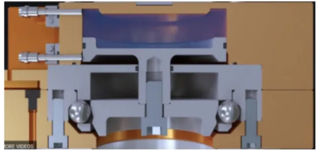
As it was mentioned in the previous section, the tools that are going to be used are coupled with a tool changer, this tool changer is a WWR50 from Zimmer, and it is composed by two different parts, the first one is a female tool changer which holds the tool itself, the second is a male tool changer which is connected with the robot.
The female tool changer is connected with the tool using screws, it is possible to see in figure 7 the main dimensions of this tool. This system has a normalized set of holes which are identified in figure 7 by the number 11, which allows a physical non-permanent connection with the tool.
The male tool changer, is the part connected with the fist of the robot through a normal-ized set of screws identified in figure 7, by the number 1
Figure 7: Main dimensions of the female tool changer [12]
The tool changer uses pneumatic power to make the connection between both its parts. The male tool changer possesses a special set of spheres, that are used to make the connection between both parts of the tool changer.
When the user wants to connect the female part with the male part, it inserts the flange the male within the female, afterward, a double effect pneumatic cylinder pushes the set of metallic spheres inside especially dimensioned slots in both the male and female parts of the tool changer, allowing a strong grip force between both parts of this component [12].
This tool changer is also fail-safe, this means that in the event of lack of power both sides of the tool changer will remain coupled, this is due to the high tightening strength and a very small gap between the metallic spheres. To separate the 2 parts, the pneumatic cylinder must be moved it in the opposite direction breaking the grip between its parts.
It is possible to see the coupling movement in figures 8, 9, 10, and 11. In figure 8 the male and female tool changer are touching each other but are not connected. In figure 9 the male pneumatic cylinder is activated pushing the metallic spheres inside the female tool changer, in figure 10 the tool changer is fully coupled and ready to use. In the last figure, we see the returning movement of the cylinder and the releasing of the connection.
Figure 8: Male and female tool changer before connection
Figure 9: Pneumatic cylinder advancing in to the female tool changer
Figure 11: Returning effect
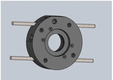
The WWR50 also has set of holes, identified in figure 7 as 34, to insert components that will allow the storage of the combination of the female tool changer and tool, in an appropriate storage station [12].
We can see in figure 12 a 3D representation of the female tool changer with pins attached, this tool changer can then be placed in a holder using these pins.
Figure 12: Solidworks view of the female tool changer, with pins attached
This example was generated using Solidworks, one of the main tools of this project. We can see that the pins that were used were an example, it is possible to connect different devices to make a more suiting fixation system.
3.3
Tool Changer holder Objectives
Before prototyping a solution for the tool changer holder, it is first necessary to analyze the different objectives of this system and how they should be balanced between each other. The most relevant aspect to consider is the stability of the tool in the holder, it is necessary to guarantee that, while in the holder, the tool will not have any kind of movement.
It is also important to take into consideration the type of movements that the robot needs to make to manipulate the tool, as well as, the tolerance of these movements. It is preferable smaller movements and systems with a larger dimension tolerance.
The price of the solution is an important parameter to consider when dimensioning the holder. A simpler holder with less and cheaper parts will be preferable when compared to a more complex one.
Another very important concept to consider when designing the holder, is the of space the tool will require inside the industrial area. The space usage must be minimized as much as possible.
3.4
Tool changer holder Concepts
3.4.1 Vertical holder
It is now possible to create an initial design for the holder. First, it was analyzed the proposed holder by Zimmer, as standard holder for this kind of tool changers. This holder is a vertical one, which means that once the tool is placed in the holder the working end will be vertically located. This can be illustrated in figure 13.
The holder has 2 grooves parallel to each other, identified in figure 13 by the number 1, and requires the usage of 4 pins attached to the female tool changer. At the end of these grooves that are 2 couplings where the pins will be fixed, this is made of flexible metal and have a stabilization function for the female tool changer. In figure 13 this is identified by the number 2.
Figure 13: Standard holder
Although the robot will be placed vertically, the movement to a place of the tool in the frame is horizontal, that is, the movement must be made according to the axis x, and not the axis z.
It is possible to see in figure 14 how the robot should move itself to place the tool. In figure 14 a, the robot is just holding the tool, in figure 14. b the robot has faced the tool downwards and prepares to enter the holder. In figure 14. c, the tool has entered the holder, the movement between figures 14. b and 14. c must be linear as the grooves are also linear. In figure 14. d the tool has been placed and the robot is now free to return to is original position.
(a) Robot first position (b) Robot second position
(c) Robot third position (d) Robot fourth position
Figure 14: Movement made to place the tool
Notice that the values of the displacements of the robot were not mentioned, which is due to the variety of possible tools that can be used in a holder. A large tool may require the robot to be placed fairly far from the holder before it initiates is linear movement, this is, the tool in figure 14. b, so it can safely be placed. A smaller tool may not require such additional effort.
It is also important to refer to the linear movement present using this holder. As was said before, certain performance parameters must be respected to obtain a safe usage of the robot, a large linear movement may create some difficulty, however, and due to the fairly good ability of the robot, it should not be problematic.
The removing of the tool from the holder is in all similar to the movement to place the tool, except is made in the opposite direction, it goes from d to a, being the tool picked in the part of the movement referenced by c.
Vertical holder has some advantageous regarding a horizontal one, as it allows a very stable position for the tool due to the existence of 4 holder points equally divided in space. The programming of the robot also does not raise many concerns, as it doesn’t require any
There are some disadvantages regarding an horizontal holder, they mostly lie within the occupation of factory space. Due to the tool being placed vertically the space beneath them can not be utilized to save more tools, as the larger end of the robot may collide with the standing tools.
Using the vertical arrangement every tool must be stored side by side. The space usage could be improved if there is also an horizontal holder to store tools, allowing both storage side by side, as well as, tool beneath tool.
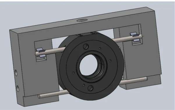
3.4.2 Horizontal solution 1
It was proposed an horizontal solution to allow a more flexible occupation of the space of the multi-tool product line. This solution uses four m4 pins connected with the female tool changer in the holes identified in figure 7 with number 34 to allow the stabilization of the tool. The main frame as a rectangular projection with a slightly smaller gap than the distance between the pins of the female tool changer.
In the main frame there are 4 m6 holes, where screws can be inserted to allow a connection between the holder and an eventual rack, where the solution will be applied.
The tool changer will tightly slide inside this gap. Due to the small difference between the gap in the frame and the gap between the pins the female tool changer will be stuck in the frame and remain incapable of rotating.
In the main frame there are also special couplings at the end of the gap, which are the same used in the vertical holder, and have the function to increase the stability and making difficult an eventual translation of the pins. This structural can be seen in figures 15, 16 and 17
Figure 16: Horizontal Solution without tool 2
Figure 17: Horizontal Solution with tool
Analyzing figure 17, it is possible to see a small circular hole at the top of the frame, in this hole, there will be inserted a proximity sensor which then is connected with the controller giving information about the existence or absence of a tool in this holder.
This solution offers an obvious advantage regarding space occupation, especially when combined with the vertical holder, as the tools can be more tightly packed. It also increases the flexibility of the tools as it will allow to a more broad range of option when deciding where should each of the tools be stored.
There may, however, be some problems regarding the tool stability when considering a very heavy tool due to the possibility of the tool rotating or sliding when stored in the holder.
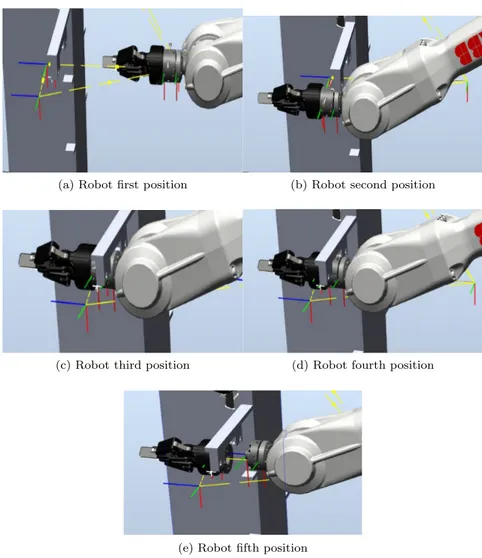
The figure 18 illustrates the movement of the robot to place the tool.
In figure 18. a the robot is just standing in front of the holder, afterward, it dislocates himself to a position slightly more advanced than the location of the holder, this position is illustrated by figure 18. b.
Once the robot reaches this position, it moves upwards to the location where the pins are at exactly the same level as the gap, afterward it moves inside this gap until it reaches the metallic couplings. Once that is done, it releases the tool being free to return to its original position.
(a) Robot first position (b) Robot second position
(c) Robot third position (d) Robot fourth position
(e) Robot fifth position
Figure 18: Sequence of figures of the robot placing the tool
The retrieving of tools is in all similar to this type of movement except for being made in the opposite direction, as it was for the standard holder.
3.4.3 Horizontal holder solution 2
Both solutions use 4 pins. It may be interesting for the development of a solution that doesn’t require such a large number of pins. The interest in using fewer pins is because these tools will be used to manipulate objects in a real workspace, therefore, these pins can bump into objects, making the programming of the movement of the robot more complex.
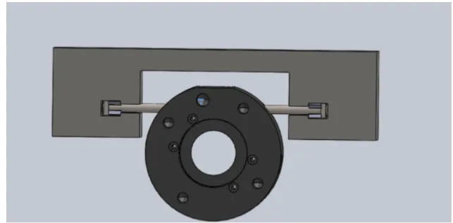
The second proposed solution has the objective of eliminating the necessity of 4 pins, using instead only 2. Instead of using the 4 previously mentioned pins there were only used two, each of them had, in its further end, a square nut attached. The holder had two special dimensioned slots that were slightly smaller than the side of the square nut. There are also the two couplings at the end of the main frame, again, destined to increase the stability of the tool changer once this has been placed there.
To place the tool in the holder, the pins and square nuts slide inside the slots in the holder, all the way until it reaches the couplings. At this position, the square nuts avoid the rotation of the tool due to the tight gap between them and the slots in the holder, the couplings would again help stabilize the tool and prevent any kind of translation of the system.
It is possible to see in figure 19 this holder.
Figure 19: Second horizontal solution with tool
The movement of the robot to pick and place the tool is in all similar to the movement presented in the first solution.
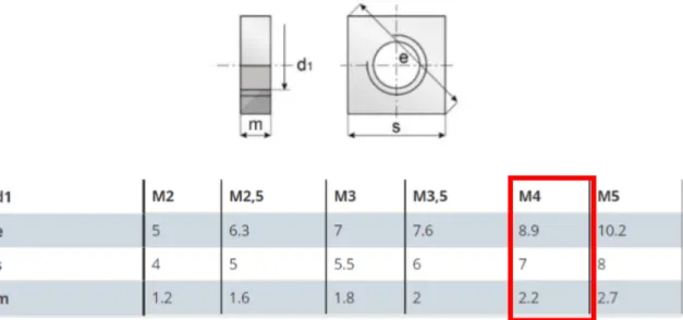
Analyzing table 3, which are the nuts normalized according to DIN 562, it is possible to see the existence of only 4 different types of nuts, the choice of the nut that was going to be used was made considering the diameter of the pin, this is of 4mm, therefor the nut will be use is a m4.
Table 3: Square Nut - DIN 562
The minimum size of the gap, corresponds to the value ”s” in this case 7mm, however and due to the performance parameters, it is necessary to have a larger gap to safely place the tool in position. The minimum value of this difference is of 7.04m, however, it is important to have a safety coefficient when dimensioning these slots.
Considering a safety coefficient of 10, the gap between the nut and the slots is 0.4mm, and the total gap is 7.4mm. The difference between the top of the nut and the top of the slot will allow a small rotation of the nut, and therefore, a small rotation of the tool. With this safety coefficient of 10, there will be a rotation of 3.38o.
If it is only used a safety coefficient 2 the rotation angle would be of 0.66o, this kind of
rotation should be taken into account when choosing and programming this kind of holder for the tool changer, however, it is not a prohibitive factor when choosing this holder.
3.4.4 Horizontal solution 3
The third solution has similarities with the second solution, the holder has a similar shape and the tool changer uses the combination two pins and square nuts, however, this solution takes one step further in the stabilization and centering of the tool changer.
In this case, instead of using normal square nuts, it was employed as a special designed square nut with a cavity within one of its faces, the one contrary to the center of the tool changer. This cavity has a circular shape, and its design to create a self-centered mechanism. To do this there are two pins in the holder, that have a complementary shape of the cavity’s in the nuts and are connected to the main frame of the holder trough springs, these pins are located at the end of the slot.
The movement of placement of the tool in the holder is in all similar to both the horizontal solutions, it also exists the same coupling at the end of the slot where the pins slide in to.
In this solution, however, when the robot reaches the end of the slot where the special pins are located, there is a connection made between the nuts and the pins. Due to the springs having the same strength from each side the tool changer will be centered in the main frame of the holder. This solution can be seen in figure 20 and figure 21
Figure 20: Self centrage view
by more than a few millimeters the tool will return to its place which increases the flexibility and allows this tool changer to be used with a less accurate robot.
The most obvious advantage given by this structure is the self centering mechanism, as it was previously said that the robot has some performance parameters and the position where the tool is left may not always be reached in the same way, therefore having this mechanism will allow the holder to re-position the tool, allowing this to be always in the right location. These solutions are composed of a high number of different components, most of them not normalized, this fact will severely increase the total price of the system, as they will have to be individually made. If we consider this structure made of aluminum the price of machining will make the holder even more expensive.
3.5
Critical Analysis
It is now important to analyze the different constructive solutions and compare them to each other.
The main guidelines to chose the holder are referenced in the section ”tool changer holder objectives”, it will be considered as the main objectives, the stability of the tool in the holder, the type and complexity of the movements of the robot to reach the holder, the price of the holder and amount of space required when the tool is placed in the holder.
3.5.1 Tool Stabilization
In terms of stabilization of the tool, it is fairly simple that the vertical solution will be the best option, as there is no rotation of the tool in the robot, as well as very good weight distribution in the holder. All of the horizontal solutions score similarly in this aspect, even Although the solution number 3 is slightly better due to the additional stability force given by the springs.
3.5.2 Movements difficulties
The second aspect to analyze is the type and complexity of the movements to pick and place the tools in the holder. The horizontal solution applies a shorter movement range that the vertical solution making these types of solutions better in comparison to the vertical one. The solution number 3, allows a better movement tolerance in comparison to the other horizontal solutions, as the tool will always be centered even if the robot fails to place the tool in the exact position.
3.5.3 Construction Process
The third aspect to consider is the price of the different solutions, different aspects affect this price, but the most important variables are the material of the holder, the number of none normalized parts, and the number and complexity of the machining operations that will be necessary to perform.
There are two main possibilities for the materials of the holder, the first and most obvious is making the holder in aluminum, as it is a cheap and resistant material, that can be machined from a block of material. The second option is to make this holder using an additive process, such as 3D printing.
The first option is significantly better in terms of material resistance and speed of pro-ductions, however, the price will be significantly higher. Making the holder in aluminum is, therefore, a good option for a large scale production, the 3D printing is a cheaper process, but the final holder may not be as resistant, however, such affirmation would require a more extensive study and the use of FEM software, the production using 3D printing can also be significantly slower, however, and considering this holders are prototypes, it is recommended
influenced by the amount of none normalized parts required for the holder.
The most expensive solution is, therefore, the horizontal solution number three, to the high number of parts, and the two non-normalized square nuts applied. The two first hor-izontal solutions are expected to be cheaper options, followed by the vertical solutions, all with a somewhat similar price. Using ”3Dhubs” website it was assessed the price of both machinings the holder for the horizontal solutions and 3D printing it, the results can be seen in table 4. Notice that this is the price of machining/3D printing one main holder, the final price will be enlarged by the extra parts and will be reduced if it decided to do a larger series.
Table 4: Main holder prices
Solution 3D Printing price(euros) Machining price(euros) Horizontal Solution One 78,64 138,89
Horizontal Solution Two 48,43 98,66 Horizontal Solution Three 50.88 102,57
3.5.4 Space Occupation
The final aspect to consider is the occupation of the space that the tools will have when placed at the holders. In this aspect, the vertical solution is not the best option due to the high need for space, however when combined with any of the horizontal solutions, the vertical solution works very well.
In this aspect is simple to understand that the best option is a combination of solution and not a single solution.
4
Tool Changer Programming
4.1
Application Objectives
The objective of a tool changer application is that given the location of a tool, the robot should be able to pick and place it at any time automatically. To do this, the user must first teach the robot where the tools are located moving the robot to the tool position and saving this position in the robotic system.
The developed application should be as universal and scalable as possible, in a way that if a completely different disposition of the holders were used, as well as a higher number of tools, the robot could still pick them up, given a previous calibration of the system.
The program should also allow the user to select the tool that he wants to pick or place at any time.
This application can be used in three separate moments:
• A first moment, where the user teaches the location of all the tools that are going to be used in the project to the robot.
• A second moment, where the movements of the robots are defined, tested, and if needs be, adjusted, to assure a safe movement of the robot.
• A third moment, where the user can pick or place the tools that were previously defined according to the needs of his project.
It is also important to remember the different possibilities for the tool changer holder as they have different kinds of movements to pick and place the tool.
The holder that will be initially considered is the vertical one, however, the movements of the robot can be readjusted inside the program to accommodate most of the holders.
4.2
Tools and Software
To develop a tool changer application there is the necessity to consider different software, firstly we need to consider the language of the robot, then the software that was used to build the HMI and finally the program to simulate the system.
The robot used in this project was an ABB, these kind of robots have a physical console that can work as an HMI to help manipulate and program the robot, which can be seen in figure 22. This company also offers an array of programs to help define applications for this robot.
Figure 22: Flex Pendant [5]
The ABB programming language is named RAPID, this was the language used to program the robot, which is quite vast and powerful, therefore there is a necessity of explaining some of the concepts inherent to this program.
ABB provides a program named Robotstudio, this is where most of the robot applications are programmed, it includes a graphical station where is possible to simulate the real move-ments of the robot, it also has a series of add-ins that facilitate the full simulation of a real station.
One of the add-ins inside robotstudio is the screenmaker, this is a graphical interface, that allows the user to develop applications for the flex pendant in a more intuitive environment. The creation of a graphical interface for an ABB robot must be done in both the RAPID language and the screenmaker. These two components must communicate between them to share variables and signals, for example, when the user changes a variable or sends a signal through the screenmaker it changes a value in the rapid program, this means the programs are running separately but communicating with one another.
4.3
Rapid
RAPID is the language used in the programming of the different routines that were used in this work, therefore it is important to understand the basic concepts inherent to this programming language, as well as understand how can robotstudio be used to simplify the programming procedure.
The first concept that will be analyzed is the main control mechanisms, which are the different types of routines. It is important to understand the goal of each routine, how they work, and when should they be used.
A major part of the program will be to pick and place tools, such elements are located at different points in space, therefore it will be examined the movement data essential to the RAPID programs.
Lastly, it will be studied the different coordinate systems that RAPID uses to locate and define the different movements of the robot.
4.3.1 Main Control Mechanisms
Procedures The main function type used in rapid is a procedure, this is a piece of code that runs sequentially, and don’t return any value [17]. These functions are used to define paths, which have significant importance within any rapid program.
Functions A function is a control mechanism that given an input returns a determined value, calculated always in the same fashion [17]. It is mostly used when there is a particular expression that needs to be repeated several times during the application of the program. Traps Trap routines are control mechanisms used to deal with interruptions. They are used as a response to a given input, allowing a program to be immediately interrupted to perform a given task. This kind of routines cannot be directly called[17].
There are 4 different ways to interrupt the rapid program to give way to the trap routine: • Using signals, which can be digital or analogical, output or inputs;
• From an error, this is, a trap will run when a certain error occurs; • An interrupt can be fired every few seconds, cyclically;
• A trap routine can be fired every time a variable changes. 4.3.2 Movement Data
Paths A path is a particular type of procedure that defines the way the robot should move between points. It uses ”move” instructions to define how the robot should go to a given
Figure 23: Path Example
rotate to allow a linear movement of the fist, or a joint kind of movement, where if the path is linear or not is irrelevant (instruction ”moveJ”).
It is necessary to characterize the movement speed, this is defined by a ”v” with a number in front of it, this number determines the speed of the robot.
Another parameter to specify a path is the zone, this corresponds to the location where the robot should stop moving towards the target inside the current move instruction and initiates the movement towards the target inside the next move instruction. It is defined by a z and a number in front of it, or a ”fine” if the user wants the robot to reach the exact destination point.
Finally, it is necessary to characterize the tool that the robot is using and the referential that the coordinates are defined.
In figure 23 it is possible to see the different components of a move instructions. First, it is defined as the type of movement, followed by the location where the robot should move, then the zone, then the tool and the coordinate system.
In a path procedure, some instructions define actions that the robot should make at a given target. It is possible to see in figure 23 an example of this case. After the move instruction to ”target11” there is a function labeled ”PulseDO PickX0”, this instructs the robot to pulse a digital output labeled ”Pick0” once it finishes the move instruction to target 11.
Targets The point to where the robot should move is defined by targets. These are data elements that define a given position and a given orientation that the robot can visit. It is determined about a workobject, and also determines the robot configuration.
The position is the spatial location within a coordinate system that the robot should visit. It is defined by the coordinates x, y, and z.
The orientation is the angles of the tool frame when placed in the defined target, it is expressed in quaternions and corresponds to the angles that the fist should have when placed at the target.
The configuration is a confdata type of vector that defines how the joints of the robot should be placed when reaching is a target:
• the first value of the vector represents the quadrant of the first axis; • the second value of the vector represents the quadrant of the fourth axis; • the third value of the vector represents the quadrant of the sixth axis;
• the fourth value of the vector represents the quadrant of virtual axes, this is used to represent the center of the robot fist regarding the other axis.
The quadrants start getting enumerated from 0, representing the first positive quadrant, then they are enumerated counter-clockwise this means that the second positive quadrant is represented by the number one, and the third is represented by the number two [17].
The negative quadrants start at minus one and are enumerated clockwise diminishing, so minus one is the first negative quadrant, and minus two is the second negative quadrant, and so on.
So, if, for example, we have a configuration (0,1,2,-1), the first axis is located in the first quadrant (0o to -90o angle), the fourth axis is located in the second quadrant(90o to 180o angle) and the sixth axis is located in the first negative axis (0o to -90o angle).
Most targets can’t be reached with every configuration, therefore the user must choose a valid configuration. The targets can be defined using the interface on robotstudio, using this method it is possible to test the different configuration and chose a valid one. Using rapid is not possible to verify the robot configurations automatically.
We can see in figure 24 a defined target, the first part corresponds to the position x, y and z, the second vector corresponds to the orientation expressed in quaternions, the third vector is the target configuration and the last vector defines the external joint axis which is used to define the axis positions of additional axes, positioners, or workpiece manipulators.
Figure 24: RobTarget Example 4.3.3 Coordinate Systems Representation
World Coordinate System The world coordinate system (WCS) is the basic reference of the entire work station (robotic cell). This coordinate system is the highest in the hierarchy and all other coordinate systems are referenced with this one.
Workobjects A workobject is a coordinate system used to describe the position of a work-piece and represents a physical location of an object in a workstation [17].
Figure 25: Workobject coordinate system [17]
This coordinate system is particularly useful due to its flexibility, reconfiguration is made easy by using two frames to define a coordinate system. When recalibration is required, it is only necessary to readjust the user frame and all the targets that are defined to that workobject will be adjusted accordingly. A workobject is also useful when the robot should move according to a specified geometry.
Tool Frame A tool frame is a coordinate system associated with a given tool, it has both an orientation and a location, like a target, and is used to facilitate the programming procedure of any motion where this tool is involved.
This coordinate system is mostly defined in the working end of the tool, for example in a welding torch, the tool frame is defined at the end of the torch. with the orientation of z pointing to the welding location.
4.4
ABB RobotStudio
The ABB robotstudio is a program used to simulate real ABB robotic stations, it has a series of libraries where the user can pick a given robot, program it and simulate a real station.
This program has a graphical interface that simulates a real robot performing different tasks, it is a very appealing system because it allows the user to see different programmed routines working in the station the same it would work in the real robot.
This software also allows for a more direct type of programming, as it has a series of buttons that facilitate the creation of targets, paths, workobjects, tools, etc. It is possible to see in figure 26, a series of buttons that allow the creation of different visual elements.
(a) Open/Close Screens
(b) Signal options
(c) Rapid Data
Figure 26: Different functions of the buttons
Smart components In many different station and simulations, there is the necessity of using smart components, these components are in fact properties associated with a particular tool or object, and are used to simulate a certain function
For example, to simulate the picking and placing of components there can be used attach-ers which connect two objects in the simulation, making them move has one, and dethatchattach-ers that cancel the attacher propriety.
Smart components can also simulate sensors, to detect objects inside the simulation, and can simulate constant movements to simulate for example a conveyor.
Parts Using robotstudio it is possible to import geometries that were built using CAD software. These geometries may have different purposes and they can, for example, simulate a product that the robot should pick, or an obstacle that the robot can not touch.
These parts are also the bases for simulating tools, it is possible to define a given geometry as a tool that the robot can use, it is even possible to define movement inside this tools such
4.5
Screenmaker
The process of creating this flex pendant application using screenmaker is simple to understand. On the main page, there is an interface where the user drags different controls to the work area, which can be seen in figure 27, this is the area that will later be exported to the flex pendant. The user must then define what each of the objects inside the work area will do using a different interface, seen in figure 28.
Figure 27: Empty Work Area
Figure 28: Definition Screen
It is possible to see in figure 29 the most common controls used in the screenmaker applications. These controls can have different functions, and constitute the main tools that the programmer uses to define the HMI.
Figure 29: Most common controls
The most basic object used in the screenmaker is the button. To place a button in the HMI the programmer must drag this component to the work area, it can then define its properties and functions by clicking on the button.
There are different functions that this controller can perform, it can open and close a screen, it can read, write, set, pulse, invert or reset a signal, it can read or write a Rapid data, which, is a variable within the rapid part of the project, or it can read or write a variable within the screenmaker application. This functions can be seen in figure 30.
(a) Open/Close Screens (b) Signal options
(c) Rapid Data (d) application variables
The values in this combo boxes are defined in the properties menu under data, they are bound to an array of options implemented further in the RAPID program. In the previous example, the combo box would be bounded to an array where all the available tools were declared.
The value inside the combo box can also be bonded to a single persistent variable inside the rapid program, this implies that when the user selects a value inside the combo box the persistent variable to which the combo box is bonded will also change accordingly.
The bonding of variables is made using the properties menu that can be seen in figure 31.
Figure 31: Properties menu
An element that can be used to give feedback to the user is the led, this is a visual element that will light up under certain conditions, and can be bonded with both a signal or a variable. For example, a led can be added to inform the user if a certain tool is available or not.
Another useful elements are the labels, this are boxes with a given text, and can be used for giving basic instructions or identifying a certain tool. To define a label the user must drag this command from the control boxes and then write, the information he wants to display there.
There are also text and number boxes, which are elements where the user can freely define numbers and text respectively. These elements are useful for example to define coordinates because this element is not bonded to an array, this means the user can define any value for those coordinates.
4.6
Station
The first thing to do in this system is to create the station that will simulate the station, which is done in Robot studio. This simulation is both graphical due to a visual representation of the workstation and true to reality, as it could be directly applied to a station without the necessity of a great deal of further work.
As it was previously mentioned the robot is an ABB 2600 20kg 1.65m, which is contained in the libraries provided in robotstudio, therefore it is only necessary to select the said library and an appropriate controller to create a base station, which can be seen in figure 32
Figure 32: Empty Station
Once a station has been defined is important to import, create and attach the tool that is going to be used to the robot, in this case, the tool is the male tool changer.
To build this component, it is first necessary to get a 3D representation of the tool, this task is simplified because such a file is made available for download by Zimmer. Once the model has been downloaded it can be directly imported to the station, with an appropriate file type, which is a .SAT file. It is possible to see in figure 33 the male tool changer in the robot studio station.
With the tool imported, it is necessary to define a frame that will later be the tool center point. In the male tool changer, the tool center point corresponds to the center of the flange that goes inside the female tool changer to perform the connection between both parts. The orientation of this tool should be with z parallel to the flange.
Once both the geometry of the tool has been imported and the tool center point has been defined, it is possible to compile the tool.
In the robotstudio it was selected the create tool option, and used the imported geometry has the tool part and the previously created frame as the tool center point. It was also defined as the mass and center of gravity of this tool, for further calibration.
Once both the station and the tool were properly defined, it was necessary to import the rack, holders, and tools that were going to be used. This process is in all similar to the one used to make the geometry for the tool, a 3D model was generated and then imported to the robot studio using an appropriate file type.
The imported tool rack had merely a testing purpose and simulation requirements, it was not a defined part of the project at this point. This rack was designed to be as common and simple as possible, it was meant to simulate a possible tool rack. The geometry used can be seen in figure 34, again it could be used a different geometry.
Figure 34: Station with tools
There was also the need to simulate sensors associated with the rack, in this case, retrore-flective sensors, that would allow the robot to detect the presence of tools in a determined holder. These sensors can be simulated using smart components, it was used one for each of the holders.
Some tools may require an input to work, a gripper needs indication to close or open is fingertips, a welding tool needs information regarding when to weld, the male tool changer will also need to receive a signal to know when it can activate the pneumatic sensor to connect
himself with the female tool changer. Smart components can again be used to simulate these effects.
To define the smart component it is necessary to first create an empty smart component and then define is function. To simulate the picking of tools it was used as an attacher, this component ”glues” 2 parts together, as once active they move as one. The attacher is composed by two parts, the first one is the tool that will pick the object, in this case, the male part of the tool changer, and the second is the component that is going to be picked, which is the tool. To separate the components were dethatchers, which are defined similarly but have the opposite function.
This smart component will only work with the particular combination male tool changer and tool defined, this means it is not possible to have a universal smart component to pick or place any tool. To simulate multiple tools it is necessary to create multiple smart attachers and dethatchers, one for each of the tools.
4.7
Program Structure
The built station has the function to help develop and simulate the application is not associated with the final program. This final program can be divided into three hierarchy stages:
• The first is the calibration stage, at this moments all the paths, targets and workobjects needed to the tool changer program are generated, those are then saved to be used in subsequent stages
• The second stage is a manual testing moment, basically is where all the procedures required for the tool changer are defined and stored. It is also used to test if the tools can be safely picked and placed.
• Finally, the application stage, this moment is not truly imbibed in the created program, it corresponds to the user part of the program, is where he can call the created routines to pick and place the tools, which are stored in the manual testing moment.
The two first stages of the program are constituted by two other parts. A screenmaker application which is an HMI, and it is used to simplify the program use, and a RAPID program which controls the robot.
These two parts are not entirely separate, as they must communicate between them to share variables and orders.
In figure 35, it is possible to see an explanatory diagram of the communications between the entire program.
Calibration Stage
RAPID
Screen Maker
Manual Stage
RAPID
Screen Maker
Aplication Stage
Figure 35: Communications between all the parts of the program
The communication between the RAPID programs in the calibration stage and the manual testing stage and the communication between the RAPID program in the manual stage and the application stage, is very straight forward, as they mostly share variables.
The communication between the screenmaker and the RAPID is a little more complicated, yet is somewhat systematic. In this section, there will be a more synthetic explanation of how some of these communications are made and a mapping of the different shared variables. One of the most used mechanisms in this program is trap routines. They are used because some of the routines present in the program must be done when the user presses a button.
The different ways to interrupt the program have already been analyzed. It makes little sense to interrupt the routines from an error message or in a cyclical fashion.
It would be possible to either interrupt the routines from a signal or from a persistent variable. From the user point of view, it would significantly simpler to use persistent variables instead of signals, because, the former implies the creation of all the signals manually in each of the stations. Using the variable method, the information can be stored in the tool changer application.
![Figure 3: RoboDK Full Animation [6]](https://thumb-eu.123doks.com/thumbv2/123dok_br/15705061.1067955/27.918.270.678.456.694/figure-robodk-full-animation.webp)
![Figure 4: PAL RTC system [10]](https://thumb-eu.123doks.com/thumbv2/123dok_br/15705061.1067955/28.918.207.661.279.595/figure-pal-rtc-system.webp)
![Figure 7: Main dimensions of the female tool changer [12]](https://thumb-eu.123doks.com/thumbv2/123dok_br/15705061.1067955/34.918.74.788.147.791/figure-main-dimensions-female-tool-changer.webp)