Tiago Miguel André Rodrigues
Licenciado em Ciências de Engenharia Mecânica
Wire and arc additive manufacturing: equipment
development and parts characterization
Dissertação para obtenção do Grau de Mestre em Engenharia Mecânica
Orientador: Professora Doutora Rosa Maria Mendes Miranda, Professora
Associada com Agregação, aposentada da Faculdade de Ciências e
Tecnologia da Universidade Nova de Lisboa
Co-orientador: Mestre Valdemar Rebelo Duarte, Faculdade de Ciências e
Tecnologia da Universidade Nova de Lisboa
Wire and arc additive manufacturing: equipment development and parts characterization Copyright © 2018 Tiago Miguel André Rodrigues Faculdade de Ciências e Tecnologia, Universidade Nova de Lisboa A Faculdade de Ciências e Tecnologia e a Universidade Nova de Lisboa têm o direito, perpétuo e sem limites geográficos, de arquivar e publicar esta dissertação através de exemplares impressos reproduzidos em papel ou de forma digital, ou por qualquer outro meio conhecido ou que venha a ser inventado, e de a divulgar através de repositórios científicos e de admitir a sua cópia e distribuição com objetivos educacionais ou de investigação, não comerciais, desde que seja dado crédito ao autor e editor.
Acknowledgments
During my academic path I cross myself with people that made me what I am today I helped me to carry out this work, to them my grateful thanks.
First, I would like to express my sincerely thanks to my supervisor, Professor Rosa Miranda, for accepting me to develop a research in this field and for her constant guidance and support along these seven months.
Second, to my co-supervisor, Valdemar Duarte whom always was available to support and advice with my experimental work.
To Professor Telmo Santos for assistance with development the equipment and for providing the infrared thermography camera.
To Professor Jorge Pamies Teixeira and Professor Carla Machado for inviting me to be a monitor of the laboratories of the Mechanical Technology Group of Mechanical and Industrial Engineering Department at Nova University for three consecutive semesters.
To Professor Rui Silva, from CENIMAT I thank for helping with SEM analysis in such a hurry.
To Eng. Marta Freitas, from ISQ for performing the Charpy impact test so promptly.
My sincere gratitude to Mr. António Guinapo Campos and Mr. Paulo M. G. Magalhães for their everyday assistance and friendship.
To my colleagues, David Negrão, Gonçalo Vieira, Henrique Barata and Rui Santos for their companionship throughout these 5 years. Lastly, to my laboratory partners André Silva, Beatriz Crispim, Miguel Machado and Patrick Inácio, my sincerely thanks.
I must express my very profound gratitude to Iana, for her compassion, partnership, loyalty and strength during all these years, she is responsible for my success and one of the most important persons to me. I hope to return such unfailing support throughout my life.
Lastly but not least, to my parents, Rui and Jacinta, for their constant support, kindness, love and for their efforts with providing the best education possible.
Resumo
Wire and arc additive manufacturing (WAAM) é uma tecnologia que compete com as tecnologias de produção aditiva por laser, sendo as maiores vantagens: baixo custo inicial, baixos custos de funcionamento de manutenção, capaz de produzir peças funcionais sem defeitos internos.
Esta tese teve como objetivo de testar e validar um sistema de posicionamento de 3 eixos, produzido no Núcleo de Tecnologia Industrial do Departamento de Engenharia Mecânica e Industrial da Universidade Nova de Lisboa.
As principais características do equipamento são as seguintes: 4.5 m3 de espaço de trabalho,
velocidade de deslocamento máximo no eixo X e Y de 59 mm/s e de 2 mm/s no eixo Z, caracterizado por um desvio posicional máximo de 0.02 mm e uma amplitude de deslocamentos devido às vibrações do equipamento na ordem dos 0.2 mm durante um movimento unidirecional. O equipamento foi validado produzindo peças em aço de alta resistência com uma fonte de soldadura MIG/MAG, em que foram monitorizados os ciclos térmicos em diferentes camadas através de uma câmera termográfica. As peças fabricadas foram avaliadas pela sua geometria, microestrutura e propriedades mecânicas.
Obtiveram-se peças com bom acabamento superficial tendo sido medida uma ondulação da ordem de grandeza dos 300 μm e sem defeitos internos. Globalmente as peças caracterizaram-se por uma isotropia tanto a nível mecânico como microestrutural. A microestrutura é constituída por ferrite acicular e perlite com durezas inferiores a 320 HV. A espectroscopia por dispersão de energias confirmou que não houve perda dos principais elementos de liga. Os valores da tensão de rotura variaram entre 700 e 809 MPa, dependendo dos processos de processamento. Os ensaios de impacto Charpy em provetes com entalhe em V de dimensões reduzidas registaram valores de energia de absorção de 15 e 18 J nas direções longitudinal (Y) e normal (Z). Observou-se uma superfície de fratura dúctil que também é um indicador relevante do desempenho mecânico das peças produzidas por WAAM.
Palavras-chave
Produção aditiva, WAAM, soldadura, equipamento, aço de alta resistência, microestrutura, propriedades mecânicas
Abstract
Wire and arc additive manufacturing (WAAM) is finding applications in different industrial sectors where it shows to be competitive compared to laser based additive manufacturing technologies. Two major advantages are associated to WAAM: it is a low capital investment technology with reduced running and maintenance costs and allows to manufacture parts with insipient or no porosities.
This study aimed at testing and validating a three-axis positioning system designed and manufactured at Mechanical Technology Group of Mechanical and Industrial Engineering Department at Nova University.
The major characteristics of the developed system are the following: 4.5 m3 working space, a
maximum travel speed of 59 mm/s for the X and Y axes and of 2 mm/s for the Z axis. A maximum positional deviation of 0.02 mm, a minimal travel speed deviation of 0.24 mm/s and a displacement of 0.2 mm of the welding torch due to vibrations during a unidirectional movement. The equipment was validated by manufacturing thin walls by deposition of a high strength low alloy (HSLA) steel wire with Gas Metal Arc Welding (GMAW), monitoring the thermal cycles by infrared thermography to evaluate them in different layers. Geometrical, microstructural and mechanical characterization of parts was performed.
Manufactured parts exhibited good surface finishing measured by the surface waviness that was around 300 μm and no internal defects were observed. Parts were isotropic as far as microstructural features and mechanical performance are concerned. The microstructure was mainly constituted by acicular ferrite and perlite with hardness below 320 HV. Energy dispersive spectrometry was performed, and no element loss was identified. Ultimate tensile strength varied between 700 and 809 MPa, depending on the process parameters. Resistance to impact was assessed by Charpy V impact tests with reduced size specimens and the absorbed energy registered was of 15 and 18 J, in longitudinal (Y) and normal (Z) directions, respectively. A ductile fracture surface was observed which is also a relevant indicator of mechanical performance of parts produced by WAAM in a HSLA steel.
Key-words
Contents
Acknowledgments ... i Resumo ... iii Palavras-chave ... iii Abstract ... v Key-words ... v Contents ... vii List of figures ... ixList of tables ... xiii
Acronyms ... xv 1 Introduction ... 1 1.1 Motivation ... 1 1.2 Objectives ... 2 1.3 Thesis structure... 2 2 Literature Review ... 3 2.1 Additive manufacturing ... 3
2.2 Additive manufacturing technologies for metal parts ... 5
2.2.1 Powder bed fusion ... 6
2.2.2 Laser metal deposition ... 7
2.2.3 Wire and laser additive manufacturing ... 7
2.2.4 Wire and arc additive manufacturing... 8
2.3 Gas metal arc welding ... 10
2.4 Recent WAAM developments ... 12
2.4.1 Process parameters... 13
2.4.2 Welding shielding gas... 14
2.4.3 Residual stress and distortion ... 14
2.4.4 Path planning ... 16
2.4.5 Equipment ... 16
2.4.6 In-situ monitoring ... 17
2.5 Chapter resume and conclusions remarks ... 17
3 Equipment development and characterization ... 19
3.1 Equipment specifications and requirements ... 19
3.2 Equipment components ... 20 3.3 Characterization techniques ... 24 3.3.1 Accuracy tests ... 24 3.3.2 Speed tests ... 27 3.3.3 Vibration tests ... 28 3.4 Chapter resume ... 29
4.3 Vibration tests results ... 39
4.4 Chapter resume ... 40
5 Parts manufactured by WAAM and its characterization ... 41
5.1 Experimental procedure ... 41
5.1.1 Material characterization ... 41
5.1.2 Buildup of samples ... 42
5.1.3 Infrared thermography ... 43
5.1.4 Deposition strategy ... 44
5.1.5 Heat input and deposition rate calculation ... 45
5.2 Characterization techniques ... 45
5.2.1 Visual inspection ... 45
5.2.2 Surface waviness measurement ... 46
5.2.3 Sample preparation ... 46
5.2.4 Metallographic analysis ... 47
5.2.5 Microhardness measurements ... 47
5.2.6 Uniaxial tensile tests ... 47
5.2.7 Charpy impact energy test ... 48
5.2.8 Scanning electron microscopy ... 48
5.3 Chapter resume ... 49
6 Results and discussion of manufactured parts and its characterization... 51
6.1 Macroscopic characterization ... 51
6.2 Thermal analysis... 53
6.3 Microscopic characterization ... 58
6.4 Microhardness test results ... 63
6.5 Uniaxial tensile tests ... 65
6.6 Fractography ... 66
6.7 Charpy impact energy test ... 67
6.8 Energy-dispersive x-ray spectroscopy ... 68
6.9 Chapter resume ... 68
7 Conclusions and suggestions for future work ... 69
List of figures
Figure 2.1 - Metal additive manufacturing processes [10]. ... 5
Figure 2.2 - Illustration of a PBF process [11]. ... 6
Figure 2.3 - Schematic diagram of Laser Metal Deposition [11]. ... 7
Figure 2.4 - Schematic illustration of a WLAM process [16]. ... 7
Figure 2.5 - Schematic illustration of WAAM (adapted from [18]). ... 8
Figure 2.6 - Transfer mode depicted as a function of arc voltage and current intensity (adapted from [45]). ... 11
Figure 2.7 - Representation of layer thickness and hatch spacing (adapted from [54]). ... 13
Figure 2.8 - The deterioration of wall quality by increasing TS and maintaining the WFS/TS ratio at 30 m/min [17]. ... 13
Figure 2.9 - Schematic representation of the shielding device [57]. ... 14
Figure 2.10 - Schematic diagram of the high-pressure roller [60]. ... 15
Figure 2.11 - Steps in the hybrid process of metal additive manufacturing combining WAAM and milling [64]. ... 17
Figure 3.1 - Welding Equipment. ... 23
Figure 3.2 - Representation of test nr. 1. ... 24
Figure 3.3 - Representation of test nr. 2. ... 24
Figure 3.4 - Representation of the test nr. 3. ... 25
Figure 3.5 - Experimental setup of the two-dial indicator and the Z-height gauge. ... 25
Figure 3.6 - Representation of the three different paths performed for test nr. 6: a) square, b) zig zag, c) diagonal with circumference. ... 26
Figure 3.7 - Paths delineated by changing travelling speed during movement for two different paths: a) square, b) diagonal. ... 26
Figure 3.8 - Test nr. 8 setup... 27
Figure 3.9 - Accelerometer setup. ... 28
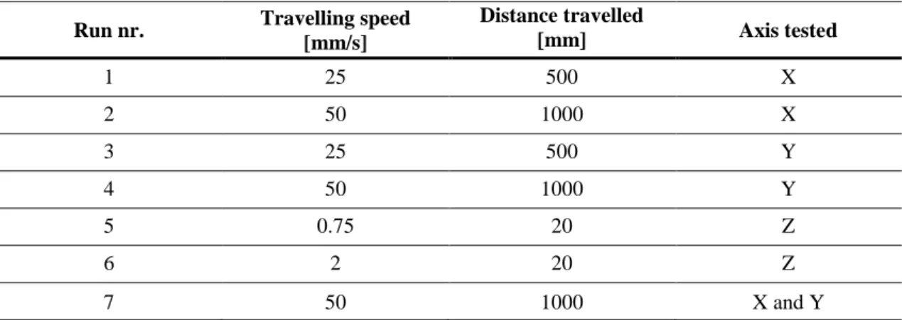
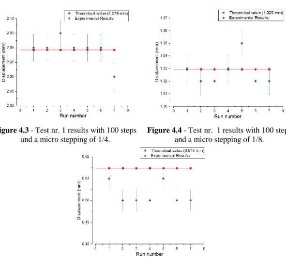
Figure 4.1 - Test nr. 1 results with 100 steps and a micro stepping of 1/1. ... 31
Figure 4.2 - Test nr. 1 results with 100 steps and a micro stepping of 1/2. ... 31
Figure 4.3 - Test nr. 1 results with 100 steps and a micro stepping of 1/4. ... 32
Figure 4.4 - Test nr. 1 results with 100 steps and a micro stepping of 1/8. ... 32
Figure 4.5 - Test nr. 1 results with 100 steps and a micro stepping of 1/16. ... 32
Figure 4.6 - Test nr. 2 results with 100 steps and a micro stepping of 1/1. ... 32
Figure 4.10 - Test nr. 2 results with 1600 steps and a micro stepping of 1/16. ... 33
Figure 4.11 - Representation of the triangle, hexagon and square dimensions measured. ... 37
Figure 4.12 - Displacements recorded in the three axes in time domain of run nr.2. ... 40
Figure 5.1 - LEM LA 200-P current probe... 43
Figure 5.2 - Infrared thermography camera setup on WAAM equipment. ... 43
Figure 5.3 - Wall appearance without travelling speed control [68]. ... 44
Figure 5.4 - Deposition strategy of this work single walls. ... 45
Figure 5.5 - Typical defects that may occur during WAAM depositions: a) Inconsistence wall thickness, b) Variation of final part height and porosity. ... 46
Figure 5.6 - Surface waviness measurement representation... 46
Figure 5.7 - a) Illustration of the removed sections zones b) Cross sections observed macro and microscopically. ... 47
Figure 5.8 - Uniaxial tensile test specimen dimensions. ... 48
Figure 5.9 - Uniaxial tensile tests specimens location. ... 48
Figure 5.10 - Charpy impact energy test specimens location. ... 48
Figure 5.11 - EDS analyzed points. ... 49
Figure 6.1 - Produced parts aspect and corresponding transversal sections of samples: a) P1, b) P2 and c) P3. ... 52
Figure 6.2 - Schematic illustration of the temperature measurement points. ... 54
Figure 6.3 - Sequence of thermal cycles on the 4th tracking point of the P3 deposition. ... 56
Figure 6.4 - Comparison between the HAZ area of samples: a) P2, b) P3. ... 57
Figure 6.5 - Macrostructure along the height of sample P2 (HAZ: heat affected zone, RZ: re-melted zone). ... 60
Figure 6.6 - Cross section micrographs of sample P2 in 12 distinct zones (AF: acicular ferrite). ... 61
Figure 6.7 - Cross section micrographs of sample P3 in 12 distinct zones (AF: acicular ferrite). ... 62
Figure 6.8 - CCT diagram for a HSLA (A: austenite, PF: polygonal ferrite, WF: Widmanstätten ferrite, GF: granular ferrite, AF: acicular ferrite, and M: martensite ) [71]. ... 63
Figure 6.9 - a) Sample P2 cross section, b) Microhardness profiles for sample P2 along the height, c) Microhardness profiles for sample P2 along the width. ... 64
Figure 6.10 - a) Sample P3 cross section, b) Microhardness profiles for sample P3 along the height, c) Microhardness profiles for sample P3 along the width. ... 65
Figure 6.12 - SEM fractographs of a longitudinal P2 tested specimens in: a) center of fracture b) fracture boundary. ... 67
List of tables
Table 2.1 - Costs of different parts per manufacturing process [10]. ... 9
Table 2.2 - Comparison between metal AM technologies... 9
Table 3.1 - Equipment Parameters. ... 20
Table 3.2- Resolution of X and Y axes linear guides. ... 22
Table 3.3 - Resolution of Z-axis linear guide. ... 22
Table 3.4 - Paths delineated on the XY plane. ... 27
Table 3.5 - Paths delineated on the YZ plane. ... 28
Table 3.6 - Welding Torch vibration test... 29
Table 4.1 - Test nr. 3 results. ... 33
Table 4.2 - Measured deviations [mm] after performing a square shape with a = 400 mm. ... 34
Table 4.3 - Measured deviations [mm] after performing a square shape with a = 250 mm. ... 34
Table 4.4 - Measured deviations [mm] after performing a square shape with a = 125 mm. ... 34
Table 4.5 - Measurement deviations [mm] for a zig zag pattern with b = 160 mm and c= 35 mm... 35
Table 4.6 - Measurement deviations [mm] for a zig zag pattern with b = 80 mm and c = 17.5 mm... 35
Table 4.7 - Measurement deviations [mm] for a zig zag pattern with b = 40 mm and c = 8.75 mm... 35
Table 4.8 - Measurement deviations [mm] for the diagonal and circumference geometry with d = 1370 mm and e = 200 mm. ... 36
Table 4.9 - Measurement deviations [mm] for the diagonal and circumference geometry with d = 685 mm and e = 100 mm. ... 36
Table 4.10 - Measurement deviations [mm] for the diagonal and circumference geometry with d = 342.5 mm and e = 50 mm. ... 36
Table 4.11 - Measured deviations [mm] for test nr.7 a) square. ... 36
Table 4.12 - Measured deviations [mm] for test nr.7 b) diagonal. ... 37
Table 4.13 - Measurements registered of the triangular shape. ... 37
Table 4.14 - Measurements registered of the hexagonal shape. ... 37
Table 4.15 - Measurements registered of the squared shape. ... 38
Table 4.16 - Speed test results. ... 39
Table 4.17 - Vibration tests results. ... 39
Table 5.1 - Chemical composition of the ER110S-G wire electrode [wt.%] [66]. ... 41
Table 6.1 - Results of width, height, waviness, deposition rate and heat input for each
deposition. ... 52
Table 6.2 - Comparison between height at arc start and end with the travel speed compensation. ... 53
Table 6.3 - Cooling rate [Cº/s] of sample P2. ... 55
Table 6.4 - Cooling rate [Cº/s] of sample P3. ... 56
Table 6.5 - Residence time [s] between 800ºC and 500ºC. ... 57
Table 6.6 - Growth of interpass temperature [°C] of P2 and P3 depositions. ... 58
Table 6.7 - Ultimate tensile strenght and elongation to fracture of the tested specimens. ... 66
Table 6.8 - Charpy impact test results. ... 67
Acronyms
3D Three dimensional
AM Additive Manufacturing
BTF Buy-To-Fly
CAD Computed Aided Design
CCT Continuous Cooling Transformation
CMT Cold Metal Transfer
CTWD Contact Tip to Work Distance
EBM Electron Beam Melting
FGM Functionally Graded Materials
GFR Gas Flow Rate
GMAW Gas Metal Arc Welding
GTAW Gas Tungsten Arc Welding
HAZ Heat Affected Zone
HI Heat Input
HSLA High Strength Low Alloy
HV Hardness Vickers
I Current Intensity
LENS Laser Engineered Net Shaping
LMD Laser Metal Deposition
MAG Metal Active Gas
MIG Metal Inert Gas
NDE Non-Destructive Evaluation
NDT Non-Destructive Testing
PAW Plasma Arc Welding
PBF Powder Bed Fusion
RMS Root Mean Square
RP Rapid Prototype
RZ Re-melted Zone
SEM Scanning Electron Microscope
SLM Selective Laser Melting
SMA Shape Memory Alloys
TIG Tungsten Arc Welding
TS Travel Speed
WFS Wire Feed Speed
WLAM Wire and Laser Additive Manufacturing
1
Introduction
1.1 Motivation
The 4th industrial revolution, also known as Industry 4.0, is the recent movement towards
intelligent automation technology and is encouraging the integration of innovative production systems and advanced information technologies in industry. In this new era, the utilization of modern manufacturing technologies and processes, such as Additive Manufacturing (AM), is crucial due to the need to meet new demands, namely: personalized products, complex parts with tailored mechanical properties and short delivering times [1]. AM experienced a considerable growth over the last years and reports have shown the potential of this technology [2], although there are still some concerns about its performance (technical and economical) and reliability.
Metals are, eventually, one of the most common materials in engineering due to their mechanical characteristics, therefore AM technologies are aiming at being an alternative solution to manufacture metallic parts.
Amongst the technologies used for AM of metallic alloys, those based on laser are the most common, such as selective laser melting and laser metal deposition, but others have been investigated based on electric arc, such as Wire and Arc Additive Manufacturing (WAAM), that
shown to be competitive with laser. WAAM requires simple low capital investment costs unlike laser, has high deposition rates and can overcome some of the difficulties associated with processing particular alloys such as those based in Nickel and Titanium and Shape Memory Alloys (SMA) [3], or even high alloy steels prone to cracking phenomena. However, a deeper knowledge of the process is needed in order to enhance surface quality, improve strength and fatigue lifetimes. Additionally, non-destructive testing, standardization and certification of AM parts have to be developed since they are still hindering a wider use of these technologies [4].
1.2 Objectives
This thesis has two major objectives:
1- To characterize a developed three-axis positioning system to produce large and complex-shaped parts by AM with metal inert gas/active gas (MIG/MAG) or tungsten arc welding (TIG). This equipment was developed in the framework of an ongoing PhD thesis, so this work aimed to evaluate the main equipment features, in terms of positioning accuracy, vibration levels, and travel speed ranges. This is important to conclude a relevant piece of equipment with industrial characteristics developed in-house at the Mechanical Technology group.
2- To assess equipment feasibility, by producing thin walls and characterize these in terms of geometrical, microstructural and mechanical aspects. Another purpose is to monitor the temperature cycles experienced by the material during part manufacturing with a thermal data acquisition equipment, in order to correlate the thermal cycles with the microstructure and mechanical proprieties.
1.3 Thesis structure
This thesis is structured in seven chapters.
Chapter 2 provides an overview of the AM state of the art, focusing on wire and arc additive manufacturing process. It highlights relevant findings and breakthroughs reported recently.
Chapter 3 gives a brief description of the equipment developed and its features. Chapter 4 presents the experimental techniques used to characterize the equipment.
Chapter 5 describes the experimental procedure to manufacture the parts and the techniques adopted for their characterization.
Chapter 6 presents and discusses the results achieved in this study and finally in Chapter 7 the main findings are summarized and specific topics to continue this research are outlined.
2
Literature Review
According to ASTM Standard F2729-12 additive manufacturing is defined as “a process of joining materials to make objects from 3D model data, usually layer upon layer, as opposed to subtractive manufacturing methodologies”. Other synonyms widely used for AM in the literature are rapid manufacturing, additive fabrication, layer manufacturing, direct digital manufacturing, free-form fabrication, amongst others [5].
2.1 Additive manufacturing
During the last few decades, AM has gained interest for design and manufacturing part models and prototypes based on the rapid prototype (RP) concept. Rapid prototyping is often referred as AM, however, some authors [6] remark that the use of this term no longer describes it, since its potentials are being adapted to fabricate functional components in the aerospace, automotive, defense and medical industries [7]. To standardize terminology, ASTM has created various categories where the current AM machine technologies and future ones can be fitted. The seven categories of AM process definition proposed by ASTM are the following:
• Direct Energy Deposition - material is deposited and melted via thermal energy onto a specified surface, where it solidifies;
• Material Extrusion - the material is drawn through a nozzle, where it is heated and is then deposited layer by layer;
• Material Jetting - a printhead dispenses droplets of a photosensitive material that solidifies under ultraviolet (UV) light;
• Powder Bed Fusion - each powder bed layer is selectively fused by using an energy source like laser or electron beam;
• Sheet Lamination - sheets or ribbons of metal, are bound together using ultrasonic welding;
• Photopolymerization - an ultraviolet (UV) light is used to cure or harden a liquid photopolymer resin, whilst a platform moves the object being made downwards after each new layer is cured.
These groups of processes are capable to produce components with complex shapes that are difficult or impossible to fabricate by the conventional methods such as forging, machining and die casting. These traditional solutions are often impracticable due to the inflexibility of modern designs and the cost associated to produce a die and material wastes. The impact on the development of this manufacturing technology is opening new windows of opportunity for the manufacturing of modern designs and novel materials.
Currently, to answer the demands of the Aerospace industry the focus of AM has shifted to complex-shaped components of Titanium and Nickel alloys. These are used extensively due to high specific strength, thermal and electrochemical compatibility with advanced composite materials [7]. AM has also become a vital element in the concept of the industry 4.0, fundamentally, the idea with this innovative approach is based on the concept of Internet of Things (IoT), it is described as a conception of gathering all the information about production lines, resellers, buyers, products, stock, machines availability and other factors in a big data cloud. Smart factories with IoT implemented will focus on customized demands and AM is the most suitable manufacturing process to promptly obtain parts in a vast range of materials [9]. The overall key benefits and limitations of AM are:
Benefits:
✓ Manufacturing of complex parts without the need for molds; ✓ Some processes do not require post-process machining;
Chapter 2 – Literature Review
✓ Easy to perform slightly changes in the product design without the need to rearrange the production line or build additional dies;
✓ Production of functionally integrated designs in one-step, eliminating the assembly of distinct parts;
✓ Less material waste and fewer raw materials required; ✓ Small production batches are feasible and economical;
✓ Potential for simpler supply chains, shorter lead times and lower inventories. Limitations:
- Parts size are limited by machines build space;
- Some of AM processes are characterized by low build rates;
- Depending on the process, post surface finishing is sometimes required; - Missing quality standards;
- Powder based machines are very expensive;
- Intellectual property rights & warranty related limitations.
2.2 Additive manufacturing technologies for metal parts
AM processes for metal components initiate with a feedstock material such as powder or wire and subsequently solidified with the aid of an energy source such as laser, electron beam or electric arc. Figure 2.1 depicts the most widely used AM technologies to produce metallic components.
2.2.1 Powder bed fusion
In general, powder bed fusion (PBF) techniques use a high-density energy beam to melt a thin layer of powder bed. From the 3D CAD, slices of the model are created, and these slices correspond to layers to be melted after the powder is spread by a roller. After finishing one layer, the build platform is lowered by one layer thickness and a new powder bed is spread. This process is repeated until the part is completed. PBF includes all processes where direct energy is used to melt or sinter a layer of a powder bed and it can be done by electron beam or laser. A standard setup of a PBF machine is illustrated in Figure 2.2. [11]
Figure 2.2 - Illustration of a PBF process [11].
Electron Beam Melting (EBM) uses a high-energy electron beam to heat and melt the metal powder by means of the kinetic energy of the electrons which is transferred to the powder particles. To avoid electromagnetic problems, EBM can only process electrically conductive powders and takes place in a vacuum chamber, so that electrons do not interact with the atmosphere and are not reflected.
Selective Laser Melting (SLM) is very similar to EBM but uses a high-power laser that is a coherent light beam where the energy of the photons is absorbed by the powder particles, increasing its temperature above melting temperature. This process takes place in an inert atmosphere to protect the molten metal from oxidation. SLM typically has a system of lenses and a scanning mirror or galvanometer to move the beam.
Powder laser-based technology has been the most popular of AM processes due to its exceptional precision and narrow material waste since the not melted powder can be reused. However, it has some drawbacks related [12] to energy efficiency (in SLM just 10-20% of the total energy input is used to melt the powder). Other common drawbacks [13], includes low deposition rates, high capital cost, availability of consumables, low quality of the metal powder feedstock, a subsequent machining step is often needed, concerns about health and safety risks regarding the powders and it is limited to build low volume parts.
Chapter 2 – Literature Review
2.2.2 Laser metal deposition
Laser metal deposition (LMD), or laser cladding, is also known as laser engineered net shaping (LENS) [14]. In LMD the powder material is locally supplied by a powder feeding nozzle melts and solidifies in a moving melt pool. LMD is characterized by high efficiency and the flexibility to control the beam position makes it attractive for repairing metallic components. The setup preparation is substantially reduced when compared to SLM. A schematic illustration of the process is presented in Figure 2.3.[11]
Figure 2.3 - Schematic diagram of Laser Metal Deposition [11].
As an alternative, to high power beams, electric arc is a cheap heat source that can be mastered for producing complex metal parts.
2.2.3 Wire and laser additive manufacturing
Wire and Laser Additive Manufacturing (WLAM) is an AM process that uses wire as feedstock and a laser beam as heat source (Figure 2.4). The equipment consists of an automatic wire-feed system that travels along with the laser and this relative motion is usually performed by a robot, resulting in parts with good surface finishing and with homogeneous properties. WLAM is able to fabricate parts in Titanium and Nickel alloys with good performance. High power fiber lasers have been used for rapid prototyping with direct laser melting of wire [15]. However, this process is difficult to automate, to obtain consistent results and has poor energy efficiency due to the large amount of laser energy that is lost.
2.2.4 Wire and arc additive manufacturing
Wire and Arc Additive Manufacturing (WAAM) is inserted in the category of Direct Energy Deposition according to ASTM. WAAM (Figure 2.5) is described as the combination of an electric arc as heat source and wire as feedstock to produce large and complex parts [17]. It uses the fundamental concepts of automatized or robotized processes and welding processes, for instance, MIG/MAG, Gas Tungsten Arc Welding (GTAW) or Plasma Arc Welding (PAW).[18]
Figure 2.5 - Schematic illustration of WAAM (adapted from [18]).
WAAM relies on welding technologies that are largely mastered which is already an enormous advantage. In fact, WAAM may be capable to overcome other technologies limitations including low costs, because it only requires an axis-robot, a power source, a welding torch, a shielding gas and a substrate. It has high depositions rates in contrast with PBF processes, adequate to fabricate large parts. More, close to zero material waste is obtained if the final part does not need subsequent machining, and it is capable to freeform a large variety of materials.
Thus, the desire to mature this process for its adoption into mass production of aerospace components comes from the ability of producing large parts with a low Buy-To-Fly (BTF) ratio, which is the ratio between the weight of the raw material purchased and the weight of the final part. S.Williams et al. [10] studied the economic benefits of WAAM with subsequent machining and compared to conventional machining from a solid block. The developed model considers the prices of tools, materials, substrate, machine, software, electricity and every consumable for each manufacturing process. Several components were analyzed such as: a wing spar, an external landing gear assembly in titanium and a pylon mount. In all studied cases WAAM represented costs savings compared to conventional machining as shown in Table 2.1.
Chapter 2 – Literature Review
Table 2.1 - Costs of different parts per manufacturing process [10].
Designation Process BTF Cost (€ × 𝟏𝟎𝟎𝟎) Cost Reduction
Wing spar Traditional 6.5 8.11 n.a.
WAAM 2.15 5.75 29 %
External landing gear
Traditional 12 18.14 n.a.
WAAM 2.3 5.6 69 %
Pylon mount Traditional 5.1 2.8 n.a.
WAAM 1.5 2.68 7 %
Every process has its capabilities and its field of application so the selection of AM process must be done according to the envisaged application and the avaible equipment.
Table 2.2 presents a summary of studies performed by different research groups and compares different AM processes in terms of surface roughness, layer thickness, deposition rate, dimensional accuracy and materials processed.
Table 2.2 - Comparison between metal AM technologies.
Process Characteristics Surface Roughness Ra [μm] Layer Thickness [μm] Deposition Rate [𝐜𝐦𝟑/𝐡] Dimensional Accuracy [mm] Materials Refs. SLM 5-15 20-100 up to 171 0.04-0.2 AISI 420 stainless steel, AISI 4140, AlSi10Mg, Ti-6A-l4V, SS316L, 17-4PH, 15-PH, TA2, TA15, [19–23] EBM 10-40 50-200 up to 80 0.04-0.2 Ti-6Al-4V, Inconel 718, SS 316, F75 Cobalt Chromium, [20,24–28] LMD 30-60 4-10 up to 300 0.5-1.0 H13 steel, Ti-6Al-4V, IN718, NiTi, Inconel 625 [29–36]
WLAM 8-15 N.A. up to 250 1.0-1.5 Ti-6Al-4V, Fe-based
and Al-based alloys [15,16,37,38]
WAAM >200 ∼900 up to 330 >0.5
Ti-6Al-4V, SS 316, IN 718, H 13 Steel, Fe-based and Al-based alloys, Copper,
Nickel aluminum bronze (NAB) alloy,
5A06 aluminium, 5CrNiMo, HSLA
steel
2.3 Gas metal arc welding
Gas Metal Arc Welding (GMAW) also known as Metal Inert Gas (MIG)/Metal Active Gas (MAG), is a gas shielded arc welding process in which an electric arc forms between a consumable electrode wire and the metal workpiece, while the protection of the weld pool is assured by an active or inert gas. GMAW has been a suitable candidate welding process to be adapted for WAAM due to the following key characteristics [44]:
• Easy to use with almost any metallic alloy; • No welding length restriction;
• High deposition rates and welding speeds; • Minimal post welding cleaning;
• Easily automated.
In the overall, these characteristics well suit MIG/MAG for a high production additive manufacturing application.
However, GMAW is a rather complex process since several phenomena occur simultaneously and several process parameters must be controlled to avoid slight changes that could drastically influence the quality of the final parts. Process parameters include: wire diameter, wire material, substrate material, preheating substrate, welding equipment, Welding Shielding Gas (WSG), Gas Flow Rate (GFR), voltage (V), current intensity (I), Contact Tip to Work Distance (CTWD), Wire Feed Speed (WFS), Travel Speed (TS) and torch inclination.
There are four major modes of metal transfer in GMAW, though the International Welding Institute has a larger classification. These are: globular, short-circuiting, spray and pulsed-spray, and each one has distinct features (Figure 2.6). The selection of the parameters that directly affect the transfer mode is very important since it affects bead width, penetration, bead size, deposition rate, waviness, heat affected zone (HAZ) and the overall performance of the process. The type of transfer mode is mostly determined by the following main parameters: [45]
• Type of current;
• Electrode diameter and composition; • Specific power supply characteristics; • Contact tip to work distance;
Chapter 2 – Literature Review
Figure 2.6 - Transfer mode depicted as a function of arc voltage and current intensity (adapted from [45]).
Short circuit transfer occurs for low current intensities and arc voltages decreasing temperature input, minimizing distortion and residual stresses of the final part. Controlled spray transfer is the most used mode in GMAW applications, it avoids the common spray transfer mode problems, such as high heat inputs due to high voltage and current, random droplet size, intensive fumes and spatters. The use of a power source capable to control release of one drop for every sequence of short-circuiting makes this mode very effective.
The welding shielding gas is one of the most influent parameters, since it affects the weld bead geometry, process stability, transfer mode and weld aspect [46]. Shielding gas used are mostly based on Argon and Helium, these inert gases prevent the molten pool from chemically react with the atmosphere and are responsible for conducting electrons between the wire and the substrate. A conductive gas must be ionized and depending on the gas used the ionization energy differs. Ionization potential is defined as the energy necessary to remove an electron from a gas atom generating an ion, or an electrically charged gas atom by removing the valence electrons and is expressed in electron Volt (eV). Argon has an ionization energy of 15.7 eV, while Helium has an energy of 24.5 eV. Due to his low ionization energy, Argon facilitates arc start and provides a more stable arc. The thermal conductivity is a key parameter when selecting a shielding gas, Helium has a high thermal conductivity resulting in more energy being conducted to the workpiece, leading to wider arcs and increased penetration depth. However, adding Helium to an Argon mixture increases thermal conductivity and ionization voltage, which contributes for a more controlled and constant droplet release and deeper beads.
Active gases such as carbon dioxide and oxygen are commonly mixed with inert gases in MAG. Carbon dioxide is a reactive gas common in MAG that allows spray transfer modes and arc stiffness. It allows high travel speeds and deep penetration in ferrous alloys due to exothermic reaction with iron. However, some alloys may form oxides which modify the melting temperature and result in brittle microstructures [47]. The most common gas shield is Argon with 5 or 20% of
carbon dioxide, which performs high quality beads, with good arc stability easily ignited. Additions of H2 are also used , constraining the arc and improving penetration [48]. Mixtures of
Argon and Oxygen reduce surface tension, facilitating gases ionization, but they tend to originate porosities.
In the pursuit for a better GMAW based system, a variant of MAG has been adapted in additive manufacturing named Cold Metal Transfer (CMT). It is an advanced transfer process in which an incorporated process-control detects when the electrode wire tip contacts with the molten pool and by activation of a servomotor the wire retracts promoting droplet transfer. Current intensity drops to near-zero and thereby spatter generation is avoided. CMT provides a more stable arc and reduced thermal input due to a slight short-circuit period [49]. This process is suitable for an WAAM application due to effective production costs of high value components for aerospace industry applications, such as Ti-6Al-4V and Inconel 625, consequential of the difficult application of subtractive methods onto these materials.
2.4 Recent WAAM developments
Welding processes can be successfully used in AM, but there is limited research on some of its challenges that are yet to be solved. In particular residual stresses and consequent distortions from excessive heat input, optimization of process parameters and deposition strategy, poor quality of WAAM parts, standardization and difficulties associated with removing finals parts from the substrate.
Wire-feed AM techniques are not recent, their roots go back to 1925, when Ralph Baker patented an invention [50] related the use of an electric arc in producing receptacles or containers of ornamental and useful shapes. By that time, he described temperature distribution and heat transfer problems of this process. Noble [51], in a patent filed in 1919 and assigned to General
Electric Co., did the first analysis of cost-effective wire feed arc welding mechanism, describing
the process to repair metal shafts. The author pointed out the need for monitoring and the difficult to control process variables to automate the process. Other exciting developments occurred at the beginning of the 70’s at Thyssen-Hütte AG by using arc welding to produce large shafts and rotors, turbines and electric generators. The author highlights the desire for implementing an automatic online thermal-mechanism to avoid residual stresses and distortion [52]. This “new” fabrication method received considerable interest in the beginning of the 1990’s. The disruptive effects of the “new” fabrication approach interested Rolls-Royce, that investigated along with Cranfield University its performance to reduce the costs of aero engine components. However, the research failed to consider more parameters such as contact tip to work distance, wire feed speed, wire diameter and fusion characteristics [53].
Chapter 2 – Literature Review
Difficulties associated with precision, process control and databases for controlling deposition geometry to increase levels of automation, hindered integration of WAAM in industry.
2.4.1 Process parameters
Besides the key process parameters considered in GMAW welding process, for an AM process there are more process parameters that need to be consider, such as, hatch spacing (hs)
and layer thickness (t), both illustrated in Figure 2.7.[54]
Figure 2.7 - Representation of layer thickness and hatch spacing (adapted from [54]).
Kazanas et al. [17] investigated the production of geometrical features using CMT in which, the low heat input of the process allowed for horizontal walls to be generate from a vertical substrate. A set of experiments varying both the travel and wire feed speeds, maintaining the ratio of WFS/TS, allowed to conclude that TS and WFS are critical regarding wall quality for horizontal walls as illustrated in Figure 2.8.
Figure 2.8 - The deterioration of wall quality by increasing TS and maintaining the WFS/TS ratio at 30 m/min [17].
Duarte [41] studied the influence of the five most relevant process parameters (WSG, GFR, WFS, TS and voltage), for both synergic and continuous welding mode, evaluating the width, waviness and deposition rate of the depositions created. The experimental work allowed to conclude that for both synergic pulsed and continuous mode TS and WFS are the most influent parameters on final width. Concerning deposition rate, WFS is the most preponderant parameter
for both welding modes. TS is the parameter that most influence the surface waviness in synergic pulsed mode whereas for the continuous mode, the TS and WSG are the most significant ones.
2.4.2 Welding shielding gas
The welding shielding gas is one of the most influent parameters, since it affects bead geometry, process stability, transfer mode and weld appearance [42]. Besides its right selection, other methods have been used to improve WAAM parts quality. Xu et al. [56] studied the effect of oxides on the mechanical proprieties by varying shielding conditions. Results were obtained by making one deposition in open atmosphere with pure argon and the other one in an argon filled tent (chamber), in which the oxygen level was controlled below 300 ppm. Extra tent shielding substantially improved the surface waviness and deposition efficiency by 37% and 9%, respectively.
Gas shielding flow was found to be of remarkably importance regarding walls appearance. In this preliminary study [57] it was analyzed gas shielding flow in WAAM, since turbulence flow causes the shielding gases to mixture with the surrounding air resulting in poor shielding conditions and increased atmosphere contamination that can lead to oxidation. A new device (Figure 2.9) consisted in three distinct parts was created. The first part was a diffusion chamber that uniformly distribute the inlet gas, the second was a honeycomb walls that straightens the flow and reduce its lateral velocities, for last, at the end of the chamber, a layer of metal mesh was used to further improve the uniformity of the flow.
Figure 2.9 - Schematic representation of the shielding device [57]. 2.4.3 Residual stress and distortion
Chapter 2 – Literature Review
of material [58]. Residual stresses reduce mechanical proprieties of the component and distortion leads to difficulties in achieving the required tolerances. During WAAM process, high temperatures are achieved and will lead to high deformations that after cooling can lead to residual stresses that if these exceed the local yield stress of the material, will lead to plastic deformation, but if it exceeds the ultimate tensile strength will result in fractures.
The material during a deposition undergoes various cycles of expansion and contraction due to the repetitive heating and cooling .There are many techniques that have been study to minimize the effects of residual stresses and distortions in AM. Mughal et al. [59] investigated the effects of process parameters on the residual stress distribution in a GMAW deposition, pointing out the effect that adopting different deposition sequences has on residual stresses distribution, stating that layers starting from outside to the center was the strategy with the lowest impact on the final parts.
The most innovative method yet was made by P. A. Colegrove et al. [60] , in which, an high-pressure rolling was applied in GTAW process to minimize residual stresses. The roller travels horizontally, parallel to the surface, inducing plastic deformation, due to the compression enforced perpendicularly to the substrate (Figure 2.10). The results were very promising, in terms of microstructure, since grain refinement was possible. Furthermore, rolling the sample after every fourth layer had the same effect on the distortion as rolling after each layer but its appliance can be counterproductive, reducing the deposition rate ratio that is one of the major benefits of this process.
Figure 2.10 - Schematic diagram of the high-pressure roller [60].
Lastly, a suitable solution was validated by means of finite element analysis [61] that considers preheating the substrate. The experimental validation of the walls thermal behavior allowed to conclude that the heat accumulation with preheating results in losses in conductivity,
so when layers are deposited, heat losses are minimized resulting in less sharp temperature gradients and, thus, residual stress and distortion can be avoided.
2.4.4 Path planning
Deposition path planning is extremely important not only because it affects residual stress but also the mechanical proprieties of the final part. Poor planning can result in porosity and lack of fusion between adjoining weld beads. D. Ding et al. [62] created an overlapping model to determine the distance between adjacent beads that could suppress the valleys between them. This parameter plays a key role in achieving the required tolerances, geometry accuracy, as well as good surface finish. By approximating beads, the area of the valley automatically decreases, and it is possible to reach an optimized flat surface when the overlapping area equals the valley area. The models of the bead cross-section profile were developed by means of parabola, arc, and cosine functions. This study identified an optimal distance value between adjacent beads of 0.738 times the width of one bead.
It becomes necessary the development of a software able to carry every phenomenon that occurs during deposition to accurately provide the welding torch path, in order to be obtained fully dense and functional parts. Based on the fact that most software for metal deposition are limited and without public access, Yunyong et al. [63] took advantage of the free open source
CuraEngine introducing new settings to generate G-code to print metallic parts. These settings
permit the torch to toggle on and off, path optimization to avoid crossovers in the same layers, the number of start/stop was minimized and an option to pause the torch was also added for subtract cooling between layers. To optimize the wire feed speed, the expected and actual volume of material were calculated, so that they can be matched. The user sets hatch spacing, thickness, wire diameter and the 3D model and MostMetalCura would recommend the voltage and wire speed for the process besides generating the G-code to be inserted in a CNC machine.
2.4.5 Equipment
Recently, some machine manufacturers are building optimized machines for the arc welding technology, by integrating additive and subtractive manufacturing technologies into one machine can result in shorter delivery times and personalized complex parts, suppressing WAAM major drawback, which is poor surface finish. Figure 2.11 schematically illustrates the procedure of this hybrid solution.
Chapter 2 – Literature Review
Figure 2.11 - Steps in the hybrid process of metal additive manufacturing combining WAAM and milling [64].
Mazak corporation (Japan) unveiled a machine model VARIAXIS j-600AM featuring a
standard WAAM head mounted on the machine headstock as well as an advanced 5-axis multi-surface subtractive capability to produce high-precision parts complete in single setups. Another advancement was made by Mutoh Industries that revealed the model Arc MA500-S1 which uses arc welding technologies. However, these machine, are not versatile, since no additional instrumentation or variation of the welding process is possible.
2.4.6 In-situ monitoring
One of the main obstacles of AM is the absence of control and monitoring during the process. Implementation of an in-process monitoring system during the building of a part, will certainly be a step forward in improving the consistency and uniformity across machines, and will allow qualification of AM parts. In the in-situ sensing area, non-destructive evaluation (NDE) sensors can be used to measure and monitor the temperature, the size of the melt pool and the size of beads, and if successfully integrated with a closed loop control system, they might also be able to detect the presence of defects and measure the part dimensions while it is still being produced.
A recent study introduced an innovative closed loop control system integrated in a WAAM equipment [65]. The existence of a dynamic model where the travel speed is selected as the input control variable and the layer width is chosen as the output increased process stability. To support the algorithm, variable like arc current and voltage, heat dissipation, and interpass temperature were evaluated.
2.5 Chapter resume and conclusions remarks
AM processes are now increasingly being used in many applications due to their unique properties. However, improvements are required to fully implement AM in industry. The growing volume of sales of commercial AM equipment and market predictions point towards a deeper
equipment such as PBF ones, the development of a WAAM technology in a fully optimized equipment becomes essential. Although several progressions have been made to overcome WAAM adversities, such as residual stresses, distortions, consistency of mechanical proprieties along a part and defects are still of great concern for companies.
This work aims to contribute for the development of a three-axis positioning system for WAAM at DEMI-FCT NOVA that will further consider the integration of in-process monitoring for defect detection.
At this stage it envisages to validate the equipment developed by processing a High Strength Low Alloy (HSLA) steel and analyzing the parts thermal cycles in order to correlate with the microstructure and mechanical properties obtained.
3
Equipment development and characterization
The first part of this work consisted on final developments, tests and set to work of an equipment to produce large parts by WAAM. The equipment progressed in four stages: a) assembly the mechanical frame, b) design and connect the electric system, c) install the control system and d) testing and validation assessing its effectiveness and repeatability.
3.1 Equipment specifications and requirements
The conception of the following equipment was based on the following functional requirements:
• Human size scale equipment with capability for additional instrumentation to be coupled on the working platform;
• The moving head should be easily adapted for different welding torch types and for other modules to be attached, such as, non-destructive testing (NDT) equipment; • Independence of the welding torch power and positioning system power supply; • Welding torch capable to control the WFS separately from the welding machine,
The technical parameters of the machine are given in Table 3.1. Table 3.1 - Equipment Parameters.
Power 300 W
Overall dimensions [mm]
Length (X-axis) 2760
Width (Y-axis) 1958
Height (Z-axis) 2000
Working platform size [mm]
X-axis 2400
Y-axis 1500
Z-axis 1250
Maximum feed rate [mm/s]
X-axis 59 Y-axis 59 Z-axis 2 Extruders 400 Maximum Acceleration [mm/𝐬𝟐] X-axis 2000 Y-axis 2000 Z-axis 50 Extruders 1000
3.2 Equipment components
Frame: The structure stability was ensured by using 80x80 mm Bosch Rexroth’s profile that has a high moment of inertia reducing overall deformations without compromise structural integrity. A solid frame that maintains the vibration to an acceptable maximum was essential, since stiffness and versatility are the main characteristics of these profiles, allowing for other machine components to be easily assembled without compromising the strength of the overall structure.
Motion System: The structure comprises a fixed substrate and a travelling head which can move in three orthogonal directions (X, Y, Z) controlled by the seven linear motion guides.
To control the X and Y axis position a drylin ® ZLW-1040 Standart-02 model was selected, which is characterized by a transmission ratio of 70 mm/rev. This model is driven by a belt which guarantees a maximum deviation of ± 0.2 mm from prescribed position.
Chapter 3 - Equipment development and characterization
For the Z axis, since it has to support the weight of moving parts (welding head, wire feeding system, etc.), four drylin® SLW-1040 linear guides were preferred, which use a leadscrew to translate the motor rotation into linear motion with a lead of 2 mm. Each linear guide can tolerate an axial load of 700 N.
Stepper motors and drivers: Each linear guide is actuated through stepper motors, the selected model was the 57STH56 NEMA-23 Bipolar that has an integrated planetary gearbox with a reduction ratio of 4.25/1. These motors were limited to a maximum speed of 375 rev/min, defined by 200 increments per revolution and have a precision of ± 5 %. The assembly was made through shaft couplings to transmit the binary. The motors were controlled by PiBot Stepper
Motor Driver Rev2.2chips by balancing the power fed into each coil and the driver is also able to
sub-divide steps into further increments up to 16 times.
Control Board: This is the most important piece of equipment. The AM machine used an
Arduino Mega 2560 connected to Ramps 1.4 shield. This module is widely used in 3D printers
and it can control the stepper motors up to a 1/16 stepping precision. It is also responsible for the communication with end stoppers, fans, heated bed, with a relay that activates the MIG/MAG welding machine and with the stepper motor attached to the moving head responsible for feeding the wire.
Signal Multiplier: To control the X and Z axis properly the same signal transferred to the X and Z axis in the ramps must be multiplied to every motor of the X-axis and Z-axis move the same distance.
It was essential to calculate this resolution, in order to set in the configurations of the software that will control the machine, to know how many steps the machine should give according to the output required by the G-codes. Equation 3.1 and 3.2 considers the stepper motor steps per revolution, the planetary reduction of the stepper motors gearbox, the mm per revolution transmission of the X and Y linear guides or the screw lead for the Z ones. Additionally, it is necessary to consider the micro stepping selected in the stepper motor driver. Micro stepping is a method of controlling stepper motors, typically used to achieve higher resolution or smoother motion at low speeds.
For the X and Y linear guides comes:
[Stepsrev ] × Gearbox ratio
linear guides tansmission [mmrev ] × Microstepping ratio= [steps/mm]
Applying equation 3.1 the resolution of the X and Y linear guides is given in Table 3.2. Table 3.2- Resolution of X and Y axes linear guides.
Micro stepping ratio [steps/mm] [mm/steps]
1 1 ⁄ 12,142 0,0824 1 2 ⁄ 24,29 0,0412 1 4 ⁄ 48,57 0,02059 1 8 ⁄ 97,14 0,01029 1 16 ⁄ 194,29 0,00515
For the Z linear guides:
[Stepsrev ] × Gearbox ratio
Screw lead [mm] × Microstepping ratio= [steps mm⁄ ] (3.2) Making use of equation 3.2 resolution for each micro stepping of the Z-axis linear guides is specified in Table 3.3.
Table 3.3 - Resolution of Z-axis linear guide.
Micro stepping ratio [Steps/mm] [mm/steps]
1 1 ⁄ 425 0,00235 1 2 ⁄ 850 0,00117 1 4 ⁄ 1700 0,00058 1 8 ⁄ 3400 0,00029 1 16 ⁄ 6800 0,00015
Software: G-code is a programming language to operate the moving head in the three-orthogonal axis to achieve rapid movement, linear interpolation, circular interpolation, amount of material extruded, etc. The equipment was controlled by Repetier Host software. This user-friendly program allows to set process variables as the torch travel speed, wire feed speed and the deposition strategy through numerical data using G-code. The code is transferred from the software through a computer port connection into the Arduino Mega which reads the inputs and activates each stepper motor without going through each stepper motor driver.
Power supply: A power supply of 12 V and 25 A was installed for electrical support of the full system.
Chapter 3 - Equipment development and characterization
substrate. This welding equipment (Figure 3.1) allows for three MIG welding options, synergic pulsed wave, synergic continuous wave and conventional continuous wave. In synergic mode the WFS, wire diameter and material were fully selected and the current and the voltage waves were slightly adjusted according to arc height variations. In the conventional wave mode, the user can set the voltage value independently of the WFS value.
Figure 3.1 - Welding Equipment.
Welding Torch: To increase the freedom in the depositions a customizable torch was developed. It consists simply of a knob gear that clamps and extrudes the wire through the nozzle and of a stepper motor that controls the WFS. To remotely control the torch trigger, the machine was modified by adding an electrical bypass to the torch trigger by a relay, which allowed to turn ON/OFF the torch with a specific command in the G-code. This piece was placed perpendicular to the substrate and allows to control the wire independently, can be used with different wire diameters and materials. The gas flow rate value was controlled by a manometer and the shielding was possible by remotely triggering an electro valve inside the welding machine.
Fume Extractor: A fume extractor TD MIXVENT was installed with an extraction capacity of 160 m3/h connected to a flexible hose that moves solidary with the welding head to capture harmful gases produced during material depositions.
Emergency button: One emergency red button was installed as specified in the European Standard EN 418 (International Standard: ISO13850) to interrupt the power transmitted to the positioning system and welding machine.
End Stop: At the end of each axis there are limit switches that interrupt movements avoiding crashes of the moving parts.
3.3 Characterization techniques
The equipment developed was tested in order to access: positioning system precision and repeatability, range of travelling speed and vibrations during movements.
3.3.1 Accuracy tests
Before starting with depositions, it was primarily necessary to guarantee repeatability of the deposition conditions with three different test methodologies by assuring consistent quality of the equipment positioning system by quantifying positional errors, straightness errors, squareness errors, circumferential errors. Machine displacement accuracy was measured and quantified individually through Mitutoyo dial indicators with a resolution of 0.01 mm.
The first experimental procedure consisted in placing the dial indicator’s stylus against a Y-axis linear guide and by moving the X-axis linear guides, as well as to test if the equipment displacement accuracy was affected by number of steps and the micro stepping specified.
For test nr. 1 it was defined 100 steps per mm for each micro stepping and measured the displacement with the dial indicator as illustrated in Figure 3.2. The 300 steps backward and 200 steps forward given in the beginning of each run were necessary to recreate a continue movement, since there is a certain amount of inaccuracy of the positioning system during axis turnaround.
For test nr. 2, theoretical displacement was fixed in 8.235 mm and for each micro stepping the number of steps was varied. (Figure 3.3). Test nr. 1 and nr. 2 were repeated seven times for each micro stepping available.
Figure 3.2 - Representation of test nr. 1. Figure 3.3 - Representation of test nr. 2.
A third test was also carried out to quantify the backlash of the X and Y axis linear guides that occurs during axis turnarounds. Theoretically, the manufacturer set its maximum to 0.2 mm. The experimental procedure consisted in repeating 100 steps backward, 100 steps forward, zeroing the indicator, then performing X steps forward, X steps backward and finally measuring
Chapter 3 - Equipment development and characterization
the needle rotations (Figure 3.4). For this test, five different lengths for three different micro stepping ratios were analyzed.
Figure 3.4 - Representation of the test nr. 3.
Moreover, in test nr. 4 it was verified if the backlash was accumulative for a large set of periods of turnarounds by repeating 10 times the number of X steps back and forward of the previously test nr. 3. For this test, five different lengths and three different micro stepping ratios were analyzed.
The second methodology to test equipment accuracy was accessed by using Repetier Host software. With this method the three axes were tested as well as bi-directional movements. The experimental procedure consisted in securely mounting the three magnetic bases on the platform and placing the dial indicators stylus and the Z-height gauge against the moving head (Figure 3.5).
Figure 3.5 - Experimental setup of the two-dial indicator and the Z-height gauge.
To assess Z-axis accuracy a height-gauge with a resolution of 0.01 mm was used. In test nr. 5 by performing upwards and downwards movements with the travelling head.
In test nr. 6 three different paths were delineated making use of G-code. Each test was repeated three times with four different travelling speeds and for three different geometries sizes (Figure 3.6), with a fixed micro stepping of 1/8. Blue rectangle represents the X-axis dial indicator and
the orange rectangle the Y-axis. The dimensions “a”, “b”, “c”, “d” and “e” were the variables adjusted for each run.
a) b) c)
Figure 3.6 - Representation of the three different paths performed for test nr. 6: a) square, b) zig zag, c) diagonal with circumference.
The previous experiments were accomplished by maintaining the travel speed constant during each path. In test nr. 7, was adopted a strategy of varying the travel speed four times during the movement to confirm that a change in speed did not cause the stepper motor to hurdle steps. The first geometry was a square (Figure 3.7a) with speeds of 4.16, 12.5, 25 and 50 mm/s in each square side. The second path was a diagonal (Figure 3.7b) carried out with the same four speeds of the square test. The red lines represent the position of speed modification in each path.
The previous methods used G-codes with the relative coordinate system, however it was not sure that the travelling head moved exactly the required distance. For that reason, a third procedure was employed.
a) b)
Figure 3.7 - Paths delineated by changing travelling speed during movement for two different paths: a) square, b) diagonal.
Chapter 3 - Equipment development and characterization
In test nr. 8 geometrical features (triangle, square and circumference) were defined, the squareness accuracy was determined by measuring the size of the two diagonals, the perpendicularity of the system by measuring one of the internal angles of the squares. For the circumferential accuracy, the diameter was measured five times along the perimeter. The geometries were drew by assembling a pen in a slide rail that was attached to the moving head and by placing a white paper underneath it. This third methodology for confirming machine accuracy is depicted in Figure 3.8. The measurements were made in the software Adobe
Photoshop CS6.
Figure 3.8 - Test nr. 8 setup. 3.3.2 Speed tests
The speed test was conducted by measuring the time span between two defined positions. The differences between the actual speed and the programmed speed were recorded. A chronometer was used with a resolution of 0.01 s. This was performed in sets of three measurements in the same conditions, in different lengths and programmed speeds covering the full range allowed by the equipment. Moreover, three operators were involved in these measurements in order to minimize systematic errors. Eight different runs were tested with only four paths but each one with two different travelling speeds. The three paths defined on the XY plane are illustrated in Table 3.4 and the pathway generated on the YZ plane in Table 3.5. The blue arrows represent the movements performed by the travelling head.
Table 3.4 - Paths delineated on the XY plane.
![Figure 2.9 - Schematic representation of the shielding device [57].](https://thumb-eu.123doks.com/thumbv2/123dok_br/15914373.1093079/36.892.244.675.700.1009/figure-schematic-representation-shielding-device.webp)
![Figure 2.10 - Schematic diagram of the high-pressure roller [60].](https://thumb-eu.123doks.com/thumbv2/123dok_br/15914373.1093079/37.892.171.734.726.944/figure-schematic-diagram-high-pressure-roller.webp)
![Figure 2.11 - Steps in the hybrid process of metal additive manufacturing combining WAAM and milling [64]](https://thumb-eu.123doks.com/thumbv2/123dok_br/15914373.1093079/39.892.150.752.109.265/figure-steps-hybrid-process-additive-manufacturing-combining-milling.webp)
![Table 4.5 - Measurement deviations [mm] for a zig zag pattern with b = 160 mm and c= 35 mm](https://thumb-eu.123doks.com/thumbv2/123dok_br/15914373.1093079/57.892.131.759.297.435/table-measurement-deviations-mm-zig-zag-pattern-mm.webp)