Dissertation
Master in Computer Engineering – Mobile Computing
Blind Guide: anytime, anywhere.
Daniel Augusto Vera Yánez
Dissertation
Master in Computer Engineering – Mobile Computing
Blind Guide: anytime, anywhere.
Daniel Augusto Vera Yánez
Dissertation developed under the supervision of Doctor Antonio Pereira professor at the School of Technology and Management of the Polytechnic Institute of Leiria and co-supervision of Doctor Diego Marcillo, professor at the Universidad de las Fuerzas Armadas - ESPE.
ii
iii
Acknowledgements
A special appreciation to my thesis advisor António Manuel de Jesús Pereira and the coordinator of the master degree Carlos Grilo. I am very grateful for your patience, dedication, motivation, judgment, and encouragement. It has been a privilege to have your guidance and help.
Thanks to all the staff of the Universidad de las Fuerzas Armadas ESPE, for their attention and kindness in everything related to my life as a student. Thank you for giving me the opportunity to go to specialize abroad.
Thanks to the Instituto de Fomento al Talento Humano for its decisive economic support, willingness and collaboration for my participation in the master's program at the Polytechnic Institute of Leiria.
I thank my parents who have inherited the most valuable treasure that can be given to a child, love. For supporting me at all times, for the values they have instilled, for giving me the opportunity to have an excellent education and my brother for being important part of my life
Finally, I thank God for accompanying me, guiding me, being my strength and for giving me a life full of learning, experiences and above all happiness.
iv
Previous Note
The present dissertation was carried out in the Center for computer and communication research (CIIC) of the Polytechnic Institute of Leiria. The following publications have resulted from this thesis:
• Yánez, D. V., Marcillo, D., Fernandes, H., Barroso, J., & Pereira, A. (2016, December). Blind Guide: anytime, anywhere. In Proceedings of the 7th International Conference on Software Development and Technologies for Enhancing Accessibility and Fighting Info-exclusion (pp. 346-352). ACM. • Vera D., Marcillo D., Pereira A. (2017) Blind Guide: Anytime, Anywhere
Solution for Guiding Blind People. In: Rocha Á., Correia A., Adeli H., Reis L., Costanzo S. (eds) Recent Advances in Information Systems and Technologies. WorldCIST 2017. Advances in Intelligent Systems and Computing, vol 570. Springer, Cham.
• Vera D., Marcillo D., Pereira A. (2017). Dispositivo de Navegación Portable para Personas No Videntes. In Information Systems and Technologies (CISTI), 2017 12th Iberian Conference. IEEE.
v
vi
Abstract
Sight dominates our mental life, more than any other sense. Even when we are just thinking about something the world, we end imagining what looks like. This rich visual experience is part of our lives. People need the vision for two complementary reasons. One of them is vision give us the knowledge to recognize objects in real time. The other reason is vision provides us the control one need to move around and interact with objects.
Eyesight helps people to avoid dangers and navigate in our world. Blind people usually have enhanced accuracy and sensibility of their other natural senses to sense their surroundings. But sometimes this is not enough because the human senses can be affected by external sources of noise or disease. Without any foreign aid or device, sightless cannot navigate in the world. Many assistive tools have been developed to help blind people. White canes or guide dogs help blind in their navigation. Each device has their limitation. White canes cannot detect head level obstacles, drop-offs, and obstructions over a meter away. The training of a guide dog takes a long time, almost five years in some cases. The sightless also needs training and is not a solution for everybody. Taking care of a guide dog can be expensive and time consuming.
Humans have developed technology for helping us in every aspect of our lives. The primary goal of technology is helping people to improve their quality of life. Technology can assist us with our limitations. Wireless sensor networks is a technology that has been used to help people with disabilities.
In this dissertation, the author proposes a system based on this technology called Blind Guide. Blind Guide is an artifact that helps blind people to navigate in indoors or outdoors scenarios. The prototype is portable assuring that can be used anytime and anywhere. The system is composed of wireless sensors that can be used in different parts of the body. The sensors detect an obstacle and inform the user with an audible warning providing a safety walk to the users.
A great feature about Blind Guide is its modularity. The system can adapt to the needs of the user and can be used in a combination with other solution. For example, Blind Guide can be used in conjunction with the white cane. The white cane detects obstacles below waist level and a Blind Guide wireless sensor in the forehead can detect obstacles at
vii
the head level. This feature is important because some sightless people feel uncomfortable without the white cane.
The system is scalable giving us the opportunity to create a network of interconnected Blind Guide users. This network can store the exact location and description of the obstacles found by the users. This information is public for all users of this system. This feature reduces the time required for obstacle detection and consequent energy savings, thus increasing the autonomy of the solution.
One of the main requirements for the development of this prototype was to design a low-cost solution that can be accessible for anyone around the world. All the components of the solution can provide a low-cost solution, easily obtainable and at a low cost. Technology makes our life easier and it must be available for anyone.
Modularity, portability, scalability, the possibility to work in conjunction with other solutions, detecting objects that other solutions cannot, obstacle labeling, a network of identified obstacles and audible warnings are the main aspects of the Blind Guide system. All these aspects makes Blind Guide an anytime, anywhere solution for blind people.
Blind Guide was tested with a group of volunteers. The volunteers were sightless and from different ages. The trials performed to the system show us positive results. The system successfully detected incoming obstacles and informed in real time to its users. The volunteers gave us a positive feedback telling that they felt comfortable using the prototype and they believe that the system can help them with their daily routine.
Keywords: Internet of things; IoT; Mobile technology; Ambient assisted living;
viii
ix
Resumo
A visão domina nossa vida mental, mais do que qualquer outro sentido. Mesmo quando estamos apenas pensando em algo do mundo, acabamos imaginando o que parece. Esta experiência visual rica é parte de nossas vidas. As pessoas precisam da visão por duas razões complementares. Uma delas é a visão nos dar o conhecimento para reconhecer objetos em tempo real. A outra razão é a visão nos fornece o controlo de uma necessidade de se movimentar e interagir com objetos.
A visão ajuda as pessoas a evitar perigos e a navegar no nosso mundo. As pessoas cegas geralmente têm maior precisão e sensibilidade nos seus, outros, sentidos naturais de modo a sentirem o ambiente que os rodeia. Mas às vezes isso não é suficiente porque os sentidos humanos podem ser afetados por fontes externas de ruído ou doença. Sem qualquer ajuda externa ou dispositivo, sem visão, os cegos não podem navegar no mundo. Muitas ferramentas de apoio foram desenvolvidas para ajudar pessoas cegas. Bengalas ou cães-guia ajudam os cegos em sua navegação. Cada dispositivo tem a sua limitação. Os bengalas não podem avisar os utilizadores de obstáculos no nível da cabeça, drop-offs e obstruções acima de um metro de altura. A formação de um cão guia leva um longo tempo, quase cinco anos em alguns casos. O cego também precisa de treino e, para pessoas com baixos recursos financeiros, cuidar de um cão pode ser dispendioso.
Os seres humanos têm desenvolvido tecnologia para nos ajudar em todos os aspetos de nossas vidas. O principal objetivo da tecnologia é ajudar as pessoas a melhorar sua qualidade de vida. A tecnologia pode ajudar nas nossas limitações. As redes de sensores sem fios podem desempenhar um papel importante na ajuda de pessoas com deficiência.
Nesta dissertação, é proposto um sistema baseado nesta tecnologia denominado Blind Guide. O Blind Guide é um artefacto que ajuda as pessoas cegas a navegar em cenários interiores ou exteriores. O protótipo é portátil assegurando que pode ser usado a qualquer hora e em qualquer lugar. O sistema é composto por sensores sem fios que podem ser usados em diferentes partes do corpo. Os sensores detetam um obstáculo e informam o utilizador com um aviso sonoro, proporcionando uma caminhada em segurança aos utilizadores.
A modularidade é uma ótima característica do Blind Guide. O sistema pode ser adaptado às necessidades do usuário e pode ser usado em combinação com outras soluções.
x
Por exemplo, Blind Guide pode ser usado em conjunto com a bengala. A bengala deteta os obstáculos abaixo do nível da cintura e um sensor de guia cego sem fio colocado na testa pode detetar obstáculos ao nível da cabeça. Esta característica é importante, uma vez que algumas pessoas cegas se sentem desconfortáveis sem a cana.
O sistema é escalável, dando-nos a oportunidade de criar uma rede de clientes Blind Guide interconectados. Esta rede pode armazenar a localização exata e a descrição dos obstáculos encontrados pelos utilizadores. Esta informação é pública para todos os clientes deste sistema. Esta característica reduz o tempo necessário de deteção de obstáculos e consequente poupança de energia aumentando, deste modo, a autonomia a solução.
Um dos principais requisitos para o desenvolvimento deste protótipo foi o de criar uma solução de baixo custo que possa ser acessível a qualquer pessoa em qualquer lugar. Todos os componentes utilizados neste protótipo têm um custo reduzido. A tecnologia torna a nossa vida mais fácil e deve estar disponível para qualquer um.
A modularidade, a portabilidade, a escalabilidade, a capacidade de trabalhar em conjunto com outras soluções, a deteção de objetos que outras soluções não conseguem, a classificação de obstáculos, uma rede de obstáculos identificados e avisos sonoros são os principais aspetos do Blind Guide. Todos estes aspetos tornam o Blind Guide uma solução disponível, em qualquer altura e em qualquer lugar, para pessoas cegas.
Blind Guide foi testado com um grupo de voluntários. Os voluntários eram cegos e de diferentes idades. Os testes realizados no sistema mostram resultados positivos. O sistema detetou com sucesso os obstáculos recebidos tendo informado em tempo real aos seus utilizadores. A avaliação efetuada pelos voluntários foi positiva. Disseram que se sentiram confortáveis a usar o protótipo e acreditam que o sistema pode ajudá-los na sua rotina diária.
Palavras-chave: Internet das Coisas; IoT; Tecnologia móvel; Vida assistida
xi
xii
List of figures
ILLUSTRATION 2.1 - BROADCAST TOPOLOGY. ... 11
ILLUSTRATION 2.2 - CONNECTED TOPOLOGY. ... 11
ILLUSTRATION 2.3 - WSN TOPOLOGIES. ... 14
ILLUSTRATION 2.4 - SMART WALKER AND HAPTIC BELT. ... 18
ILLUSTRATION 2.5 - GUIDING ROBOT. ... 19
ILLUSTRATION 2.6 - INDOOR NAVIGATION USING VISIBLE LIGHT. ... 20
ILLUSTRATION 3.1 – WI-FI PERIPHERAL SENSOR. ... 27
ILLUSTRATION 3.2 – WI-FI PERIPHERAL SCHEMATICS. ... 28
ILLUSTRATION 3.3 - BLE PERIPHERAL SENSOR. ... 28
ILLUSTRATION 3.4 - BLE PERIPHERAL SCHEMATICS. ... 29
ILLUSTRATION 3.5 - ULTRASOUND OPERATION. ... 29 ILLUSTRATION 3.6 - WI-FI MICROCONTROLLER. ... 30 ILLUSTRATION 3.7 - HM-10 MODULE. [32] ... 31 ILLUSTRATION 3.8 - PERIPHERALS BATTERY CONSUMPTION. ... 31 ILLUSTRATION 3.9 - CENTRAL DEVICE. ... 32 ILLUSTRATION 3.10 - CAMERA MODULE. ... 32 ILLUSTRATION 3.11 - RASPBERRY PI 3. ... 33 ILLUSTRATION 3.12 - MQTT OPERATION. ... 34
ILLUSTRATION 4.1 - BLIND GUIDE SIMULATION. ... 42
ILLUSTRATION 4.2 - COMPONENTS INTERACTION. ... 43
ILLUSTRATION 4.3 - INFORMATION FLOW. ... 43
ILLUSTRATION 5.1 – VOLUNTEER FROM PROCODIS TRYING BLIND GUIDE PROTOTYPE. ... 47
ILLUSTRATION 5.2 - EXPLAINING HOW THE PROTOTYPES WORKS TO THE VOLUNTEERS. ... 48
xiii
xiv
List of tables
TABLE 2.1 - VISUALLY IMPAIRMENT BY AGE. ... 6
TABLE 2.2 - IMPAIRMENT GROUPS. ... 7
TABLE 2.3 - OSI REFERENCE MODEL LAYERS. ... 8
TABLE 2.4 - TCP-IP PROTOCOL STACK. ... 9
TABLE 2.5 - BLE VS WI-FI DIRECT. ... 12
TABLE 2.6 - MAJOR DIFFERENCES IOT DATA PROTOCOLS. ... 24
xv
xvi
List of
acronyms
API Application Programming Interface CPU Central Processing Unit
DNS Domain Name System
GSM Global System for Mobile communications GPS Global Positioning System
HTTPS Hypertext Transfer Protocol Secure
IP Internet Protocol
IoT Internet of Things
JSON JavaScript Object Notation
LAN Local Area Network
LED Light-emitting Diode
MQTT Message Queue Telemetry Transport RAM Random Access Memory
SMS Short Message Service
TCP Transmission Control Protocol XML eXtensible Markup Language
ii
Table of Contents
Acknowledgements ... iii Previous Note ... iv Abstract ... vi Resumo ... ix List of figures ... xii List of tables ... xivList of acronyms ... xvi
Table of Contents ... ii 1 Introduction ... 1 1.1 Objectives and Contributions ... 2 1.2 Dissertation Structure ... 3 2 Technologies for sightless ... 5 2.1 Blind people around the World ... 5 2.2 Ecuadorian Reality ... 6 2.3 IEEE 802.11 wireless LANs ... 7 2.4 Wi-Fi Direct ... 9 2.5 Bluetooth Low Energy ... 9 2.6 Bluetooth Low Energy vs Wi-Fi Direct ... 12 2.7 Internet of Things (IoT) ... 12 2.7.1 Radio Frequency Identification (RFID) ... 13 2.7.2 Wireless Sensors Networks (WSN) ... 13 2.8 Internet of Things Data Protocols ... 14 2.8.1 CoAP ... 14 2.8.2 MQTT ... 15 2.8.3 XMPP ... 15 2.8.4 Restful Services ... 16 2.8.5 AMQP ... 16 2.8.6 Websocket ... 16 2.9 Assistive Technologies ... 17
iii 2.10 Synthesis ... 23 3 Implemented Technologies ... 26 3.1 Proposed Solution ... 27 3.2 Peripheral sensor ... 27 3.2.1 Ultrasonic sensor ... 29 3.2.2 Wi-Fi microcontroller ... 30 3.2.3 Bluetooth Low Energy Module (HM-10) ... 30 3.2.4 Peripheral Devices Power Consumption ... 31 3.3 Central device ... 32 3.3.1 Camera module ... 32 3.3.2 Single-board computer ... 33 3.3.3 Message Queue Telemetry Transport ... 33 3.3.4 Cloud Image Recognition Server ... 34 3.4 Synthesis ... 35 4 System Design ... 38 4.1 Investigation Process ... 38 4.1.1 Software Prototyping ... 39 4.1.2 Functional and Non-functional Requirements ... 40 4.1.3 Structured and Unstructured Interviews ... 40 4.2 Proposed Architecture ... 41 4.3 Synthesis ... 44 5 Evaluation ... 46 5.1 Evaluation process ... 46 5.2 Interviews ... 49 5.2.1 Interview with Walker Verdesoto – Procodis Foundation ... 49 5.2.2 Interview with Mario Puruncajas – FENCE ... 50 5.2.3 Interview with Silvia Crespo – Instituto Mariana de Jésus ... 51 5.3 Synthesis ... 51 6 Conclusions and Future Work ... 54 6.1 Main Contributions ... 56 6.2 Future Work ... 57 7 References ... 60
iv
8 Appendices ... 63 Appendix A – Peripheral sensor logic ... 63 Appendix B – Central Device Logic ... 67
1
1
Introduction
Worldwide there are 39 million people who are legally blind and 246 million inhabitants that have low vision, totaling 285 million people with visual impairment. More than half of the visual impaired are aged 50 and above and live in low-income settings [1]. In Ecuador, the number of people with visual disability is around 48 thousand. Most of them are between 30 to 65 years, and only 13 thousand have a regular job [2].
Sight dominates our mental life, more than any other sense. Even when we are just thinking about something the world, we end imagining what looks like. This rich visual experience is part of our lives. People need vision for two complementary reasons. One of them is vision give us the knowledge to recognize things in real time. The other reason is vision provides us the control people need to move around and interact with objects [3].
The average visual impaired person is dependent on other people, or technology, to navigate in an unknown environment. When in an unfamiliar environment, blind people lack the knowledge about features and obstacles of the physical space around. They usually rely on tools like the white cane and the guide dog. However, these assistive tools have some limitations. The white cane has a maximum range of about 1,5 meters and only detects obstacles below the waist level. Guide dogs usually need long times for training, are very expensive and in most cases, it is tough for the blind to take care of the living dogs appropriately.
The primary goal of technology is to help people improve their quality of life. One such technology is the Internet of Things (IoT). IoT is based on a wireless network of sensors that communicate with each other to understand the environment and actuate when there is a change in their surroundings [4]. IoT depends in three fundaments: the users and their gadgets have a shared understanding of the situation, a software and networks
2
architectures to process and combine the information where is needed, and autonomous and smart behavior caused by the analytics tools of the IoT [5].
This work presents Blind Guide a system based on the IoT. The system is composed of wireless sensors (peripheral devices) that can be attached to any part of the body and a central device that has a camera and a speaker. When a wireless sensor detects an obstacle, sends a signal to the central device. The central device takes a picture and uploads the photo to an image recognition cloud service. Then the central device responds with an audible warning to the user. This signal contains the distance of the obstacle and the possible name of that object.
This modularity gives Blind Guide the flexibility of using the number of peripheral sensors as needed. With different configurations is possible to use Blind Guide with other solutions for user comfort.
Behind the system is a network that interconnects all the Blind Guide users. Sharing obstacle locations, making the system more reliable. This scalability cannot be found in other solutions. Making Blind Guide the first device for sightless people that shares information between each device.
Blind Guide is a low-cost solution because all the different materials used to make the prototype are cheap and easily obtainable around the world. All the previously described features make Blind Guide an anytime, anywhere solution. The prototype has been tested with volunteers with different degree of visual impairment and environments.
1.1 Objectives and Contributions
The goal of this project is to make a portable electronic device that helps sightless people in their navigation in indoors or outdoors. Blind Guide improves the quality of life of its users. The following chapters present an architecture of the system based on the wireless sensors networks. Many field test with blind people were performed to adjust and validate the solution. In the end, present a low-cost portable device that helps visually impaired to detect and avoid incoming obstacles in an indoor/outdoor scenario. The main contributions of this dissertation are presented below.
Investigation of Blind People Needs.
The first contribution of this project was an investigation of the different needs and limitations that visually impaired have. The research also included the existing devices
3
for blind people and the advantages and disadvantages of that devices. The architecture of Blind Guide is shown in chapter four of this work.
Proposal for an Architecture for Blind Guide.
The second contribution was the design of the architecture for Blind Guide. This architecture incorporated successful ideas from previous investigations from research teams around the world. The primary goal was to develop a wireless architecture to be more comfortable for the users.
Prototype of the Proposed Architecture of Blind Guide.
The development of the first prototype was the third contribution. Gathering different materials and make them work together to achieve the desired functionality. The peripheral sensors were designed to use wireless communication with the central device. The different devices and technologies used in this prototype are presented in chapter three and the architecture of the system is shown in chapter four.
The methodology utilized for this project was software prototyping. The idea of this method is to develop a prototype and then validate with the final users. Results of the validation are feedback from the final users. With this feedback, the development team can prove if the goals of the project were satisfied with the prototype. If the feedback was negative, the team make adjustments to the prototype and then validate it. The cycle repeats until the final user is satisfied with the prototype. After that, the final product is produced. This methodology is useful for achieving the objectives of this project.
1.2 Dissertation Structure
To achieve the objectives presented in the previous section this dissertation is structured in the following way. In Chapter 2, shows the reality of the visually impaired in the world and the situation in Ecuador. Also, several sensor-based solutions that had already been made in the past for different research teams all over the world. In chapter 3, technologies used with the proposed system are discussed. Chapter 4 describes the Blind Guide implementation. In chapter 5, results of the tests performed in visually impaired using Blind Guide are presented. Finally, in chapter 6 some final considerations are given, as well as directions for future work.
4
5
2
Technologies
for sightless
The first section of this chapter presents the facts about sightless people around the world and the reality of blind people that live in Ecuador. After the reality of blind people around the world comes the section where the technologies in whose Blind Guide relies on are presented, compared and explained. Finally, different studies of devices for the sightless from other research teams are presented at the end of this chapter. Before the idea of Blind Guide was consolidated an extensive study of different scientific papers was made. These papers present different technologies for helping blind people. Learning about the experiences and complications that the research teams had, help us to understand the needs that sightless have. A brief resume of the scientific articles that help us to develop Blind Guide solution impaired is present in this chapter.
2.1 Blind people around the World
As reported by the International Classification of Diseases there are four levels of visual function:
• Normal vision;
• Moderate visual impairment; • Severe visual impairment; • Blindness.
Excluding normal vision, the others represent all visual impairment. The term “low vision” is the combination of moderate and severe visual impairment. In the world, there are around 39 million people that are blind, and 246 million have low vision. A total of 285 million inhabitants that are visually impaired. Most of them are aged 50 and above and live
6
in low-income settings. The common causes of visual impairment according to the World Health Organization are:
• Uncorrected refractive errors (myopia, astigmatism), 43%; • Unoperated cataract, 33%;
• Glaucoma, 2%.
Blindness caused by infectious diseases has reduced in the last 20 years. Almost all visual impairment can be prevented or cured. Cataracts are the leading cause of blindness in middle and low-income countries.
Children and people aged 50 and over are the two most likely social groups to visual impairment. Refractive errors, a condition that could be easily corrected cause visual impairment in 12 million children. The elderly population is increasing in many countries. This social group will be at risk due to chronic eye diseases and aging processes.
2.2 Ecuadorian Reality
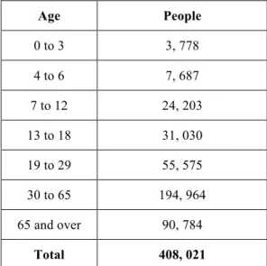
In Ecuador, there are around 400 thousand people with an impairment. Most of the impaired are aged 30 and over. This information is illustrated in the next table.
Age People 0 to 3 3, 778 4 to 6 7, 687 7 to 12 24, 203 13 to 18 31, 030 19 to 29 55, 575 30 to 65 194, 964 65 and over 90, 784 Total 408, 021
7
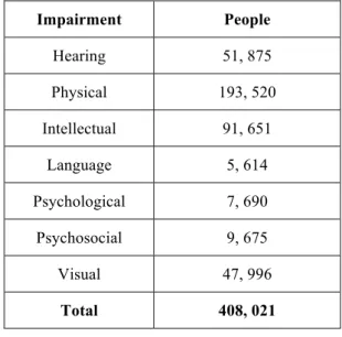
The following chart shows how this group of people is divided by their impairment.
Impairment People Hearing 51, 875 Physical 193, 520 Intellectual 91, 651 Language 5, 614 Psychological 7, 690 Psychosocial 9, 675 Visual 47, 996 Total 408, 021
Table 2.2 - Impairment groups.
In Ecuador, there are around 50 thousand sightless people most of them are 30 and over. Only the 8% of all the impaired have a complete education this results that only the 22% have a regular job.
All this data tells us that most of the blind in Ecuador have a low-income setting. For this cause, acquiring tools for the blind is more difficult for this group. That is why a low-cost solution for sightless people made with easy to obtain materials is needed. This solution must help them with their daily routine.
2.3 IEEE 802.11 wireless LANs
Local-area Networks (LANs) are used to connect data users via wire or cable in local areas that have a few kilometers. The IEEE developed the IEEE 802 standard. This specification provides some rules for communication in small areas. The most famous of these standards is 802.3 or Ethernet. Ethernet used wires to interconnect the data users. [27]
The wireless Ethernet IEEE 802.11 maintains some characteristic of the 802.3 Ethernet standard. The medium of transmission is mushed less reliable than wired media. The propagation properties can be asymmetric and time-varying. Also, lacks full connectivity and user stations may not always be able to hear each other. [27]
The most popular wireless networking technology based on the IEEE 802.11 standard is Wi-Fi. Wi-Fi uses radio waves to provide wireless high-speed Internet and network connections. In Wi-Fi networks, the link between the sender and the receiver is by
8
radio frequency technology (RF). The sender and receiver are provided to an antenna that creates an electromagnetic field that can propagate through the air. [27]
The devices that are compatible with Wi-Fi specification are personal computers, smartphones, video game consoles, cameras, tablets, smart watches. The number of devices that support this standard is increasing day by day.
To provide Internet access and network communications, the Wi-Fi specification uses the Internet protocol suite that is composed of the combination of two protocols Transmission Control Protocol (TCP) and the Internet Protocol (IP). This protocol provides rules to how the transmitted data should be packetized, addressed, transmitted, routed and received. [27]
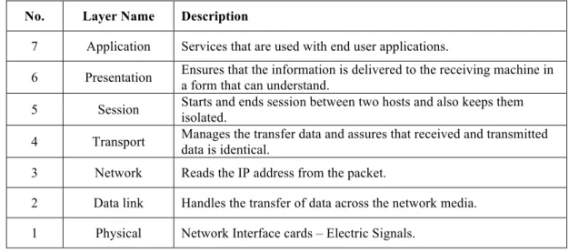
As most of the protocols the Internet protocol suite is structured in layers. Each layer represents data transfer operations. The layers are defined by the Open Systems Interconnect (OSI) Reference Model designed by the International Standards Organization (ISO). The OSI Reference Model defines seven layers that are listed below.
No. Layer Name Description
7 Application Services that are used with end user applications.
6 Presentation Ensures that the information is delivered to the receiving machine in a form that can understand.
5 Session Starts and ends session between two hosts and also keeps them isolated.
4 Transport Manages the transfer data and assures that received and transmitted data is identical. 3 Network Reads the IP address from the packet.
2 Data link Handles the transfer of data across the network media. 1 Physical Network Interface cards – Electric Signals.
Table 2.3 - OSI Reference Model layers.
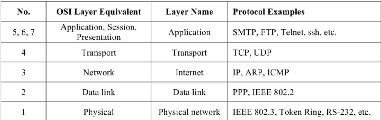
The Internet protocol suite (TCP/IP) uses some of OSI model layers and combines others. The protocol stack of TCP/IP has five layers that are listed below.
9
No. OSI Layer Equivalent Layer Name Protocol Examples
5, 6, 7 Application, Session,
Presentation Application SMTP, FTP, Telnet, ssh, etc. 4 Transport Transport TCP, UDP
3 Network Internet IP, ARP, ICMP 2 Data link Data link PPP, IEEE 802.2
1 Physical Physical network IEEE 802.3, Token Ring, RS-232, etc.
Table 2.4 - TCP-IP Protocol stack.
The Wi-Fi stander uses frequencies between 2.4 GHz and 5 GHz. The range of connection is approximately 50 meters. The data transfer rate is maximum 600 Mbps, but typically is between 150 to 200 Mbps. This depends on the channel frequency and the number of antennas. Latest 802.11-ac standard should offer 500Mbps to 1Gbps. [27]
2.4 Wi-Fi Direct
Wi-Fi Direct is a technology created by the Wi-Fi alliance the primary goal for Wi-Fi direct is to enable a direct device to device communication over Wi-Fi. Wi-Fi direct used the same technology as IEEE 802.11 devices use to communicate with wireless access points. Devices with this technology function as access points and other devices can connect directly to it using WPA2 encryption. [31]
The speed of Wi-Fi direct can reach 100-250 Mbps in a range approximately to 60 meters. The power consumption of a device using Wi-Fi direct depends on the time and range of the connection. [31]
2.5 Bluetooth Low Energy
This technology is popular among gadget makers because the primary operating systems for computers or smartphones support Bluetooth low energy. Making easier for the customers to use the product.
The main differences between Bluetooth 4.0 and the previous versions are: [29] • The client/server architecture was redesigned to ease the implementation and
have lowest cost;
10
• Design for small and discrete data transfers; • Simplification of the discovery and connection.
For a BLE that wants to be visible to the outside world the Generic Access Profile (GAP) is used. GAP controls the links, the advertising in Bluetooth and determines how two devices can or can’t send data to each other. [30]
GAP also defines roles for the devices the primary functions are: [30]
• Central: the device that has the biggest processing power and memory such as mobiles phones, tables, computers;
• Peripheral: devices that are resource constrained and low power that can connect to a more powerful device.
GATT (Generic Attribute Profile) defines the way that BLE devices transfer data between each other. GATT uses Services and Characteristics. This profile makes use of the Attribute Protocol (ATT), a data protocol that is used to store services, characteristics and related data in a table using 16-bits IDs. [30] In BLE connections are exclusive. That means that a BLE peripheral can only be connected to one central device. When the connection is established the device stops advertising itself and is no longer visible. [30]
Bluetooth low energy offers two topologies broadcast network topology and connected network topology. Each one works in a different way and are for different purposes. [30]
Broadcast Network Topology is used to advertise data. This topology is used when the requirements of the BLE device says that has to send data to more than one device at a time. This is possible using the advertising packet. Adding a small amount of custom information in the 31 bytes advertising or scan response payload, the BLE device is able to send data to any devices in listening range. With this topology, the devices can send the same data multiple times to different devices. [30] This topology is illustrated in the image below.
11
Illustration 2.1 - Broadcast topology.
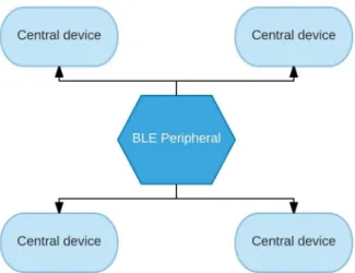
When data needs to be exchanged between BLE devices the Connected Network Topology is used. As soon as the link is established between the peripheral and central device, they can have a both ways communication. A Bluetooth low energy peripheral can only be connected to a BLE central at a time, but the central can be attached to multiple BLE peripherals. [30] The illustration 2.2 shows how this topology works.
Illustration 2.2 - Connected topology.
GATT has clients (phone, table) and servers (peripheral devices). All the transactions are stated by the master device (GATT client), which receives response from the slave device (GATT server). When the connection is establishing, the peripheral will suggest a connection interval and the central device will try to reconnect in that range to see if there is any new data. This time is only a suggestion the central device decides when to reconnect. [30]
GATT transactions are formed by objects called Profiles, Services and Characteristics. The profile is a collection of services and it does not exist in the peripheral. Services are used to break information up into logic entities called characteristics. A
12
service can have one or more characteristics. Each of these services is identified by a unique numeric ID called UUID, which can be 16-bit or 128-bit.
A characteristic encapsulates a single data point. Each characteristic is also defined by a 16-bit or 128-bit UUID. Characteristics also can be used to send data to the peripheral device. [30]
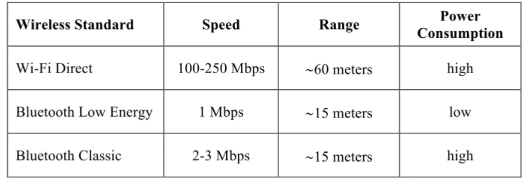
2.6 Bluetooth Low Energy vs Wi-Fi Direct
Each technology has its pros and cons and the one that someone should prefer using in a project depends on the requirements of that project. The following table shows a comparison between this two technologies.
Wireless Standard Speed Range Power
Consumption
Wi-Fi Direct 100-250 Mbps ~60 meters high Bluetooth Low Energy 1 Mbps ~15 meters low Bluetooth Classic 2-3 Mbps ~15 meters high
Table 2.5 - BLE vs Wi-Fi Direct.
2.7 Internet of Things (IoT)
The next step in computer technology will be far from the traditional desktop. A network of interconnected devices gathering and sharing information is the IoT paradigm. New web technologies are being developed to store, process and present a significant amount of data that the interconnected devices will create. [4]
The growing presence of Wi-Fi and 4G-LTE wireless Internet access is vital for creating an IoT network. The devices in these systems will be more than just smartphones and tablets. Such devices will be existing everyday objects that in the past were working in isolation. [4] This growing number of appliances will create a smart environment. This environment will help people to be more productive, healthier and safety. IoT relies on different technologies some of them are listed above. [4]
13
2.7.1 Radio Frequency Identification (RFID)
RFID technology allows microchips to communicate wirelessly. This communication is formed by two parts the reader and the tags. When they are close enough, the transmission will start. [4]
There are passive RFID tags that do not require a battery. These passive tags activate and communicate when a reader is close. This technology is being used in many applications such as transportation, banking, supply chain management. [4]
2.7.2 Wireless Sensors Networks (WSN)
Thanks for the advances in low power integrated circuits and wireless communications now is possible to have small devices for use in remote sensing applications. [4] A Wireless Sensors Networks consist of a wireless network of autonomous distributed devices. These devices use sensors to monitor weather or physical conditions. A WSN also has a gateway that provides connectivity to the devices to gather information from them. [4]
WSN can be applied in a great variety of areas including health care, essential services, and remote monitoring. For basic services such as electricity, street lighting, and water councils, wireless sensors offer a low-cost method for a healthy data collection system that helps reduce energy use and better resource management. In health care, wireless devices make the monitoring of patients and possible health care less invasive. Remote control applications include environmental monitoring of air, water, and soil, structural monitoring for buildings and bridges, industrial monitoring of machines. [4]
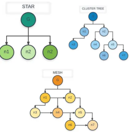
WSN primarily uses three types of network topologies. Star topology, each node connects directly to the gateway. Tree topology, each node connects to a higher hierarchy node in the tree and then to the gateway, data is routed from the lowest hierarchy node in the tree to the gateway. [4] Finally, to provide greater reliability, mesh networks, the characteristic of this topology is that nodes can be connected to multiple nodes in the system and pass the data by the available path of greater reliability. [4]
14
Illustration 2.3 - WSN Topologies.
2.8 Internet of Things Data Protocols
IoT is not a new technology but a defined IoT architecture has not been defined and there is not common agreement in standards and protocols. Making the spread of IoT worldwide difficult. [31] This section show us the most popular protocols for exchanging information in IoT.
2.8.1 CoAP
A synchronous request/respond application layer protocol called Constrained Application Protocol (CoAP) developed by the Internet Engineering Task Force (IETF) is used for information exchange in constrained-recourse devices. [31]
CoAP is a UDP-based application layer protocol. UDP allows CoAP to reduce overhead, the bandwidth requirements and allow CoAP to be unicast and multicast. The client-server architecture is based in the HTTP commands GET, POST, PUT and DELETE to give resource-oriented interactions. CoAP responses can be synchronous and asynchronous. [31]
In order to provide Quality of Service (QoS), CoAP uses four different kinds of messages for the communication: [31]
15
• Confirmable: A message that requires an acknowledgement (ACK). The response can be in a synchronous or asynchronous way;
• Non-Confirmable: Message that not require ACK;
• Acknowledgment: The confirmation of the message reception; • Reset: The received message could not be processed.
CoAP does not includes any built-in security features. Datagram Transport Layer Security (DTLS) can be used to secure the communication. DTLS provides authentication, confidentiality, data integrity and cryptographic. The use of DTLS with CoAP removes to option of multicast. [31]
2.8.2 MQTT
Message Queue Telemetry Transport (MQTT) is a protocol for M2M (machine to machine) communications created by IBM. Uses TCP protocol in an asynchronous publish/subscribe way. In this way clients do not have to request for updates reducing network bandwidth and the use of computational resources. MQTT ensures reliability by using three QoS levels: [31]
• Fire and forget: The message dos not need ACK; • Delivered at least one: The sent message requires ACK;
• Delivered exactly once: A way to ensure that the message was received at least once using four-way handshake.
Using a publish/subscribe architecture MQTT lower the bandwidth and the processing extending the battery life of the devices. To provide security MQTT uses TLS/SSL (Secure Sockets Layer). [31]
2.8.3 XMPP
XMPP (Extensible Messaging and Presence Protocol) is an old protocol that is widely use all over the Internet. Uses TCP and provides two different systems: request/response (synchronous) and publish/subscribe (asynchronous). XMPP was designed for real-time communications and provides low latency exchange and small footprint. [31]
XMPP ensures reliability using the TCP mechanism and do not provide QoS options. TLS/SSL is used to give security to XMPP. In XMPP the messages are in XML (eXtensible Markup Language) format that creates an overhead and the devices need
16
additional computational power to process the message leading to more power consumption. [31]
2.8.4 Restful Services
The architectural style Representation State Transfer (REST) is widely used all over the internet. REST uses the methods GET, POST, PUT and DELETE from HTTP to exchange messages in a synchronous request/respond way. The message contains the header of HTTP and the content can be XML or JSON (JavaScript Object Notation). This style can be easily configured in all operating systems and all M2M cloud platforms support it. [31]
REST uses TLS/SSL for security. The use of HTTP means that REST does not support constrained-communication devices and only can be used for final applications. CoAP is a light version of REST that has the capability to be used in constrained resource devices. [31]
2.8.5 AMQP
Financial industry uses the TCP based Advance Message Queuing Protocol (AMQP). This protocol provides an asynchronous publish/subscribe communication. The key feature of this protocol is to ensure the reliability even after network problems. The messages that AMQP uses are:
• At most once: The message is sent one time if does not matter if was received or not;
• At least once: The message will be received at least one time; • Exactly once: The message will be received at exactly one time.
AMQP uses TLS/SLL for security. The success rate of this protocol depends of the bandwidth. Low bandwidth means low success rate. [31]
2.8.6 Websocket
Websocket is a protocol based on TCP. Was created as a part of HTML 5 for message exchange in an asynchronous full-duplex connection. The handshake is similar of HTTP but after the connection is stablished the HTTP header are removed and the devices can communicate in real-time and full-duplex way. [31]
17
This protocol runs over the reliable TCP and implements no reliability mechanisms by its own. If required, the communication can be secured using the Websocket over TLS/SSL. A sub-protocol of Websocket provides a publish/subscribe system and is called WAMP (Websocket Application Messaging Protocol). [31]
This protocol was not designed for the use in resource constrained devices. However, was designed for real-time communication, Websocket is secure, minimizes overhead and with the use of WAMP can provide efficient communication. [31]
2.9 Assistive Technologies
Many teams for different parts of the world have been developing different systems with the purpose of help visual impaired with their daily lives. One of these solutions is an information system based on location data used to guide blind people, called BlindeDroid. BlindeDroid is a software library in Java for Android mobile devices. The team developed a prototype based on this library and tested it on a shopping center with two blind people.
The prototype gathers the information required importing XML files from beacons placed in strategic locations inside a building. With this information, the prototype helps the user with guided navigation, answering questions and providing objective information about places, products, and services near the user. The system gives the possibility to create a personal beacon network with information such as stores, services, houses. The system a significant number of tags to successfully help their user with the navigation. Although this drawback, BlindeDroid was able to help the testers to reach their desired location in the test perform by the research team [6].
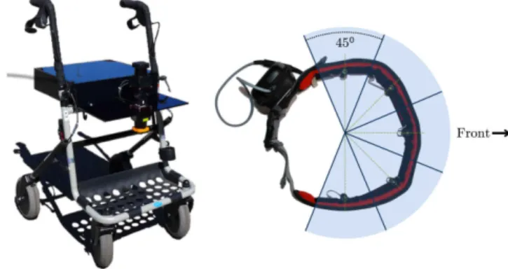
In [7] the authors propose a smart walker that helps visually impaired people with walking disabilities. This research team decided to elaborate this prototype because almost all the products for visually impaired are not meant to be for people with walking problems. The prototype is a walker that does not only provide walking assistance but also helps the user avoiding obstacles. The system detects obstacles such as curbs, staircases, and holes in the ground and transmits obstacle proximity information through haptic feedback.
The positive and negative obstacle detection is performed by two lasers. The data from this laser is combined and processed by a central computing device. When an obstacle is detected is transmitted via Bluetooth to a belt that the user is wearing. This belt
18
has five vibrating motors to provide haptic feedback. Each engine covers 45 degrees; all combined makes a total of 225 degrees of coverage.
The authors tested a prototype of the smart walker at SightCity 2014 in Germany. They received positive feedback. The tester said that the smart walker makes them feel safe. The prototype successfully detected all the obstacles in the test. The illustration below shows the smart walker prototype with the haptic belt.
Illustration 2.4 - Smart Walker and haptic belt.
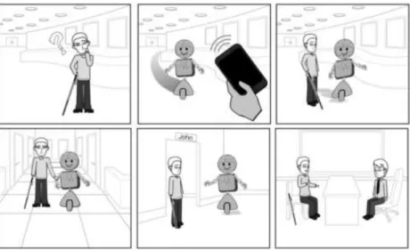
In the paper [8] the authors sought to design specifications that detail how to build a service robot that could interact and guide a visually impaired person through a building in an efficient and socially acceptable way. The research team said that robots are becoming more common in large buildings like hotels, stores and airports. As bear out in [23], that tells us about a robot officer used for patrolling city’s malls and tourist attractions in Dubai. A robot officer is a great tool for police as it can broadcast any incident directly to headquarters, helping with a quick response.
The authors of [8] conducted participatory design sessions with three designers, two of them with vision disability and five visually impaired non-designers. Authors assure that using a robot for indoor navigation has two main advantages. Interacting with robots will require minimum training. The robot will provide information depending on the needs of the person that is requesting help. It can only provide directions for people that are familiar with the environment or escort the person. The escort action can be walking next to the visually impaired or slightly ahead; this depends on user comforts.
Second, they assume that robots will be designed for multiple activities and they will require minimum changes to assist blind people. At the end of this study, the authors developed design recommendations for a blind people guiding the robot. They hope that their study will inspire robotics researchers to make a prototype. Illustration 2.3 shows the interaction between a blind person with the guiding robot.
19
Illustration 2.5 - Guiding robot.
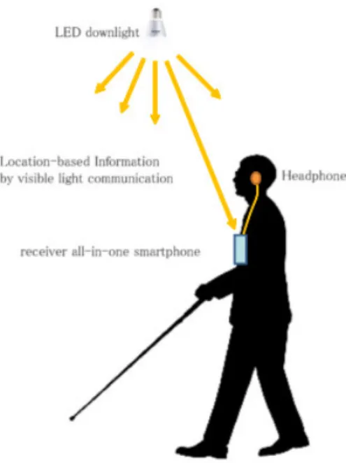
Another indoor navigation system for sightless people uses visible light communication [9]. In this system, LED lights, a smartphone with integrated Bluetooth, a visible light receiver and headphones were used for the implementation. The system employs LED lights and a geomagnetic correction method [9].
Each LED light has an identifier. The light ID is sent via a light communication channel to the smartphone receiver. This receiver transmits the ID of the LED to the phone via Bluetooth. Using the LED light, the phone receives the positional data from a cloud service, via Wi-Fi. The positional information is combined with the guidance content into audio files and transmitted to the user’s headphones [9].
A big challenge for this project is to identify the direction of the user inside a building. The authors used the geomagnetic sensor of the smartphone, but the data were coming from this device can be distorted by in indoor spaces. They make corrections using geomagnetic data taken in advance for each LED light.
The prototype was tested with six volunteers inside a building. Three of them with low vision and three blind. The volunteers had to travel from the reception of the building to the toilets. The average time that the volunteers take to reach destination was five minutes. After the test, an interview with each subject was conducted. All the volunteers told the interviewer the system needs to be more accurate in the direction and fix the timing of the guidance. As conclusions of the publication, the authors said that the prototype could guide a person inside an unknown building, but a better system for detecting the direction in indoors is required. The system also lacks of the ability of detecting obstacles that is an important feature for all guiding systems. The following illustration shows how the system works.
20
Illustration 2.6 - Indoor navigation using visible light.
The authors of paper [10] developed a camera-based assistive text reading framework to help visually impaired read text labels and products packaging from hand-held objects in their daily lives. The recognition software locates the text region and distinguishes the words. The recognized text codes are output to blind users in an audio form [10].
The proposed system uses a new way of detecting the region of interest by isolating the object using movement. The user has to shake the object with this the systems identify the object that has to read the text. This approach is helpful in environments like supermarkets or shopping malls. Different kinds of algorithms for detecting text are implemented in this device. The reason of this is because commercial products use different patterns for labeling their products to be more attractive to possible consumers.
The experiments performed in the recognition software demonstrate that achieves state of the art. The authors found interface issues and some problems in extracting and reading text from different objects with complex backgrounds [10].
Virtual Eye uses GPS for helping sightless people [11]. The prototype consists of a GPS receiver, GMS module, a microcontroller (ATMEGA 328), an ultrasonic sensor, a speech IC and headphones [11]. When the ultrasound sensor finds an obstacle, sends the information to the microcontroller. The microcontroller processes the data and when an obstacle is found a signal is forwarded to the speech IC.
21
The speech IC inform the user that an obstacle is detected by a sound. The GPS information is continuously sent to the microcontroller. The microcontroller transmits the location using the GSM modem in SMS format to all saved numbers. If a familiar of the blind person wants to know where the user is can send a text message to the device number and the system will answer with a text message with the coordinates of the blind person.
This system uses low-cost materials that can be acquired easily. The primary goal of the authors is making an inexpensive solution for visually impaired. As reported in the begging of the present chapter a large quantity of the blind population around the world lives in a low-income setting.
In [21] the authors created a virtual eye system for guiding users in indoor and outdoor. Their system consists of two cameras mounted in the forehead of the user. The cameras transmit real-time video through a USB connection to a DPU (Data Process Unit) in this case the authors used a laptop. The laptop has a real-time recognition software. The prototype can detect and identify free paths, moving obstacles that may interfere the free path, stairs, crosswalk and traffic lamps.
Before the recognition process takes place. The images from the cameras pass a preprocessing stage. This stage has three parts image acquisition, rectification, and stabilization. This process improves the accuracy of the detection. The recognition workflow starts with the free path identification. The open path detection algorithm compares similar pixels in the bottom part of the image identifying the route that the user is following in a few meters ahead. This algorithm is not perfect caused by head movements and holes in the path; the authors encourage to find a more robust algorithm.
After that, the system starts identifying ground level. The purpose of ground level detection is to eliminate walls and objects that are not on the ground level. The algorithm makes the assumption that the ground is the large plane of the image. In the majority of the cases, this is true except when the user is in front of a wall. With the ground level detected the prototype could start identifying stairs and crosswalks. Once a stair or crosswalk is discovered the program starts looking for traffic lights.
All the processed information is transmitted to the user using audible alerts. The designers reduced the signal generation as low as possible. The reason of this is because visually impaired rely mostly on their hearing.
22
The authors tested the system and concluded that the system needs about two minutes of training. They tested the solution with visually impaired people, and most of them gave positive feedback. A small group said that the solution is loud and depriving.
BIOH uses ultrasound in order to detect obstacles [22]. This ultrasound system is placed in the forehead of the user. When an obstacle is detected, the system gives a pressure warning in the forehead of the user. The intensity of the pressure depends on the distance to the obstacle.
The prototype can be combined with a GPS and 3G module. This module offers the possibility to add a SOS button. When the user needs help can press the buttons and the system sends a text message with the location of the user to predefined numbers.
The authors believe that the system can be improved using solar energy for places with lower accessibility.
Another study related to this project is Smart Vision. Smart Vision consists of an ARM7 LPC2148 microcontroller, a camera, a computer, a GPS and a speaker. The focus of this study is the development of a computer vision module for Smart Vision. The system uses synthetic vision to detect obstacles that are alerted to the user through audible signals [24].
GPS (Global Positioning System) is used for outdoor navigation. Coordinates of several locations are stored in the microcontroller, and when the user reaches the desired position, he/she will be alerted by the speaker [24]. Smart Vision showed that it could detect obstacles by helping the blind to move without help from another person [24].
A study for blind people following a path indoors using the camera of a smartphone is presented in [25]. Eight visually impaired volunteers participated in this study. In which three different tests were performed to find markers with the camera of the smartphone [25].
The authors used readily detectable markers that did not require a significant computational processing [25]. As conclusions of this study, the authors highlight three aspects. The limited field of view of the camera of the smartphone caused the scan to be more active, which is hard for some people. Some of the participants found uncomfortable carrying the cell in their hand so the authors recommend exploring the option of cameras that can be attached to the body [25].
23
Finally, it was found that despite using markers for easy detection find them can take quite a while in certain environments. This means that the setting and location of markers is essential [25].
In [26] the authors explore different ways of making visual maps to be used by blind people. They give as an example of a website to book hotels. In which you enter the dates of stay, and the city you want and the page show on a map the hotels that exist in the place [26].
To make this page accessible, the authors recommend small modifications to existing functions. For example, when the mouse passes a hotel the name and information are displayed. You can add audio with the same information.
By adding compatibility with touch screens, the web page can be easily accessed [26]. The authors state that their study may be the starting point for creating new technologies for the blind [26].
There are many systems related to the works presented in this work. We believe that our blind guide solution has extra value than the rest as it uses an image recognition software that will help sightless people to understand their surroundings. We also pretend to give social skills to the systems to create a database that stores the location of the obstacles and make it available to the rest of the users of our system.
2.10 Synthesis
In this chapter, a study of the scientific knowledge in the area of the IoT was carried out, in which this work is based. It was intended to make known the challenges and possible solutions and trends.
In the first part of the chapter, statistics about the reality of visually impaired in the world and Ecuador. There is around 285 million of the blind, most of them are aged above fifty and live in low-income settings. This first part contains the most common diseases that cause visual impairment, some of them are treatable, but for lack of resources, people don’t have access to medical resources.
The second part of the chapter was about the concept of IoT and the technologies on which it is based and relies on. The section includes the description of Wi-Fi and Wi-Fi Direct and how these technologies help in the communication device to device, an essential part of IoT. Bluetooth Low Energy is another technology focused in resource constrained
24
devices that help in their communication. The differences of Wi-Fi Direct and Bluetooth Low Energy was described. Each technology has their advantages and disadvantages, and the main reason for choose one or another is the requirements for the project.
IoT has a many data protocols that help devices communicate with others. Each protocol provides communication in different ways, the next table is a summary of the data protocols of this chapter. [31]
Protocol Transport QoS options Architecture Security
CoAP UDP YES Request/Response DTLS MQTT TCP YES Publish/Subscribe TLS/SSL XMPP TCP NO Request/Response Publish/Subscribe TLS/SSL REST HTTP NO Request/Response HTTPS AMQP TCP YES Publish/Subscribe TLS/SSL Web socket TCO NO Publish/Subscribe Client/Server TLS/SSL
Table 2.6 - Major differences IoT data protocols.
Radio Frequency Identification (RFID) and Wireless Sensors Networks (WSN) are technologies that their goal is to extend the functionality of ordinary objects and create a network of this objects with the purpose of generating valuable information.
For the final part of the chapter, publications of new technology that aims to help visual impaired people was presented. The publications are from research teams all over the worlds. These new inventions are based on the IoT that aims to create a portable device for helping blind people in their daily routine. This project collects all the successes and recommendations of these publications to create a useful device for the blind.
The next chapter talks about the different devices that forms part of the Blind Guide system, how these devices work and how they communicate between each other.
25
26
3
Implemented
Technologies
In the last chapter was presented the real situation for visually impaired in Ecuador and all over the world and how research teams are developing new technology based on the IoT. These solutions aim that blind can live better and be more active.
Blind Guide uses as foundations the knowledge acquired from the works of the research teams presented in the previous chapter. Blind Guide takes a step further. The system is portable solution, easy to use and to carry. It helps sightless people to navigate in unknown scenarios reducing the danger of a fall or an accident. The system performs well in outdoor or indoor scenarios. The system ensures that the user can use it at any time and in anywhere.
Blind Guide uses echolocation, the same ability that some animals have in order to capture their prey of travel in the dark without crashing. The system uses the small sensor that is distributed in the body of the user. There I two types of sensors in Blind Guide. One that has ultrasounds in order to find obstacles and a central sensor that gathers all the information of the ultrasounds for giving feedback to the user.
This new chapter lists all the electronic parts used in each device and the technologies implemented to make all the parts work together. The first part of this chapter talks about how each part of the system works and interact with each other. After that, the peripheral devices of the solution are presented and the technologies that are used in this sensor. Finally, we explain what is and how the main sensor of Blind Guide works.
27
3.1 Proposed Solution
The goal of the present project is to create a system that can be accessible for everyone. The electronic parts used in the Blind Guide prototype are easily obtainable using affordable off-the-shelf components available worldwide. The system is formed by two elements. The peripheral sensor that searches for obstacles in real time. Blind Guide can use the number of peripheral sensors as needed. These sensors can be attached to any part of the body. The recommended way is to use four sensors. One in the head, one in the chest and one in each leg. This configuration maximizes the obstacle detection. Different configurations can be used to work with another device like the white cane. In this case, only the sensors in the head and the chest, are needed to extend the range of action of the white cane.
The order part of the system is the central device. The central gathers the information sent wirelessly by the peripheral sensors. Process that information and if an obstacle is found uses a camera module to take a picture of the obstacle. The obstacle picture is sent to an image recognition cloud service. The service responds with the possible names of the obstacle. This information is transmitted to the user using a speaker.
3.2 Peripheral sensor
The primary function of the external sensor is to find nearby obstacles and alert wirelessly the central device. The sensor is formed by an ultrasound detector and a Wi-Fi microcontroller. Each external sensor has a 500 mA LiPo (Lithium Polymer) battery. A prototype of this sensor is illustrated in Figure 3.1.
28
The schematics for this device is in the next picture.
Illustration 3.2 – Wi-Fi peripheral schematics.
A variation of the peripheral sensor that uses Bluetooth Low Energy instead of using a Wi-Fi microcontroller is also implemented. Uses the same ultrasound and battery but this BLE sensor uses the HM-10 Bluetooth 4.0 for making the communication with the central device. Also, an Arduino nano module is used in order to process the data. A picture of this BLE peripheral devices is in the next picture.
29
The schematics for this device is in the following illustration.
Illustration 3.4 - BLE peripheral schematics. 3.2.1 Ultrasonic sensor
For the purpose of detecting obstacles and ultrasonic sensor is used. The ultrasound transmitter emits a 40KHz ultrasonic wave that travels through the air and immediately returns if an obstacle is in the range of 2cm-400cm [12]. This effect is shown in the Illustration 3.2. The ultrasound system calculates the distance between the sensor and the obstacle and sends the data to the microcontroller. The sensor operates with a current of 15mA, and the cost of acquisition is very low [12].
30
3.2.2 Wi-Fi microcontroller
To send the information wirelessly if an obstacle is detected by the central a microcontroller with a Wi-Fi module was used. This microcontroller uses an 80 MHz ESP8266 processor with a Wi-Fi front-end that supports TCP/IP and DNS [13]. The microcontroller has a 3.3V out and a 500mA regulator [13].
The ultrasound sensor continuously sends data to the microcontroller. The microcontroller only alerts the central when the distance of the obstacle is less than the signal range configured in the microcontroller. The warning distance varies depending on which part of the body is placed the peripheral sensor. The reason for this configuration is because we want to limit the power consumption as much as possible.
Illustration 3.6 - Wi-fi microcontroller. 3.2.3 Bluetooth Low Energy Module (HM-10)
The HM-10 is a 3.3v small Bluetooth low energy module based on the TI CC2540 or CC2541 from Texas Instruments. The HM-10 is developed by JNHuaMao Technology Company and is one of many Bluetooth devices the company produces. [32]
This HM-10 module works with +2.5v to +3.3v. Requires up to 50mA, uses around 9mA when is active and in sleep mode uses 50-200uA. HM-10 is compatible with Bluetooth 4.0. [32]
HM-10 has a group of services, and each service has a set of characteristics. The module works by setting the value of the custom characteristic to the value of the information to be transmitted. HM-10 then sends out a notification to the remote device to inform that new data is available. [32]
31
Illustration 3.7 - HM-10 module. [32] 3.2.4 Peripheral Devices Power Consumption
Each type of peripheral device uses different technologies and the power consumption is different for each device. In the chart below is a comparison of each device power consumption.
Module Wi-Fi peripheral BLE peripheral
Ultrasound ~15mA ~15mA Bluetooth low energy - ~9mA
Wi-Fi module ~150mA -
Arduino nano - ~19mA
Battery 500mAh 500mAh Consumption 165mAh 43mAh
Results ~3 hour of battery life ~12 hours of battery life
Illustration 3.8 - Peripherals battery consumption.
As illustrated in the previous table with a 500mAh LiPo battery the BLE peripheral has around twelve hours of batty life. In contrast, the battery life of the Wi-Fi peripheral reach only for three hours. As shown in previous chapters Wi-Fi technology consumes more battery rather than Bluetooth low energy. Wi-Fi also has advantages the range of the connection can reach up to 60 meters. BLE devices can only reach 15 meters. The requirements of the Blind Guide prototype is to have the peripheral devices attached to the body of the user for this reason BLE peripheral device is more suitable for goal of this project.