Ana Carolina Simões Monteiro
Assessing Initial Embodied Energy in
Building Structures using LCA
Methodology
Dissertation to obtain the Master Degree in Civil Engineering
Supervisor: Miguel Pires Amado, Assistant Professor
with aggregation, Faculdade de Ciências e Tecnologia
da Universidade Nova de Lisboa
Co-supervisor: Søren Wandahl, Senior Associated
Professor, Civil and Architectural Engineering
Department, Aarhus Universitet
Assessment Comitte:
Chair: Professor Dr. Daniel Aelenei
Examiner: Professor Dr. Manuel Duarte Pinheiro
Examiner: Professor Dr. Miguel Pires Amado
“Copyright” Ana Carolina Simões Monteiro, of FCT and of UNL.
ACKNOWLEDGMENTS
First of all, I would like to express my sincere gratitude to Professor Søren Wandahl
for accepting to be my co-supervisor and guiding me during my Erasmus stay at
Aarhus Universitet. It was a pleasure to work and learn with Professor Søren. I also
would like to express my deepest gratitude to Professor Mads Olesen form Aarhus
Unversitet for the help provided in the empirical part of my research. Professor Mads
performed the structural analysis and defined the structural system used in my
thesis to assess initial embodied energy.
Secondly, I want to express my gratitude to Professor Miguel Amado for being my
supervisor and for giving me freedom to choose the theme for my thesis. Despite
being distant, when I was in Denmark, Professor Miguel always supported me and
helped me when I need.
Then, I would like to give a special thanks to Engineer António Carrasquinho de
Freitas for all his friendship and help during these last two years of studies. Thank
you very much, without your support I could not make it so far as I did.
I also want to thank to my dearest boyfriend and now fiancé for encouraging me to
do my thesis abroad and for all his support and love. To all my friends and faculty
colleagues Dione Guimarães, Laís Andrade Viana, Joana Guerreiro, Carla Veiga
and Filipa Miguel, thank you for being such good friends and for all the group works
and study hours that we have been together.
Last, but not least, I want to express my entire gratitude and love to my family,
especially to my parents for the education provided. Thank you for making this
ABSTRACT
The considerable amount of energy consumed on Earth is a major cause for not achieving sustainable development. Buildings are responsible for the highest worldwide energy consumption, nearly 40%. Strong efforts have been made in what concerns the reduction of buildings operational energy (heating, hot water, ventilation, electricity), since operational energy is so far the highest energy component in a building life cycle. However, as operational energy is being reduced the embodied energy increases. One of the building elements responsible for higher embodied energy consumption is the building structural system. Therefore, the present work is going to study part of embodied energy (initial embodied energy) in building structures using a life cycle assessment methodology, in order to contribute for a greater understanding of embodied energy in buildings structural systems. Initial embodied energy is estimated for a building structure by varying the span and the structural material type. The results are analysed and compared for different stages, and some conclusions are drawn. At the end of this work it was possible to conclude that the building span does not have considerable influence in embodied energy consumption of building structures. However, the structural material type has influence in the overall energetic performance. In fact, with this research it was possible that building structure that requires more initial embodied energy is the steel structure; then the glued laminated timber structure; and finally the concrete structure.
RESUMO
A considerável quantidade de energia consumida na Terra é uma das maior causas para não se alcançar desenvolvimento sustentável. Os edifícios são responsáveis pelo maior consumo de energia a nível mundial, cerca de 40%. Grandes esforços têm sido feitos, no que diz respeito à redução da energia operacional dos edifícios ( aquecimento, água quente, ventilação, eletricidade), devido ao facto de a energia operacional ser, até agora, a componente com maior consumo energético no ciclo de vida de um edifício. Contudo, à medida que a energia operacional vai sendo reduzida, a energia incorporada aumenta. Um dos elementos de um edifício responsável pelo maior consumo energético corresponde ao sistema estrutural. Por este motivo, o presente estudo vai estudar parte da energia incorporada (energia incorporada inicial) da estrutura de um edifício, através do uso da metodologia de avaliação de ciclo de vida, variando a distância entre pórticos e o tipo de material estrutural. A energia incorporada inicial é estimada para uma estrutura de edifício variando a distância entre os pórticos e o tipo de material estrutural. Os resultados são analisados e comparados para diferentes fases, e algumas conclusões são retiradas. No final deste trabalho foi possível concluir que a variação da distância entre pórticos estruturais não é significante no consumo de energia incorporada de estruturas de edifícios. Porém, o tipo de material estrutural tem influência no desempenho energético total. De facto, com esta pesquisa foi possível concluir que a estrutura de edifício que utiliza mais energia incorporada inicial é a de aço, seguida da de madeira, e, por fim, da de betão.
TABLE OF CONTENTS
1. INTRODUCTION ... 1
1.1
B
ACKGROUND... 1
1.2
M
OTIVATION... 2
1.3
O
BJECTIVES... 3
1.4
R
ESEARCHP
ROCESS ANDM
ETHODOLOGY... 3
1.5
T
HESISO
RGANIZATION... 5
2. METHODOLOGY TO ASSESS ENERGY IN BUILDINGS ... 7
2.1
I
NTRODUCTION... 7
2.2
L
IFEC
YCLEA
SSESSMENT(LCA) ... 7
2.2.1 Life Cycle Assessment (LCA) Methods ... 9
2.2.2 Life Cycle Assessment (LCA) Tools ... 11
2.2.3 Sophistication Level of Life Cycle Assessment (LCA) ... 11
2.3
L
IFEC
YCLEE
NERGYA
NALYSIS(LCEA)
IN THEB
UILDINGI
NDUSTRY... 12
2.3.1 Identifying Life Cycle Energy (LCE) Requirements ... 14
2.3.2 Embodied Energy (EE) vs Operational Energy (OE) ... 19
2.3.3 Problem Statement ... 20
3. THE MANUFACTURE PHASE OF STRUCTURAL BUILDING MATERIALS ... 23
3.1
I
NTRODUCTION... 23
3.2
T
HEP
RODUCTS
TAGE... 25
3.2.1 Concrete raw material extraction and production ... 26
3.2.2 Steel raw material extraction and production ... 28
3.2.3 Timber raw material extraction and production ... 30
3.3
T
HEC
ONSTRUCTIONS
TAGE... 33
3.3.1 Transportation ... 33
3.3.2 On-‐site construction equipment ... 34
4. CASE STUDY REVIEW OF EMBODIED ENERGY IN BUILDING STRUCTURES ... 37
4.1
I
NTRODUCTION... 37
4.2
C
ASES
TUDIES... 38
4.3
C
ASE STUDIES DISCUSSION... 43
5. UNDERSTANDING VARIATIONS IN EMBODIED ENERGY VALUES ... 51
5.1
I
NTRODUCTION... 51
5.2
D
IRECTD
RIVERS... 51
5.2.1 Embodied Energy Data ... 51
5.2.2 Subjectivity in LCA Methodology ... 53
5.3
I
NDIRECTD
RIVERS... 53
5.3.1 Insufficient Documentation in Literature Review ... 53
6. ASSESSING INITIAL EMBODIED ENERGY IN BUILDING STRUCTURES ... 55
6.1
I
NTRODUCTION... 55
6.2
D
EVELOPEDM
ETHODOLOGY... 55
6.2.1 Structural Analysis ... 56
6.2.2 Performed LCA ... 58
6.3
I
NITIALE
MBODIEDE
NERGYC
ALCULATIONS... 59
6.3.1 Product Stage Calculations ... 60
6.3.2 Construction Stage Calculations ... 63
7. EMPIRICAL RESULTS DISCUSSION ... 69
7.1
I
NTRODUCTION... 69
7.2
I
NITIALE
MBODIEDE
NERGYR
ESULTSD
ISCUSSION... 69
7.2.2 Construction Stage Energy Consumption Discussion ... 71
7.2.3 Total Initial Embodied Energy Consumption Discussion ... 75
7.3
M
ETHODOLOGICALL
IMITATIONS... 80
8. CONCLUSIONS AND FUTURE DEVELOPMENTS ... 83
8.1
C
ONCLUSIONS... 83
8.2
F
UTURED
EVELOPMENTS... 84
REFERENCES ... 85
APPENDIX ... 91
LIST OF TABLES
Table 4.2.1 – Case study 1 embodied energy values.……….38
Table 4.2.2 – Case study 2 embodied energy values……….…………...39
Table 4.2.3 – Case study 3.1 embodied energy values……….……..40
Table 4.2.4 – Case study 3.2 embodied energy values……….…..40
Table 4.2.5 – Case study 4 parameters……….…….41
Table 4.2.6 – Case study 4 embodied energy values……….…...41
Table 4.2.7 – Case study 5 embodied energy values………..…42
Table 4.2.8 – Case study 6 embodied energy values………..42
Table 4.2.9 – Case study 7 embodied energy values………..43
Table 4.3.1 – Case studies inclusion or exclusion of manufacture phase life cycle stages………...44
Table 6.2.1.1 – Maximum dimensions for beams spans and columns heights defined for the building structure………...…57
Table 6.2.1.2 – Characteristics of structural materials defined for the building structure………...58
Table 6.2.2.1 – Manufacture phase unit processes considered for the performed LCA………...59
Table 6.2.2.2 – LCI database sources………...60
Table 6.3.1.1 – Embodied Energy Coefficients………..………..61
Table 6.3.1.2 – Materials weight……….61
Table 6.3.1.3 – Embodied energy calculations for concrete structure product stage………….61
Table 6.3.1.4 – Embodied energy calculations for steel product stage……….…...62
Table 6.3.1.5 - Embodied energy calculations for timber product stage………..………62
Table 6.3.2.1 – Vehicle energy consumption………....64
Table 6.3.2.2 – Embodied energy calculations for concrete structure transportation………….64
Table 6.3.2.3 – Embodied energy calculations for steel structure transportation………….…..65
Table 6.3.2.4 – Embodied energy calculations for steel structure transportation…………...…65
Table 6.3.2.5 – Work capacity and energy consumed by equipment for concrete structural works………...66
Table 6.3.2.6 – Work capacity and energy consumed by equipment for steel structural works………..………....…..66
Table 6.3.2.7 – Embodied energy calculations for on-site concrete equipment for concrete structure……….………...67
Table 6.3.2.8 – Embodied energy calculations for on-site concrete equipment for steel structure……….………..67
LIST OF FIGURES
Figure 1.1.1 – Urban population growth in urban and rural areas, 1950-2050………..2
Figure 1.4.1 – Analogy to the research process………..…...3
Figure 1.4.2 – Adopted Methodology………...4
Figure 1.5.1 – Thesis Structure………...5
Figure 2.2.2 – Life Cycle Assessment………..7
Figure 2.3.2 – Life cycle assessment framework………...8
Figure 2.4.1 - Life cycle energy analysis and respective system boundaries………..……14
Figure 2.3.2.1 – Relation between operating and total energy………..19
Figure 2.3.3.1 – Concrete structural frame………21
Figure 2.3.3.2 – Timber structural frame………..….21
Figure 2.3.3.3 – Steel structural frame………...21
Figure 3.1.1 – The energy system diagram of building manufacture phase………....23
Figure 3.1.1. 2 – Life cycle energy manufacture phase stages………..24
Figure 3.2.1.1 – Process flow diagram for the cement manufacturing………..27
Figure 3.2.2.1 – Process flow diagram for the steel manufacturing………..30
Figure 3.2.3.1 – Process flow diagram for the glued laminated timber manufacture process………..…..32
Figure 3.3.1.1 – Concrete mixer lorry……….34
Figure 3.3.1.2 – Flat deck semi-trailer lorry………..….34
Figure 4.3.1 – Case studies product stage embodied energy consumption……….…...45
Figure 4.3.2 – Case study construction stage embodied energy consumption……….………..47
Figure 6.2.1.1 – Building structural frame defined to perform initial embodied energy calculations……….……56
Figure 7.2.1.1 – Embodied energy variation in the building structure during the product stage, in function of span and material type……….69
Figure 7.2.2.1 – Embodied energy variation for the building structure during transportation, in function of span and material type………..….72
Figure 7.2.2.2 – Embodied energy variation in the building structure during on-site equipment, in function of span and material type………...72
Figure 7.2.2.3 – Embodied energy variation in the building structure during the construction stage, in function of span and material type………....74
Figure 7.2.3.1 – Initial embodied energy consumed per span in the concrete structure………75
Figure 7.2.3.2 – Initial embodied energy consumed per span in the steel structure…………..76
Figure 7.2.3.3 – Initial embodied energy consumed per span in the timber structure…….…..77
LIST OF ABBREVIATIONS AND SYMBOLS
Abbreviations
BEES – Building for environmental and economic sustainability BESLCI – Building energy system life cycle inventory
BOS – Basic oxygen steelmaking CaCO3 – Calcium carbonate
CaO – Calcium oxide CO2 – Carbon dioxide DE – Demolition energy EE – Embodied energy
EIO-LCA – Economic Input-Output Life Cycle Assessment GHG – Green house gases
HVAC – Heating, ventilation and air conditioning ICE – Inventory of Carbon & Energy
I-O – Input –Output
ISO – International standards organization LCA – Life cycle assessment
LCE – Life cycle energy
LCEA – Life cycle energy analysis LCI – Life cycle inventory
OE – Operational energy
OPC – Ordinary Portland cement
Symbols
Roman Letters
𝐶!!- Capacity for work per hour of equipment k
𝐷! !
- Duration of equipment k usage
EC – Energy required for building construction
𝐸𝐶!! – Energy consumption per kilometer of vehicle j for a ton or cubic meter of material i
𝐸𝐶!! - Energy consumption per hour of equipment k
EC_E – Energy required to construction equipment
EC_T – Energy required to transport building materials from the plant to the construction site ED – Energy for destruction of the building
EM– Energy required for material manufacturing EOA – annual operating energy
ET – Energy for transportation of waste material EEi – Initial embodied energy
EEr – Recurring embodied energy of the building fck – Concrete strength class
fyk – Steel strength class gk– Permanent dead load Lb – Life span of the building
Lmi– Life span of the building material
mi – Quantity of building material required to produce a building Mi – Energy content of material per unit quantity
qk – Daily use load
𝑄! –Quantity of material i
𝑇𝐷! !
– Transportation distance of the building material i from the plant to the construction site
using vehicle j
Greek Letters
1. Introduction
This chapter presents the background and motivation that support this study. The objectives of the study
are presented, and it is explained the research process and methodology used. Finally, it is presented an
overview of the thesis structure.
1.1 Background
The depletion and mismanagement of resources combined with the pollution is accentuating the global warming effects. Therefore, the sea level is rising and the world is facing alarming numbers of greenhouse-gases (GHG) and energy consumption.
Over the last decades the term sustainable development has been one of the most discussed topics in our society. In one hand, there is a demanding concern with environmental issues in order to preserving the Earth for the present generation, but also for the next ones. On the other hand, the population growth is expected to increase rapidly in the near future. Between 2011 and 2050 it is estimated an increase of 2,3 billion people (UnitedNations, 2014). In consequence, the social and economic activities will become more competitive. Associated with the population growth is associated a larger consumption of water, food, energy, and materials and higher values of waste production and CO2 emissions.
Currently, more than half of world’s population is living in cities and more and more people are expected to migrate from the rural areas to the urban areas, as it is possible to observe per figure 1.1.1.
This means that the population growth for the next decades will take place in cities. Consequently, it will be necessary to create more industries, transport systems and buildings to meet the increasing number of population in urban centres, which will raise the energy consumption. In fact, this situation is expected to complicate in the following years if no action is taken.
Buildings are essential for the major socio-economic development of any nation, however they have serious negative environmental impacts in our planet. It is indeed necessary to promote the life quality of the populations without compromising the life quality on Earth. This goal can be achieved by implementing sustainable construction.
With sustainable construction it is intended to achieve sustainable development within building industry. To reach this goal, policies that promote sustainability are being implemented all over the world. In fact, recently new standards and methodologies that use a life cycle approach to evaluate buildings environmental impact have emerged. According to the United Nations Environment Programme (UNEP), the use of these methodologies can reduce the energy consumption in buildings from 80 to 30%.
1.2 Motivation
The main reason to carry out this research drives from the environmental problems that the building industry is currently facing. So far, there have been some considerable improvements to achieve sustainable construction in the building industry; further investigation is needed in order to solve the new challenges and to reach the goals established by political organizations.
It was decided to focus the research on buildings’ energy consumption for two main reasons:
• The most significant environmental impact in the building industry is due to the higher energy consumption;
• It was found an opportunity to reduce energy consumption in buildings through the investigation of an energy component that received less attention from researchers over the last years, embodied energy. This component has a considerable importance in the total buildings’ energy consumption, as it will be explained in Chapter 2.
Plus, there has always been my personal interest in the thematic of sustainability and energy efficiency in buildings, which pursue to carry out the investigation inside that thematic.
1.3 Objectives
The general objective of this thesis is assessing embodied energy in specific buildings structures using the principles of LCA methodology, whereas the main objective is to compare initial embodied energy in a structural system with constant dimensions, by varying the building span and the building material type. Initial embodied energy will be estimated in a simple structural system made of concrete, another one made of steel, and finally other made of timber.
With this, it is pretended to determine if different building materials types and different building spans have a significant impact on initial embodied energy consumption.
1.4 Research Process and Methodology
The research process during the development of the thesis was not static.
In figure 1.4.1 it is presented an analogy to the research process.
Universe of Knowledge
The State of Knowledge
Initial Knowledge
Idealistic research path
Realistic research
At the starting point of the research (small circle in the figure) the knowledge about the research topic, embodied energy, was very limited. Therefore, it was required an intensive literature review to achieve the actual state of knowledge (medium circle). During all the investigation process the cognitive progress was not straight (green arrow). In fact, it was combination of breakthroughs and setbacks, especially in the beginning of the research process (red arrows). When a comprehension of the theoretical concepts was achieved the cognitive progress become faster, which lead to a great comprehension within the topic of embodied energy. The main aim of the research process is “to break” at the end the circle line of the actual state of knowledge, in order to provide a new scientific contribution.
The methodology adopted during the research process consists on 3 steps and is presented in figure 1.4.2.
Pre Production
The research topic was established: assessing embodied energy in structural systems. Then, the research design was conducted through a systematic reading of literature review: scientific articles, dissertation papers and projects.
Production
It was collected data from case studies that assessed embodied energy in structural systems. Consequently, it was possible to identify some problems in LCA methodology, which allowed the development of the practical part of the thesis: a model that uses LCA methodology principles to assess initial embodied energy in a structural
system.
Post-Production
The results were discussed, the general conclusions were drawn, the research contribution was identified and some recommendations were made for future research.
Pre Production
Research Topic Research Design
Production
Data Collection (Case Studies Review) Practical Part (Developed Model)
Post Production
Reflection Conclusions Future Developments
1.5 Thesis Organization
The thesis structure is presented in figure 1.5.1. As it is possible to observe it is organized through chapters. The purpose of the presented structure is to provide the reader an overview of the thesis, in order to facilitate the reading.
Chapter 1 corresponds to the present section, where it is presented the background, motivations, scope and developed methodology of this study.
Chapter 2 presents the theoretical foundation of Life Cycle Energy in buildings and it is identified the problem statement that supports the research.
Chapter 3 is a complement of theoretical foundations to chapter 2, but focuses on the main research topic: embodied energy in structural systems.
Chapter 4 presents some relevant case studies necessary to get a better comprehension of embodied energy in structural systems.
Chapter 5 identifies the causes for discrepancies in embodied energy values for the structural systems presented in chapter 4.
Chapter 6 corresponds to the empirical part of the thesis. Initial embodied energy is assessed in a developed building structural frame. The results obtained are shown in this chapter.
Chapter 7 discusses the estimated initial embodied energy results presented in chapter 6. There is also a comparison with the embodied energy values from case studies in chapter 4. Furthermore, there is a reflection about the methodological limitations of this study.
2. Methodology to Assess Energy in Buildings
This chapter introduces the broad theoretical foundations about LCA methodology, with focus on the
building industry. Thanks to the great quantity of literature review read in the development of this chapter
it was possible to define the problem statement of this study, that is also presented in this section.
2.1 Introduction
The assessment of sustainable construction is a key step towards achieving sustainable development in the building industry. Indeed, it is required approaches that focus on the environmental impacts and assess the sustainability of construction activities through a life cycle perspective. There are several methodologies to gather data and report information about the most significant environmental impacts on buildings, however the most used is the life cycle assessment (LCA).
2.2 Life Cycle Assessment (LCA)
The Life Cycle Assessment (LCA) is a methodology that assesses the environmental impact of a product or process, through all stages of life cycle.
The LCA methodology dates back the year of 1960, when the shortage of raw materials and larger energy consumption led to environmental concerns. However, it required more than thirty-seven years to formalize the LCA in the International Standards Organization (ISO 14000) series. In fact, the formalization process held from 1997 to 2002, due to the crescent need of a guide that evaluates the life cycle stages of the chemical, automobile, electronic and construction industries. It was a combined effort of the United Nations Environment Programme (UNEP) and the Society of Environmental Toxicology and Chemistry (SETAC).
Over the last 30 years LCA has been used in organizations and companies to assess the
environmental impact of products or processes both for internal and external uses.
The principles and methods of LCA are based on the ISO Environmental Management and Systems:
• ISO 14040 (ISO, 2006a): promote LCA as a technique in order to better understand and address the possible environmental impacts related with products and also services;
• ISO 14040: defines the principles and framework of life cycle assessment;
• ISO 14040 (ISO 2006b): provides a more detailed LCA requirements and guidelines.
(Lehtinen, Saarentaus, Rouhiainen, Pitts, & Azapagic, 2011)
To perform a life cycle assessment it is essential to follow four steps:
1. Goal and Scope Definition; 2. Inventory Analysis;
3. Impact Assessment; 4. Results Interpretation.
Step 1: Goal and Scope Definition
In the first step it is defined the main goal of the project and the products or services to be assessed. It is also necessary to define the system boundary of the analysis to understand which materials and processes need to be considered. In this step the required level of detail is determined in order to get a better understanding of final results, and a functional unit is chosen. The definition of a functional unit is an important step, since it improves the precision of the analysis and enables a comparison between products or services.
Step 2: Inventory Analysis
The inventory analysis included the data collection and the description of all the energy inputs and outputs of a system. A Life Cycle Inventory (LCI) is a process that quantifies the raw materials, the emissions released into the atmosphere, water and solid waste originated during the life cycle of a product or process. Through the LCI it is possible to compare and evaluate products/processes.
In this step, software tools and databases are essential, since it is not possible to analyze individual materials and processes every time that a LCA analysis is performed. Thus, the software tools are connected to products and processes databases, which are crucial to perform a LCA. The software can be based on spreadsheets or more sophisticated software tools. The LCI databases account for energy use and emissions released into the atmosphere for the most common products and processes. Normally the data present in LCI databases covers the raw material extraction, transportation, manufacture process and distribution.
Step 3: Impact Assessment
In this step it is estimated the environmental impacts of the product or process. Basically, it is determined the possible contribution of the product or process to the environmental impact categories. In other words, the data collected form the LCI (step 2) is imputed to the appropriated impact category defined in the scope (step 1). The results can be obtained for different impact categories or for a single value that is be obtained by applying weights.
Step 4: Results Interpretation
The last step of an inventory analysis consists in drawing conclusions and elaborating hypothesis about the uncertainty of the results. It is important to have in mind that the results obtained are only indicative to support and recommend decisions in what concerns the materials or processes.
2.2.1 Life Cycle Assessment (LCA) Methods
Assessment (LCA) to assess life cycle energy. Within these methods there are three that stand out:
• Process-based analysis;
• Input-Output (I-O) analysis;
• Hybrid analysis.
Process-based analysis
The process-based analysis is a methodology that documents all the processes related to the life cycle of a product, accounting for all the inputs and outputs of each process.
It is no more than the sum of all the environmental impacts of products and processes required to create a building (Moncaster & Song, 2012).
According to the system boundary established in the first step it is possible to perform different types of process-based analysis:
• Cradle-to-Gate: assesses the product life cycles from the extraction to the factory gate (transportation). This analysis comprises all the production processes;
• Cradle-to-Grave: assesses the entire life cycle of a product or process (extraction, use and disposal);
• Cradle-to-Cradle: consist in a specific cradle-to-cradle assessment. The disposal of the product consists in a recycling process.
• Gate-to-Gate: consists on a partial LCA analysis and looks only to one value process in the entire manufacture process.
Input-Output (I-O) analysis
The I-O analysis estimates the materials, energy use and the emissions related to the economic sector. This methodology considers all the inputs and outputs from the economic sector (all the industrial sectors), which allows this model to calculate impact of products or processes that would be omitted by other LCA processes.
From a building industry perspective, it can be seen as the percentage of impacts of the different economic sectors necessary to make of the building.
Hybrid analysis
two methodologies. The hybrid methodology combines a process-based analysis with I-O analysis. The elements of I-O analysis are replaced by more precise data than that of the process-based analysis.
From the three methods mentioned above the most used to assess the environmental impacts in the building industry is the process-based analysis.
2.2.2 Life Cycle Assessment (LCA) Tools
A life cycle assessment (LCA) tool is software that performs a life cycle inventory (LCI). Depending on the component of the building to assess, different life cycle assessment (LCA) tools or types software may be used. There are different tools to conduct a LCA and some of them have been developed for particular industries. The most popular and common LCA tools used are Gabi and SimaPro. In what concerns the tools used to perform LCA in buildings, there are three that stand out:
• Building product tools: BEEES (Building for Environmental and Economic Sustainability) software;
• Building assembly tools: Athena EcoCalculator;
• Whole Building LCA tools: Athena Impact Estimator.
2.2.3 Sophistication Level of Life Cycle Assessment (LCA)
There are three types of sophistication levels when performing a LCA:
• Detailed;
• Simplified;
• Conceptual.
Detailed LCA
The detailed LCA is the most complex and accurate type of LCA and consists on the full performance of LCA. It requires significant and extensive data collection. Despite being the most precise type of LCA it can be extremely time consuming and expensive. In extreme cases a detailed LCA may take years and have considerable expenses.
Simplified LCA
affected.
Conceptual LCA
The conceptual LCA is the simplest level of a LCA analysis. It is used to make an assessment of the environmental aspects based on a limited and usually qualitative inventory, which allows identifying products or processes that have less environmental impact. By using this type of LCA it is also possible to reduce the number of assessed parameters. For example, it is possible to evaluate only the energy consumption in the life cycle without assessing the associated green house emissions. The results obtained by performing this LCA cannot be used for public information.
The conceptual LCA is more a “life cycle thinking”.
2.3 Life Cycle Energy Analysis (LCEA) in the Building Industry
To achieve sustainable construction in the building industry and minimize the energy consumption it is used a methodology known as Life Cycle Energy Analysis (LCEA). This methodology is practically the same as performing a simplified LCA. The difference is that the only parameter assessed in a LCEA is energy.
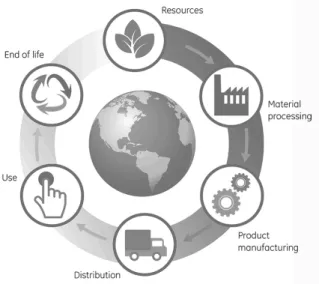
According to Dixit et al (2012) “buildings, building materials and components consume nearly 40 percent of global energy annually in their life cycle stages, such as production and procurement of building materials, construction, use and demolition.” Hence, to achieve a better understanding of energy in buildings it is important to distinguish and quantify the energy requirements in each phase of the life cycle.
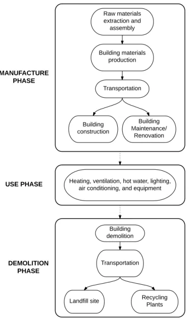
The system boundaries of a LCEA analysis include the energy use on the following phases:
1. Manufacture; 2. Use;
3. Demolition.
Manufacture Phase
The first phase of buildings energy life cycle, the manufacture phase, accounts for the energy consumption required for the following unit processes:
• Raw material extraction and assembly;
• Raw materials transportation until the factory;
• Building materials production;
In addition, the manufacture phase also accounts for the energy consumption associated with buildings construction process, as well the activities required for buildings maintenance/renovation.
The manufacture phase corresponds to all the energy consumed for buildings production and maintenance.
Use Phase
The second phase of buildings energy life cycle is the use phase. The energy consumption for this phase includes the activities necessary to keep the indoor environment such as, heating, ventilation and hair conditioning (HVAC), and electrical appliances.
The use phase corresponds to all the energy required to maintain buildings operating.
Demolition Phase
The last phase of a building energy life cycle is the demolition phase. The unit processes associated to this phase are:
• Building demolition;
• Transportation of construction waste to landfill sites.
2.3.1 Identifying Life Cycle Energy (LCE) Requirements
Embodied Energy (EE)
Embodied energy is defined as the energy required for building’s material production, across the supply chain, and for building construction. In other words, it is the energy present in the building materials as well as the energy required to construct and to maintain buildings.
Embodied energy can be divided in two parcels:
Raw materials extraction and
assembly
Building materials production
Transportation
Building construction
Building Maintenance/
Renovation
Heating, ventilation, hot water, lighting, air conditioning, and equipment
Building demolition
Transportation
Landfill site Recycling
Plants
MANUFACTURE PHASE
USE PHASE
DEMOLITION PHASE
1. Initial embodied energy; 2. Recurring embodied energy.
Initial embodied energy
The first parcel, initial embodied energy, corresponds to the energy required for extraction, manufacturing and transportation of building materials, and it is also the energy necessary for the entire construction process. It can be expressed as (Ramesh, Prakash, & Shukla, 2010):
𝐸𝐸!= 𝐸! + 𝐸! (2.1)
Where,
EEi – Initial embodied energy of the building; EEM –Energy for building material manufacturing: Ec– Energy used for building construction.
The energy component for the product stage can be calculated by the following expression (Ramesh, Prakash, & Shukla, 2010):
𝐸! = 𝑚!𝑀! (2.2)
Where,
EM– Energy required for material manufacturing;
mi – Quantity of building material required to produce a building; Mi – Energy content of material per unit quantity.
The energy for building construction stage is the sum of the energy required to transport building materials to the building yard and the energy consumption of the equipment during the construction works. It can be expressed by (Hong, Ji, Jang, & Park, 2014):
𝐸! = 𝐸!_!+ 𝐸!_! (2.3)
Where,
EC – Energy required for building construction;
The energy component for the transportation is defined as (Hong, Ji, Jang, & Park, 2014):
𝐸!_! =2 . 𝑇𝐷! !
.𝑄!.𝐸𝐶 !
!
!
!!!
!
!!! (2.4)
Where,
EC_T– Energy consumption from material transportation;
𝑇𝐷!!– Transportation distance of the building material i from the plant to the construction site using vehicle j;
Qi – quantity of material i;
𝐸𝐶!! – Energy consumption per kilometer of vehicle j for a ton or cubic meter of material i.
The energy component for the on-site construction equipment is defined as (Hong, Ji, Jang, & Park, 2014):
𝐸!_!= 𝐷!
! !
!!! !
!!!
.𝐸𝐶!!
(2.5)
Where,
EC_E– Energy consumption from on-site construction equipment;
𝐷! !
- Duration of equipment k usage;
𝐸𝐶!! - Energy consumption per hour of equipment k.
The duration of equipment usage, 𝐷! !
, is calculated by the following formula (Hong, Ji, Jang, &
Park, 2014):
𝐷!
!
=𝑄! 𝐶
!
! (2.6)
Where,
𝐷!
!
- Duration of equipment k usage;
𝑄! –Quantity of material i;
Recurring embodied energy
The second parcel, recurring embodied energy, is the energy used for maintenance and renovation activities that are related to replacement of building materials after buildings’ construction. This energy can be expressed as (Ramesh, Prakash, & Shukla, 2010):
𝐸𝐸!= 𝑚!𝑀! 𝐿!/𝐿!! −1
(2.7)
Where,
EEr – Recurring embodied energy of the building;
mi – Quantity of building material required to produce a building; Mi – Energy content of material per unit quantity;
Lb – Life span of the building;
Lmi– Life span of the building material.
The total embodied energy consumption is the sum of initial and recurring embodied energy, and may be expressed as (Ramesh, Prakash, & Shukla, 2010):
𝐸𝐸= 𝐸𝐸!+𝐸𝐸! (2.8)
Where,
EE – Embodied energy of the building; EEi – Initial embodied energy of the building; EEr – Recurring embodied energy of the building.
Operational Energy (OE)
Operational energy is the energy used to maintain the comfort conditions inside buildings through processes such as heating, cooling, ventilation, lightning, hot water and appliances and equipment operation. Operational energy may be expressed as (Ramesh, Prakash, & Shukla, 2010):
Where,
OE – Operating energy of the building; EOA – annual operating energy; Lb – Life span of the building.
Demolition Energy (DE)
Demolition energy is defined as the energy required to demolishing and transporting the waste materials to landfill sites or recycling plants. This energy is associated to the end of the building life cycle. It can be expressed as (Ramesh, Prakash, & Shukla, 2010):
𝐷𝐸= 𝐸!+𝐸! (2.10)
Where,
DE – Demolition energy of the building; ED – Energy for destruction of the building; ET – Energy for transportation of waste material.
Life Cycle Energy (LCE)
The total energy in buildings’ life cycle can be defined as the sum of the three parcels mentioned above. It is expressed as (Ramesh, Prakash, & Shukla, 2010):
𝐿𝐶𝐸=𝐸𝐸+𝑂𝐸+𝐷𝐸 (2.11)
Where,
LCE – Life cycle energy of the building; EE – Embodied energy of the building; OE – Operating energy of the building; DE – Demolition energy of the building.
2.3.2 Embodied Energy (EE) vs Operational Energy (OE)
Previous studies and investigation make possible to assert that operational energy is by far the largest contributor to the total energy consumption in buildings’ life cycle. It can account approximately 80% of the total energy consumption in a buildings life cycle (Ramesh, Prakash, & Shukla, 2010). For that reason, during the last decades, studies have been focusing on reducing operational energy, while embodied energy and demolition energy received less attention. In fact, demolition energy can be despised, since it only represents 1% of the building’s total life cycle energy (Aye, Ngo, Crawford, Gammampila, & Mendis, 2012). However embodied energy may no longer continue to be ignored. Recent research has indicated that embodied energy could reach approximately 40% of the total energy used during the lifetime of the building (Huberman & Pearlmutter, 2008).
According to many authors, there is a cause-effect relationship between operating and embodied energy, which means that a decrease in operational energy efficiency is going to lead to an increase in embodied energy. For example, a reduction in operating energy can be considerably decreased by improving the insulation of the building envelope or technical solutions. However, the embodied energy will increase, due to energy intensive materials used in the energy saving measures (Thormark, 2002) (Ramesh, Prakash, & Shukla, 2010). Sartori and Hestnes found out a lineal relation between operating and total energy, as it possible to observe in the figure 2.3.2.1.
Once significant efforts were made so far to reduce operational energy, embodied energy becomes more important to minimize in buildings overall consumption.
Although operational energy is by far the major contributor in the life cycle energy (LCE), embodied energy is increasingly prominent and cannot be overlooked.
2.3.3 Problem Statement
The construction sector has a large potential to increase energy conservation. Applicable efforts were made in order to reduce operational energy, through use of passive and active technologies, high-performance design, construction and equipment. However, much more emphasis was placed into research of the operating energy domain, which leads to a lack of knowledge in what concerns the embodied energy topic. The reasons for that could be due to the following facts:
• Operational energy is still the largest energy consumer in LCE;
• It is easier to define operational energy, since the determination of embodied energy is complex and requires more time;
• In comparison to other goods, assess energy in a building is harder, since buildings are part of a complex and dynamic process, due to the variety of materials used in the construction that provides unique feature for each building (Scheur, Keoleian, & Peter, 2003)
As mentioned above, a crescent improvement in operational energy leads to a considerable increase in embodied energy. Therefore, the target in future search should focus on the problematic of embodied energy, in order to achieve sustainable construction.
Thereby, instead of studying individually the embodied energy in materials used for structural systems, it would be interesting to study the embodied energy in entire structural systems. In consequence, it was possible to define and specify the general research topic of this study: initial embodied energy in building structures. It was considered interesting to compare initial embodied energy in the same building structure, by varying the span and the material type. The building materials chosen for the building structure are concrete, steel and timber.
Figure 2.4.3.1 – Concrete structural frame (Shay Murtagh, 2015)
Figure 2.3.3.2 – Timber structural frame (Vision Development, 2015)
3. The Manufacture Phase of Structural Building Materials
In the previous chapter was defined the research area of this study. The theoretical foundations
presented so far are not enough to provide an overall comprehension of initial embodied energy in
building structures. Therefore, this chapter describes (from a LCEA perspective) the manufacture phase
of the three building materials used in the empirical part of this research: concrete, steel and timber. It
was considered fundamental to study the energy processes involved during the fabrication,
transportation, and construction of structural materials to understand embodied energy consumption in
building structures.
3.1 Introduction
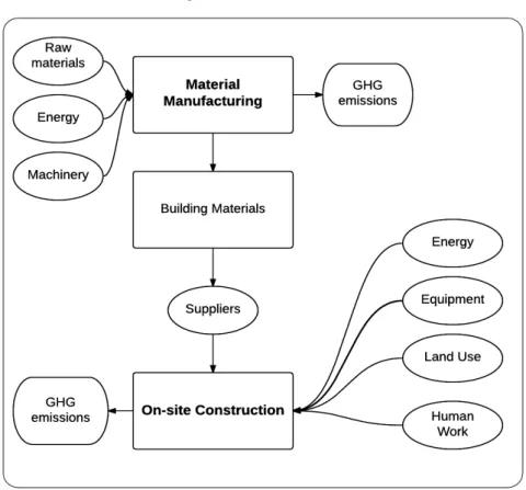
In life cycle assessments industrial-environmental systems are presented as a connection of processes with inputs and outputs, in a larger environment system (Srinivasan, Ingwersen, Trucco, Ries, & Campbell, 2014). In the building sector, the interaction between different materials and energy to gather and assemble building materials and the construction works constitute the building manufacture phase.
In figure 3.1.1 it is illustrated the general process and material inflows involved in the manufacture phase of a building.
The manufacture phase of building starts with extraction and assembly of raw materials. After raw materials are assembled, they are transported to the respective factories, where the different raw materials are combined to produce building materials. Then, the suppliers transport the building materials to the building yard. At the construction site, besides building materials, is also required other inputs such as equipment, human work, land use, and energy, in order to produce the final building.
During buildings’ manufacture phase, embodied energy is released through three different stages:
1. Product stage; 2. Construction stage; 3. Maintenance stage.
The first two stages, product and construction stage, correspond to initial embodied energy parcel, whereas the third stage, maintenance stage, corresponds to recurring embodied energy parcel.
Embodied energy consumption in buildings is difficult to assess and quantify because it is influenced by materials type, energy sources needed for the manufacture process, and construction practices (Ramesh, Prakash, & Shukla, 2010). Although, it is known that the
Product Stage Raw material extraction productionMaterial
Initial Embodied
Energy
Recurring Embodied Energy
Manufacture Phase - Embodied Energy
Transportation
Construction Stage
Maintenance Stage
Construction activities
Maintenance and renovation activities
largest embodied energy consumption is driven by the material production and its respective transportation (Cole R. , 1999).
The importance of the manufacture phase is expected to increase in the near future, since there are already several improvements to reduce operational energy, as explained in the previous chapter. Construction materials may have the promising potential to reduce the energy consumption in buildings’ life cycle, especially the structural ones. According to numerous authors, structural materials are responsible for the major consumption of embedded energy. For example, Cole et al (1996) research compared different building components (envelope, structure and services) and concluded that “the biggest part of the building’s initial (non-renewable) embodied energy is taken from the main structure of the building and it takes up to 74% of the total initial embodied energy” (Cole & Kernana, 1996).
In order to comprehend embodied energy in structural systems it is fundamental to study the manufacture and construction processes. In this research the focus will be placed only in initial embodied energy and recurring embodied energy will not be considered in this research.
In the next sub-chapters a shortly description about concrete, steel and timber production stages and the construction stage is going to be carried out.
3.2 The Product Stage
Manufacturing is imperative for world’s economy. It provides goods necessary for industries in the entire world and is also responsible for a significant part of the employment. Manufacturing activities consume a large amount of renewable and non-renewable materials and energy. In fact, the manufacture sector is the main responsible for industrial energy consumption. Every product requires energy to be produced. In consequence, more energy is consumed and more CO2 emissions are released into atmosphere. And the building industry is no exception to this. According to Ding et al (2004) “the production of building components off-site accounts for 75 % of the total energy embedded in buildings”. This highlights the importance to achieve sustainable manufacturing and improving energy efficiency of products and processes. And as it was mentioned above, the major embodied energy consumption is present in the product stage, namely in the material production, that accounts for the majority of total embodied energy (Scheur, Keoleian, & Peter, 2003).
3.2.1 Concrete raw material extraction and production
This sub-chapter is mainly based on the following literature review: (PCA, 2015) and (CIMPOR, 2015).
Concrete is an artificial building material created by the combination of aggregates with binder, water, and some chemical additives in different proportions. The high compressive strength and durability, versatility, good thermal mass, long durability and low maintenance make concrete the most used world’s building material (Habert, d'Espinose de Lacaillerie, & Roussel, 2011).
In order to study embodied energy in concrete it is necessary to have a comprehensive knowledge of the processes involved in its manufacture.
Aggregates
Aggregates constitute approximately 80% of a unit of concrete and provide strength to overall composite. The most common aggregates used are sand, gravel and stone. The aggregates used to produce concrete arrive into cement factories by lorries and are stored in appropriate locations, according to their typology and grain size. From the storage locations the aggregates are forwarded to the weighing system. After that, they are discharged into a batching plant, where the mixture with the other components will be performed.
Binders
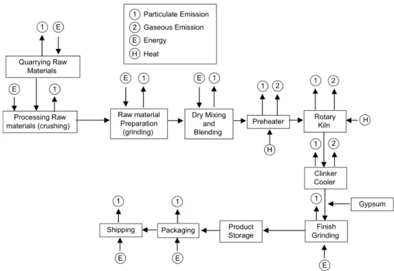
Ordinary Portland Cement (OPC) is the most common binder used to produce concrete and consume approximately 50% of the embodied energy (Goggins, Keane, & Kelly, 2010), which makes the OPC manufacturing the most energy and emission intensive process in concrete production. In fact, 5% of the world’s CO2 emissions are due to the cement industry (Huntzinger & Eatmon, 2009). According to Huntzinger et al (2009) “the calcination process (driving off CO2 from CaCO3 to form CaO) accounts for roughly half of the CO2 emitted, while
the remaining carbon results from energy usage during the production process”. For this reason, more emphasis is going to be placed into the description of cement manufacture.
(2000oC) and all the ingredients are heated. The finely ground raw material is fed into the higher end. At the lower end is a roaring blast of flame, produced by precisely controlled
burning of powdered coal, oil, alternative fuels, or gas under forced draft. As the material
moves through the kiln, certain elements are driven off in the form of gases. The remaining
elements unite to form a new substance called clinker (1400oC). Clinker comes out of the kiln
as grey balls, about the size of marbles. Then clinker is discharged red-hot from the lower end
of the kiln and generally is brought down to handling temperature in various types of coolers.
The heated air from the coolers is returned to the kilns. After the clinker is cooled, cement
plants grind and mix it with small amounts of gypsum to regulate the setting time. The end
product is very fine-grained mixture. The cement is stored in silos and is ready to be
transported and used to make concrete.
In figure 3.2.1.1 it is presented a flow diagram of general cement manufacturing process, with the different inputs and emissions during the production process.
To manufacture concrete, the production of cement alone involves a huge consumption of raw material, energy and heat and releases an important amount of solid waste materials and gaseous emissions. The manufacturing process is complex, as it was explained above, and requires a considerable number of different materials, techniques and the use of fuel resources, such as coal, oil, natural gas and petroleum coke (Huntzinger & Eatmon, 2009).
Water
The quality of water used in concrete production is essential. The use of impure water during the setting can affect the strength of concrete and cause corrosion in case of reinforcement.
During the hydration process, the combination of water with cement forms a binder. Through this process chemical reactions occur and, as the reactions proceed, there is a bonding with sand and gravel particles, which forms a solid mass.
The impact of water is low in what concerns CO2 emissions during concrete manufacturing (Goggins, Keane, & Kelly, 2010).
Admixtures
Admixtures are chemicals added to concrete to provide it certain characteristics. Successful use of admixtures depends on the use of appropriate methods of batching and concreting.
Certain admixtures, such as pigments, expansive agents, and pumping aids are used in very
small amounts during mixing.
The effectiveness of an admixture depends on several factors including: type and amount of
cement, water content, mixing time, slump, and temperatures of the concrete and air.
The energy consumption of admixtures is difficult to quantify, because of the nature of their
production. Since they account for such a small part of a unit of concrete their contribution
can be despised.
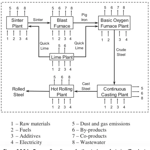
3.2.2 Steel raw material extraction and production
This sub-chapter is mainly based on the following literature review: (TATA, 2015)
Steel is the most important metal in modern society, with an annual global production of over 700 million tonnes. The low price and high strength make steel a material used in structures of buildings. The iron and steel industries are very energy-intensive; the production of steel releases a significant amount of greenhouse gas (GHG) emissions and consumes large quantities of raw materials (Burchart-Korol, 2013) (Spengler, Geldermann, Hahre, Sieverdinbeck, & Rentz, 1998).
Since hot rolled steel is much more used in construction than cold rolled steel, only the manufacturing of hot rolled steel is going to be described.
Iron making
The raw materials necessary to produce iron, sinter, iron ore and coke are extracted and placed into the blast furnace, where they are fled into the top of the furnace with limestone. The temperature inside the furnace rises around 2200ºC to reduce and melt the iron ore and the sinter. Then, is formed a pool of molten iron designated for cast iron. Although, some carbon and some impurities remain so they must be reduced by refinement, before the material becomes steel. The amount of carbon content of steel is crucial to provide strength to steel.
Refining iron into steel
Basic oxygen steelmaking (BOS) is the main bulk production process to transform iron to steel. The BOS process starts with the deposit of the hot metal (that has been previously pre-treated to remove undesirable elements) into the vessel. After that, a water-cooled lance is lowered into the vessel and oxygen is blown through the surface of the hot metal. At this stage the steel obtained is designated by crude steel.
Continuing with the refining process, the crude steel is teemed through a gas tight refractory tube into the tundish. Tundish it is a reservoir that allows the steel to flow at a controlled rate through further gas tight refractory tubes and into a series of water-cooled copper moulds. With only the outer shell solidified, the steel is drawn from the bottom of the mold through a curved arrangement of support rolls and water sprays.
Shaping steel
To shape steel is used hot rolling technique. Steel is squeezed between rolls until the final thickness and shape are achieved. The rolls exert forces of more than ten millions of newtons. The rolled steel is then cooled and prepared for further processing or is then ready to be dispatched.
The manufacture phase of steel that consumes more energy is the blast furnace. About 69% of energy is consumed due to the chemical reactions between coke and iron oxide (Michaelis, Jackson, & Clift, 1997).
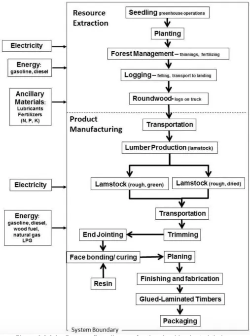
3.2.3 Timber raw material extraction and production
Timber it is produce by natural processes in the forest ecosystems and it is one of the most sustainable resources available. It is an organic material, a natural composite of cellulose fibres, and has specific physical and mechanical properties in the longitudinal, radial and tangential directions, according to the type of tree. It has been used for years as a primary source of material and energy in human society and it is the oldest material used in the construction sector. Due to a high strength ratio, timber can transfer tension and compression forces. Is used for a range of structural forms such as beams, columns, trusses and girders. It is also used in building systems as deck members and in formwork of concrete. Timber structures are resistant, and the proof of that are the historical buildings spread all over the world (Porteous & Kermani, 2007).
Wood materials have the great potential to reduce GHG, since they can storage carbon from atmosphere, and create a major role in the sustainable development of the building industry (Sathre, 2014).
In general, the life cycle of timber building materials begins with the growth of trees, followed by the harvest and processing of woody biomass, the manufacture and assembly of wood based products, the utilization and maintenance of buildings, ending with the disassembly and management (Sathre, 2014).
However, depending on the product purpose the manufacture process differs. Since it is intended to assess the structural materials, the focus of this research is going to be on the manufacture process of glued-laminated timber, also known as glulam. Glued-laminated timber is one of the oldest engineered wood products. It is a structural material prepared from selected pieces of wood, and can have a straight or curve form. It may be used as beams and columns in residential and commercial dwellings, such as church arches, warehouse roof beams and as purlin. It is produced from small sections of timber boards, designated by laminates, which are glued together with the grain of all layers parallel to the longitudinal axis. The lumber used in the glued-laminated timber production is produced from the softwood process, and it is a special lumber used in the construction of laminated timber and it is known as lamstock (Puettmann, Oneil, & Johnson, 2013).
The manufacture of glulam starts with extraction of wood in the forest, through forestry operations, that include site preparation, planting, fertilization and final harvest. During this process, different levels of energy are used to extract wood. After the extraction the logs are carried to lumber mills by lories.
The manufacturing process of glued laminated timber can be divided in four parts:
1. Drying and grading lumber;
2. End jointing the lumber into longer laminations; 3. Face bonding the lamination;
4. Finishing and fabrication.
are made, holes are drilled, connectors are added and a finish is applied. (Puettmann, Oneil, & Johnson, 2013).
In the figure 3.2.3.1 it is possible to observe the different inputs and outputs necessary to produce the glued-laminated timber.
During the manufacturing phase of glulam, the quantity of GHG emissions released into the atmosphere is very low.
3.3 The Construction Stage
On-site construction activities are responsible for significant environmental impacts, such as greenhouse emissions, land use and solid and liquid waste, and also for energy consumption.
It is estimated that in Europe and in the United States energy consumption in the construction stage can reach between 7 a 10% of the total embodied energy (Cole R. , 1999). In fact, embodied energy related with construction only account for a minor part of the total life cycle energy demand (Gustavsson, Joelsson, & Sathre, 2010), and few studies have quantified the energy consumption in the construction stage (Hong, Ji, Jang, & Park, 2014). However, to make a correct initial embodied energy analysis, it is fundamental to quantify embodied energy consumption for construction activities.
The construction process and efficiency of the equipment’s adopted can have significant impacts in the construction costs and construction delays (Cole R. , 2000). So it is fundamental to choose good construction practices in the design phase of buildings, which can also be achieved by assessing the embodied energy in the construction stage.
The construction process for structural assemblies cover the activities related with the erection of the building structural system. The construction process can be different from structural system to structural system, but in general the main processes and on-site activities are common to the three structural materials used in this research: concrete, steel and timber.
The energy consumption in the construction stage is directly related to:
1. Transportation of building materials; 2. On-site construction equipment.
3.3.1 Transportation
The energy consumption during building materials transportation is related to:
• The distance travelled from the distribution centres to the building yard;
• Fuel type and efficiency;
• Vehicle type and size;
• Weight of vehicle and building material to transport.