FACULDADE DE CIÊNCIAS
DEPARTAMENTO DE ENGENHARIA GEOGRÁFICA, GEOFÍSICA E ENERGIA
Dynamic Insulation as a strategy for Net-Zero Energy Buildings
João Tiago Lopes Alves Homem
Mestrado Integrado em Engenharia da Energia e do Ambiente
Dissertação orientada por:
Prof. Doutora Laura Aelenei (FCUL)
Roel Loonen (TU Eindhoven)
Atualmente, o consumo de energia nos edifícios representa cerca de 40% da necessidade total de energia primária na União Europeia (UE), assim como cerca de 36% das emissões de gases com efeito de estufa (GEE). Desta forma, “o setor dos edifícios” tem um potencial significativo em matéria de poupança de energia, e para o que isso pode representar em termos de redução de GEE, não só na construção de novos edifícios, mas também na renovação dos existentes. A sua importância é, por isso, fulcral para se atingir as metas 20-20-20 do Roadmap 2050 da UE. Como tal, a regulamentação lançada pela UE ao nível do desempenho energético dos edifícios tem vindo a incorporar um novo conceito: o de edifícios de balanço energético nulo ou quase nulo (nZEB ou NZEB). Este conceito baseia-se na cobertura do consumo de energia do edifício através de fontes de energia renovável, de produção local ou nas proximidades (nearby). No entanto, o primeiro passo para se atingir o objetivo pretendido consiste na implementação de medidas de eficiência energética que permitam reduzir as necessidades energéticas do edifício para um valor mínimo economicamente viável a ser colmatado por recurso a fontes de energia renovável.
Ao nível da envolvente dos edifícios, o foco da legislação da UE consiste em atingir níveis de maior isolamento térmico e maior estanquicidade para reduzir o consumo de energético. Embora o aumento do nível de isolamento térmico contribua para diminuir as perdas de calor através das fachadas dos edifícios no Inverno, no Verão poderá ser desadequado pois restringirá o fluxo de calor quando se pretende extrair os ganhos de calor indesejados. Deste modo, os edifícios com isolamento térmico elevado têm um maior risco de sofrerem problemas de sobreaquecimento, uma vez que a temperatura interna responde mais rapidamente ao aumento dos ganhos solares e internos. Uma solução para esse problema poderá passar pela utilização de elementos de fachada com um coeficiente de transmissão térmica (U) variável, o que, por exemplo, permitiria “desligar/desconectar” o isolamento térmico durante a noite no Verão.
A existência de um U variável, permitiria fazer uma gestão das trocas térmicas entre os ambientes interior e exterior de acordo com as temperaturas registadas. Para atingir esse fim, a aplicação de elementos ou sistemas de isolamento dinâmico/adaptativo aparece como uma possibilidade interessante. Estas soluções são alternativas ao convencional procedimento de aumentar a espessura de isolamento térmico para evitar as perdas térmicas, uma vez que apresentam um comportamento dinâmico permitindo uma maior flexibilidade térmica e energética dos edifícios. Em comparação com o isolamento “estático”, os elementos de isolamento dinâmico podem exibir parâmetros térmicos variáveis, como condutividade térmica e emissividade. Estes permitem que as fachadas dos edifícios sejam elementos responsivos em relação ao ambiente térmico exterior.
Neste projeto, o objetivo principal foi o estudo do potencial da aplicação de elementos ou sistemas de isolamento dinâmico ao nível dos edifícios. Para tal, o projeto foi estruturado em várias etapas.
O primeiro passo passou por fazer uma revisão bibliográfica dos elementos e sistemas que apresentassem um comportamento térmico dinâmico e que pudessem ser utilizados ao nível dos edifícios desempenhando a função de isolamento térmico. Após feita essa identificação, os elementos mais relevantes foram descritos e classificados de acordo com o mecanismo utilizado para obter um comportamento dinâmico (processos de transferência de calor: condução ou convecção) e a sua escala de atuação (macro, micro ou nano). Seguidamente, o próximo passo foi determinar como efetuar a simulação computacional do desempenho térmico dos elementos de isolamento dinâmico. Ao nível da simulação de parâmetros que variem ao longo
do tempo, verificou-se que os vários tipos de software existentes apresentam bastantes limitações, uma vez que quando foram concebidos a dinamicidade das propriedades dos materiais não era uma questão central. Para fazer esse tipo de análise, concluiu-se que o EnergyPlus era o software mais adequado por apresentar maiores capacidades para a modelação de fachadas adaptativas.
Para prever o desempenho de elementos de isolamento dinâmico, no EnergyPlus, podem ser utilizadas duas abordagens: a ClassList MovableInsulation e o grupo EnergyManagementSystem (EMS). Na primeira, a resistência térmica do elemento de isolamento é determinada em função de horários (schedules) que reproduzem a alteração da mesma em diferentes condições ao longo do tempo, sendo esta realizada num regime de post-processing. A segunda abordagem permite definir o comportamento de um dado elemento de isolamento dinâmico, ao longo da simulação, de acordo com determinados parâmetros físicos definidos como sensores (ex.: temperatura exterior, radiação incidente numa fachada, temperatura interior)
Após serem detalhadas as abordagens existentes no EnergyPlus que podem ser utilizadas para simular estes elementos de isolamento dinâmico, foi feita uma análise comparativa de modo a concluir qual a abordagem que mais se adequa ao objetivo pretendido. Embora o EMS seja mais realista, uma vez que permite fazer um controlo ao longo da simulação, apresenta algumas limitações que fazem com que não seja possível a substituição das construções. Deste modo, a abordagem utilizada para efetuar o caso de estudo foi a
ClassList MovableInsulation.
Aplicando a abordagem atrás mencionada, foi desenvolvido um caso de estudo representando um modelo ilustrativo de uma moradia localizada em Lisboa, Portugal. A análise realizada focou-se no período de Verão (estação de arrefecimento) durante o qual se estudou o efeito da aplicação de uma layer de isolamento exterior removível (movable insulation), de 10 cm de poliestireno expandido (EPS), na redução do sobreaquecimento no interior da moradia (quando a temperatura média do ar é superior a 25°C). Com uma estratégia de controlo adequada, verificou-se uma redução, face ao cenário base, de 51% nas horas de sobreaquecimento e de 35% no consumo de energia elétrica para arrefecimento.
Finalmente, foi feita uma análise comparativa entre a solução anterior e a aplicação de um sistema de ventilação natural com uma taxa de ventilação de 5 renovações por hora. Para esse ultimo cenário, verificou-se uma redução significativamente maior, face ao cenário baverificou-se, tanto no consumo de arrefecimento (cerca de menos 67%) bem como nas horas de sobreaquecimento (68% menos). A utilização conjunta da movable
insulation e da ventilação natural permitiu uma redução de 72% no consumo de energia para arrefecimento
e de cerca de 80% nas horas com temperaturas interiores superiores a 25°C.
Palavras-chave: Isolamento Dinâmico, Edifícios de Balanço Energético Nulo, EnergyPlus, Movable
The current focus when it comes to size thermal insulation systems is to reach the highest insulation level. Besides the fact that the goal of this approach is to reduce the heat losses, especially during the winter, this can bring severe overheating problems that need to be solved. This way, dynamic insulation elements appear as a possible solution to this problem as they allow to have an adaptive range of their thermophysical properties, such as thermal conductivity, instead of a static value registered on the conventional insulation systems. There are several different materials and systems, with different mechanisms of control and resultant adaptive ranges, that can be used as dynamic insulation elements. Nowadays, in terms of simulation framework, the most suitable software to predict the performance of dynamic insulation elements is EnergyPlus, which offers two approaches to do it: the Movable Insulation Actuator and the Surface Construction State Actuator (on the Energy Management System group). After doing a comparison between these two approaches, it was concluded that the second one is the most promising, but due to limitations regarding implementation details, it was not used for the case-study analysis. By using the MovableInsulation Actuator in the case study analysis, for the climate of Lisbon, Portugal, it was concluded that the application of a removable insulation layer (10 cm of EPS), with an optimized control strategy, achieved 51% decrease on overheating hours and 35% of decrease on the cooling energy demand, in comparison with a base case. Moreover, the use of movable insulation in combination with a system of natural ventilation can allow greater savings in terms of cooling and a more significant reduction on the overheating hours.
Although some of the details of how to assess the dynamic insulation elements become clearer throughout this analysis, there is much more work and research that needs to be done to accelerate the product development and technology implementation of these systems.
Keywords: Dynamic Insulation, Net-Zero Energy Buildings, EnergyPlus, Movable Insulation, Energy
Contents
Resumo ... iii Abstract ... v List of Figures ... ix List of Tables ... x List of Appendices ... xi Acknowledgements ... xiiiAbbreviations and Symbols ... xv
Chapter 1 – Introduction ... 1
1.1 – Context about Net-Zero Energy Buildings ... 1
1.2 – Motivation for the application of Dynamic Insulation ... 2
1.3 – Role of the BPS tools ... 2
1.4 – Research goals ... 3
1.5 – Structure of the thesis ... 3
Chapter 2 – State-of-the-art overview ... 5
2.1 – Background ... 5
2.2 – Dynamic Insulation Solutions ... 6
2.2.1 - Macro-scale actuation ... 6
2.2.1.1 – Systems based on heat convection through air to control the heat transfer ... 6
2.2.1.2 – Systems based on heat convection through a working liquid to control the heat transfer . 8 2.2.1.3 – Active Insulation System ... 10
2.2.2 – Micro/Nano-scale actuation ... 11
2.2.2.1 – Systems based on varying the pressure of a certain gas to control conduction... 11
2.2.2.2 – Systems based on varying the gas-surface interaction in an insulation panel ... 12
2.2.3 – Movable Insulation System: Thermocollect ... 14
2.2.4 - Comparison ... 15
Chapter 3 – Simulation approaches for performance prediction of dynamic insulation elements ... 17
3.1 - Background ... 17
3.2 – Tools available in EnergyPlus... 17
3.2.1 – SurfaceControl: MovableInsulation Class List ... 18
Dynamic Insulation as a strategy for Net-Zero Energy Buildings
viii João Tiago Lopes Alves Homem
3.2.2 – Surface Construction State Actuator on EMS ... 19
3.2.2.1 – Brief description ... 19
3.2.2.2 – Implementation details ... 21
3.2.3 – Preliminary results ... 22
3.2.3.1 – MovableInsulation Actuator... 22
3.2.3.2 – Surface Construction State Actuator ... 24
3.2.4 – Critical comparison ... 25
Chapter 4 – Case study analysis ... 27
4.1 - Introduction ... 27
4.2 – Building model description ... 27
4.2.1 – Building geometry and construction details ... 27
4.2.2 – Internal loads: lighting, people and equipment ... 28
4.2.3 – HVAC System ... 29
4.3 – Overheating problem analysis and respective control strategy ... 30
4.3.1 – Problem description ... 30
4.3.2 – Control strategy ... 30
Chapter 5 – Results ... 31
5.1 – Introduction ... 31
5.2 – Base case ... 32
5.3 – Optimization of the control strategy: Movable Insulation case ... 33
5.4 – Natural ventilation case vs Movable insulation case ... 35
5.5 – Combination of movable insulation and natural ventilation ... 37
Chapter 6 – Conclusions and future work ... 39
References ... 41
List of Figures
Figure 1.1 – The path toward a Net-Zero Energy Building: first follow the efficiency path and then cover
the remaining energy demand by installing renewable energy sources [3] ... 1
Figure 1.2 – Illustration of dynamic energy flows and interactions in buildings with adaptive facades (from: IEA EBC Annex 44, adapted by Fernández Solla [47]) ... 2
Figure 2.1 – Permeodynamic (left) and parietodynamic (right) insulation sketches [17] ... 7
Figure 2.2 – Dynamicity of the U-value according the air flow velocity through a breathing wall [21] ... 7
Figure 2.3 – FESU in the insulating state (left) and also on conducting state (right) [7] ... 8
Figure 2.4 – Variation of the U-value in both insulating and conducting state depending on the indoor-outdoor temperature difference [7] ... 8
Figure 2.5 – Outline of the system [48] ... 9
Figure 2.6 – Conceptual design of a bi-directional thermodiode. Forward (1) or backwards (2) heat flow direction modes can be reversibly changed via rotable joints. A top view of the system (3) is also shown [24] ... 9
Figure 2.7 – Basic sketch of the smart thermal insulation system (1), in the insulating mode (2) and in the conduction mode (3). Change between modes is achieved via a movable partition on the slab wall [27] . 10 Figure 2.8 – Principle of functioning of Active Insulation [28] ... 10
Figure 2.9 – Variation of the thermal conductance through the 20 mm thickness of a VCI panel as a function of the internal hydrogen pressure [31] ... 11
Figure 2.10 – Principle of functioning (on the left) (adapted from Burdajewicz, Korjenic, & Bednar, 2011) and range of variation of the thermal conductivity (on the right) [49] ... 12
Figure 2.11 – Schematic of the equipment for the measurements (on the left). Variation of the apparent thermal conductivity with the increase of air pressure for both materials (on the right) [9] ... 12
Figure 2.12 – Illustration of adaptive multilayer wall: (a) is the insulated state, with N layers of air and its equivalent thermal resistance network is presented below (b); (c) is the configuration for collapsed wall or conductive state whereas (d) is its equivalent thermal resistance [34] ... 13
Figure 2.13 – Study of the variation of the thermal conductivity in regard with different nanotube orientations [36] ... 13
Figure 2.14 – Illustration of the way of functioning of the Thermocollect system [37] . In this system, the exterior movable panels can be either closed (1) or open (2). The goal is to modulate the thermal mass of the wall, as desirable throughout the day (3). ... 14
Figure 3.1 – Display of some of the class lists, in IDF Editor, that the user can edit before running his simulation in EnergyPlus. ... 17
Figure 3.2 – Sketch of the different approaches used in EnergyPlus to model dynamic insulation elements, seen in terms of thermal resistances. The green resistances symbolize the ones being added and the red the ones being removed or having their properties changed. ... 18
Figure 3.3 – Example of an application of the Class List SurfaceControl: MovableInsulation on IDF Editor. In this case, exterior movable insulation, in all surfaces of the building (S, N, W, E) is controlled according to a specific Summer Control schedule. ... 19
Figure 3.4 – Class Lists available on the Group Energy Management System (EMS) ... 20
Figure 3.5 – Schematic that presents the main components of an Energy Management System (EMS) and displays the way of functioning in order to control a dynamic insulation system ... 20
Dynamic Insulation as a strategy for Net-Zero Energy Buildings
x João Tiago Lopes Alves Homem
Figure 3.6 – Example of an application of the Class List EnergyManagementSystem:Actuator which sets
each surface as Surface: Construction State Actuators ... 21
Figure 3.7 – Methodology followed for the 2nd Day OFF Scenario at the summer period. Firstly the schedule described was defined and then it was used on the SurfaceControl:MovableInsulation Class List ... 22
Figure 3.8 – Results from all the scenarios compared on the same plot for the winter period ... 23
Figure 3.9 – Results from all the scenarios compared on the same plot for the summer period ... 23
Figure 3.10 – EMS Program to change between low and high conductivity states ... 24
Figure 3.11 – Graph which illustrates the variability of the indoor temperature according to the EMS control strategy defined ... 24
Figure 3.12 – Error messages displayed after running EnergyPlus with EMS ... 25
Figure 4.1 – Case study building geometry ... 27
Figure 5.1 – Control strategy applied in EnergyPlus. First the Schedule:File class list imports the control schedule for each surface from the .csv file which will be used as input for the MovableInsulation class list ... 31
Figure 5.2 – Cooling season on the base case where the overheating problem is highlighted ... 32
Figure 5.3 – Radiation limit optimization ... 33
Figure 5.4 – Illustration of the application of the control strategy on the indoor temperature during the cooling season ... 34
Figure 5.5 – Illustration of the effect of the movable insulation during the extreme summer week in Lisbon ... 34
Figure 5.6 – Illustration of the way of functioning of the control strategy, on the North Wall, during 3 summer days in July ... 35
Figure 5.7 – Illustration of the effect of the natural ventilation on the indoor temperature during the cooling season ... 36
Figure 5.8 – Comparison between the effect of the movable insulation and the natural ventilation during the extreme summer week in Lisbon ... 36
List of Tables
Table 2.1 – Comparison between traditional and state-of-the-art insulation materials [14] ... 5Table 2.2 – Comparison of some of the dynamic insulation technologies based on the range of adaptive control available in the literature ... 15
Table 4.1 – Opaque elements for all the constructions (from outside to inside)... 28
Table 4.2 – Lighting usage profile ... 28
Table 4.3 – Occupation profile [45] ... 29
Table 5.1 - Results for different cooling capacities, before and after the application of the movable insulation ... 32
Table 5.2 – Base case results ... 32
Table 5.3 – Indoor temperature optimization ... 33
Table 5.4 – Comparison between the results of the thermal simulation on the base case and on the movable insulation case ... 34
Table 5.5 – Comparison between the results of the thermal simulation on the base case and on the natural ventilation case... 36
List of Appendices
Figure A.1 – Desired effect of the shading device during the cooling season ... 45
Figure A.2 – Angle geometry to calculate the width of the shading device ... 45
Figure A.3 – Calculation of the width of the shading device, on Wolfram Mathematica ... 45
Table A.1 – Simulation parameters... 46
Table A.2 – Sizing Period: Design Days for Lisbon [42] ... 46
Table A.3 – Monthly undisturbed ground temperature values, for 2.0 m depth, in GroundTemperature:BuildingSurface [42] ... 46
Acknowledgements
To begin with, this dissertation marks the end of a long but outstanding academic period full of rewarding experiences. All of this would not be possible without the full support of my closest family: my parents José and Cita, my sister Ana, my brother-in-law Daniel and my grandparents Ermelinda and António. Their encouragement throughout all my academic career, was of the utmost importance to surpass all the difficult moments that I found along the way.
I am truly grateful for the possibility that was given to me to develop my Master Thesis during an Erasmus internship at the Eindhoven University of Technology, in the Netherlands. Firstly, I would like to thank to Prof. Guilherme Carrilho da Graça and to my advisor from FCUL, Prof. Laura Aelenei, for all the supervision, and initial contacts needed to make this mobility possible. Secondly, I would like to thank to my TU/e advisors, Prof. Jan Hensen and Roel Loonen for all the invaluable supervision and advice. It was a pleasure to be part of the Building Physics & Services group, where I greatly improved my academic and social skills.
Moreover, I would like to thank to all the amazing friends that I met in Eindhoven who made this an unforgettable experience. A special remark for my housemates and friends Luís, Pedro, Robin, Dani and Bartosz for all the adventures and for being with me together on this MSc Thesis struggle. To my girlfriend Elisabete, the best this Erasmus experience brought me, I would like to thank for her endless support and love, which gave me all the strength to conclude my dissertation.
Finally, I want to thank all my fellow colleagues and professors that I met during my 5 years at FCUL, for all the countless social and academic experiences, which shaped me in the person that I am today.
Abbreviations and Symbols
ACH Air Changes per Hour
BESTEST Building Energy Simulation Test
BPS Building Performance Simulation
CTF Conduction Transfer Function
DOE U.S. Department of Energy
EBC Energy in Buildings and Communities Programme
EMS Energy Management Systems
ERL EnergyPlus Runtime Language
EPBD Energy Performance of Buildings Directive
EPS Expanded Polystyrene
EU European Union
FESU Facade Element with Switchable Insulation
GHG Greenhouse Gases
GIM Gas Insulation Materials
GMT Greenwich Mean Time
HVAC Heating, Ventilation and Air Conditioning
IEA International Energy Agency
LST Local Solar Time
NIM Nano Insulation Materials
nZEB Nearly-Zero Energy Building
NZEB Net-Zero Energy Building
PCM Phase Change Materials
PUR Polyurethane
Dynamic Insulation as a strategy for Net-Zero Energy Buildings
xvi João Tiago Lopes Alves Homem
TARP Thermal Analysis Research Program
VIM Vacuum Insulation Materials
VIP Vacuum Insulation Panels
VSDI Void Space Dynamic Insulation
XPS Extruded Polystyrene
Ar Argon
H2O Water
g-value Solar Heat Gain Coefficient (SHGC)
Rc-value Thermal Resistance (m2.K/W)
Rins Total Thermal Resistance in the insulating state (m2.K/W)
Rcond Total Thermal Resistance in the conducting state (m2.K/W)
Rconv Thermal Resistance regarding heat transfer by convection (m2.K/W)
Rp Thermal Resistance regarding heat transfer by conduction (m2.K/W)
Rrad Thermal Resistance regarding heat transfer by radiation (m2.K/W)
Tin Indoor Mean Air Temperature (°C)
Tout Outdoor Dry-Bulb Temperature (°C)
U-value Thermal transmittance (W/m2.K)
Greek Letters 𝛼 Solar altitude (º) δ Solar declination (º) ϕ Latitude (º) ω Hour angle (º) λ Thermal conductivity (W/m.K)
Chapter 1 – Introduction
1.1 – Context about Net-Zero Energy Buildings
Nowadays, in Europe, energy consumption in buildings accounts for around 40% of total primary energy demand and 36% of total greenhouse gases (GHG) emissions [1]. This way, the ‘buildings sector’ has been acknowledged by the European Union (EU) has having a significant potential regarding energy savings (and consequently in GHG emissions) in the construction of new buildings and in the refurbishment of existent ones. This sector is central not only to achieve the EU 20-20-20 targets but also to meet the long term goals defined in the low carbon economy roadmap 2050 [1]. Thereby, the most important action was to launch several regulations to converge the built environment to the concept of Net-Zero Energy Buildings (NZEB). The main legislative document at EU level with the goal to increase the energy efficiency in buildings is the Energy Performance of Buildings Directive – Recast (EPBD Recast, 2010/31/EU), which sets that by 31st of December 2020, all new buildings must be nearly-Zero Energy Buildings (nZEB) [2].
This NZEB concept is based on covering the energy demand through renewable energy sources (RES), produced on-site or nearby [2]. However, first it is mandatory to achieve significant savings at the consumption level, applying energy efficiency measures to reduce energy demand (Figure 1.1). This is the first, and the most important step on the path towards NZEB because it would be financially impossible to cover all the demand just by setting up a massive installed power of renewable energy sources to equal the consumption [3]. Although, there is a great need to improve buildings’ performance to meet the requirements of this directive, as a very large percentage of European buildings does not comply with it. Therefore, it is clear that further increasing the energy efficiency in the buildings’ envelope elements is of great importance to achieve the Net-Zero Energy concept and develop a whole new generation of buildings in the urban context [4].
Figure 1.1 – The path toward a Net-Zero Energy Building: first follow the efficiency path and then cover the remaining energy demand by installing renewable energy sources [3]
Dynamic Insulation as a strategy for Net-Zero Energy Buildings
2 João Tiago Lopes Alves Homem
1.2 – Motivation for the application of Dynamic Insulation
The current focus throughout EU national building regulations is on having higher thermal insulation levels and increased air tightness, in order to reduce energy consumption. [5]. Despite the fact that having a static higher insulation level will contribute to lower the heat losses from buildings in winter, it will also restrain heat flow across the wall when this is potentially beneficial. An example of that is during nighttime hours in summer, when it is useful to extract the undesired heat gains, resultant of internal loads and solar gains through the windows, that were accumulated in the building compartments during the day. Highly insulated dwellings have increased risk of experiencing severe overheating problems, as internal temperature responds more rapidly to the increase of solar and internal gains [6].
To avoid overheating, façade elements with switchable U-value could be a possible solution, which would allow to ‘switch off’ the thermal insulation during nighttime in summer [7], [8]. A low U-value would help to keep the heat loads indoors when heating is needed while a high U-value would allow cooling the building when the outdoor temperature is lower than the indoor temperature [9]. To address this, dynamic/adaptive insulation solutions are interesting alternatives to the regular one-dimensional way of only adding more insulation and improving air tightness. This concept can be applied on either opaque or translucent elements, but the focus of this study will be on the opaque façade.
The application of dynamic insulation elements fits into the concept of the responsive/adaptive building envelopes/facades, because by adjusting their thermo-optical properties, they allow to actively and selectively manage the energy and mass transfer between the building and its surrounding environment (Figure 1.2). This has been seen as a breakthrough approach, not only contributing to improve the energy flexibility of the buildings but also as a way of improving the indoor environment quality for its occupants [10].
1.3 – Role of the BPS tools
Nowadays, there is a need to assess the performance, to support and accelerate the implementation of these adaptive elements. To do so, Building Performance Simulation (BPS) tools play a major role in the process, as they allow to assess different design and control strategies that maximize building’s performance and support product development [11]. However, the application of BPS to study the performance of these
Figure 1.2 – Illustration of dynamic energy flows and interactions in buildings with adaptive facades (from: IEA EBC Annex 44, adapted by Fernández Solla [47])
elements when integrated at a building level has not been sufficiently explored to reach a point where it is possible to have a clear level of understanding about what are the most important aspects in which the simulation strategy should focus on [12]. The fact that information available on this subject is limited and dispersed, and that current simulation tools were not originally developed for this purpose states a big challenge for a successful design of adaptive facades and leaves limited guidance to the BPS users [10]. Loonen et al. (2016) identified that in comparison to conventional static facades, there are two important additional requirements when it is needed to predict the performance of adaptive façade systems: modelling the time varying façade properties and the dynamic operation of façade adaptation.
1.4 – Research goals
The main goals of this dissertation were to:
• Perform an extensive study of different insulation materials/systems which can be integrated at the building level to achieve a dynamic behavior.
• Develop a simulation strategy to predict the performance of dynamic insulation elements.
• Perform an illustrative case study to conclude about the effect of the application of dynamic insulation on the overheating problem during the cooling season.
1.5 – Structure of the thesis
This dissertation is organized as follows:• In chapter 2, a state-of-art overview is given, whereas several dynamic insulation materials/systems are described and categorized by scale and range of control
• In chapter 3, the simulation approaches available in EnergyPlus to predict the performance of dynamic insulation elements are described and compared, and some preliminary results regarding their use are presented as well.
• In chapter 4, the case study is throughly described. The details about the location, the geometry of the dwelling, the simulation input data, the overheating problem and respective control strategy are referred in detail.
• In chapter 5, the results of the case study analysis are outlined
• Finally, in chapter 6 the main conclusions of the project are outlined and the recommendations for product development and future work are given
Chapter 2 – State-of-the-art overview
2.1 – Background
Over the years, several different thermal insulation materials have been developed with the purpose of thermally isolate the inside and outside environments at the building level. The ultimate goal is to achieve significant energy savings while maintaining high levels of indoor thermal comfort. When it comes to select a certain insulation material, the focus is to achieve the highest possible thermal insulation values by picking the ones that have higher thermal resistances. This means materials with lower thermal conductivity in order to reach as low thermal transmittance (U-value) as possible on the building’s façade.
Nowadays, there are numerous static insulation materials that can be applied, from traditional/conventional to state-of-the-art (high-performance) thermal insulation whereas the latter exhibit significantly lower values of thermal conductivity. Current conventional insulation materials such as mineral wool, expanded or extruded polystyrene (EPS, XPS), cellulose, cork and polyurethane (PUR) have relatively high thermal conductivities values, ranging from 20 to 50 mW/(m.K). Although, this range can vary in regard with moisture content, mass density, temperature and possible perforation of the materials [13], [14].
To decrease the U-value of the façade without ever increasing the thickness of the insulation layer, new high-performance insulation materials have been developed, which could achieve the lowest thermal conductivity values up-to-date. Vacuum insulation panels (VIP) and aerogels, are examples of some of the solutions that can be applied currently, which can reach values of conductivity as low as 3 mW/(m.K). There are also some future materials and solutions that are being researched such as vacuum insulation materials (VIM), gas insulation materials (GIM) and nano insulation materials (NIM), with an overall thermal conductivity of less than 4 mW/(m.K).
In Table 2.1, the referred traditional and high performance insulation materials are displaced in descending order of thermal conductivity.
Table 2.1 – Comparison between traditional and state-of-the-art insulation materials [14]
Material Thermal Conductivity
Conventional Cellulose 40-50 mW/(m.K) Cork Mineral Wool 30-40 mW/(m.K) Expanded Polystyrene (EPS)
Extruded Polystyrene (XPS)
Polyurethane (PUR) 20-30 mW/(m.K)
State-of-the-art (High-performance)
Aerogels 13-14 mW/(m.K)
Vacuum Insulation Panels (VIP) 3-4 mW/(m.K) Vacuum Insulation Materials (VIM)
Gas Insulation Materials (GIM) < 4 mW/(m.K) Nano Insulation Materials (NIM)
Dynamic Insulation as a strategy for Net-Zero Energy Buildings
6 João Tiago Lopes Alves Homem
Apart from the solutions previously referred, there is also a relatively new concept that can offer thermal insulation features: phase-change materials (PCM). As the name implies, these materials change from solid state to liquid state when heated, absorbing energy (endothermic process), and from liquid to solid when the temperature drops releasing energy (exothermic process) [14]. Although they are not seen as thermal insulation materials, they can be used for interesting thermal building applications, either being used as separated components in building constructions or impregnated directly into building materials. They make use of the thermal mass to reduce fluctuations in air temperature shifting the cooling loads towards off-peak periods, offering the possibility to store both sensible and latent heat [15].
However, as introduced in chapter 1, the ideal scenario is to have thermal insulation solutions that not only are able to achieve the lowest thermal conductivity values as possible, but also provide the possibility to control it within a desirable range: thus, it would be possible to control the heat flow through the façade depending on the indoor-outdoor temperature difference [12].
2.2 – Dynamic Insulation Solutions
In comparison with the static insulation, dynamic insulation elements can exhibit changeable thermal parameters, such as thermal conductivity and emissivity. These allow buildings’ facades to be responsive elements regarding the surrounding thermal environment. In addition, Loonen et al. (2014) showed that dynamic insulation elements can also be used to achieve variable thermal storage by coupling or decoupling a storage wall from a compartment, as the dynamic insulation layer is able to change between states of low and high conductivity [16].
In this subchapter, several insulation elements are described and classified according to the mechanism used to achieve a dynamic behavior and scale of actuation. In the first place, when the main heat transfer process is convection through air or liquid, the level of actuation is at a macro-scale [12]. On the other hand, when the control is based on controlling the heat conduction by varying the pressure of a gas, changing the path of the gas molecules or its interaction with the surface of the insulation panel, the level of actuation is at a micro/nano-scale [12]. Finally, a movable insulation system is described.
2.2.1 - Macro-scale actuation
The concept of dynamic insulation is not new, with research dating back to the 1970s and several definitions available from literature. It can be used either in place or in tandem with conventional insulation [17]. Most of the macro-scale applications for dynamic insulation are achieved by incorporating in the façade a system based on heat convection either through air or liquid, to control the heat transfer [12].
2.2.1.1 – Systems based on heat convection through air to control the
heat transfer
1 - One of the generic definitions of them is given by Arquis and Langlais, who set that there are three types of generic dynamic insulation systems that can be applied in buildings: parietodynamic, permeodynamic, and thermodynamic insulation [18].
Parietodynamic insulation elements have a channel where the air flow is confined, surrounded by materials impermeable to the airflow. The cold air supplied from outside preheats, by circulating on a cavity within the wall, before entering inside the building, reusing the exhaust air from indoors as an heat exchanger [19]. This process is sketched in Figure 2.1. This is somewhat similar to a ventilated façade. An example of this
insulation solution is called Void Space Dynamic Insulation (VSDI) which can achieve a range of U-values between an average of 0.092 W/m2.K in open mode and 0.20 W/m2.K in static ‘no airflow’ mode [17].
In the case of the permeodynamic insulation (or breathing wall), there is an air porous panel that works as a cross-flow heat-exchanger, with a controllable airflow between inside and outside environments [20], [21]. The U-value is a function of the air-flow, as presented in the graph of Figure 2.2.
Finally, on the thermodynamic insulation, despite being similar to the permeodynamic, the air circulates in a closed circuit and a separate heat exchanger is necessary.
2 - Pflug et al (2014), proposed and studied a translucent dynamic insulation system denominated FESU (façade element with switchable insulation), which consists on a closed model with one or various insulation panels, where the convection is controlled [7]. This element can be in two states, insulating or conduction state (Figure 2.3).
Figure 2.1 – Permeodynamic (left) and parietodynamic (right) insulation sketches [17]
Dynamic Insulation as a strategy for Net-Zero Energy Buildings
8 João Tiago Lopes Alves Homem
When it is in insulating state, the translucent panel is at the top avoiding the convection around the panel, existing this way three insulating layers (two of air and one insulation panel). On the other hand, when the system is in conducting state, the panel is a vertical middle position and there is convection around the panel due to a driving pressure difference between the back and front, allowing the heat transfer through the wall. There is a U-value range between 0.7-1.9 W/m2.K, depending on the difference of temperatures
between indoors and outdoors (Figure 2.4).
2.2.1.2 – Systems based on heat convection through a working liquid
to control the heat transfer
There are several systems that use water or other working liquids to control the heat transfer through the buildings’ façade. This is not a new concept, with related systems dated back to the 1980s.
1 - Dijk et al. developed a ‘High Performance Passive Solar Heating System’ which allowed not only to transfer the collected solar heat through heat pipes but also to store it in a latent heat storage section. These heat pipes, incorporated on the insulation layer act as thermal diodes, transferring the heat from the collector to the back of the insulation layer but not doing it in the reverse direction. Regarding the latent heat storage, it can be achieved either with a storage section of phase-change materials or water [22]. A scheme presenting the composition and the way of functioning of this system is given by Figure 2.5.
Figure 2.3 – FESU in the insulating state (left) and also on conducting state (right) [7]
Figure 2.4 – Variation of the U-value in both insulating and conducting state depending on the indoor-outdoor temperature difference [7]
2 - Numerous researchers have studied and proposed the application of bi-directional thermodiodes [23]– [26]. In parallel with the concept of electric diodes, these systems establish a favorable direction of the heat flow, providing insulation on the other direction, with a principle of functioning based on the thermosyphon effect. This allows, for instance, to direct the heat flow to the wall during a warm day and work in the reversed direction when the stored energy in the system is need indoors, as shown in Figure 2.6.
Varga et al. (2002) also tested bi-directional thermodiode panels incorporating heat pipes and obtained a range of apparent conductivities between 0.07 W/m.K in backward mode and a maximum of 0.35 W/m.K in forward mode (being this last one between three to five times higher than in backward mode depending on the temperature difference) [26].
Figure 2.5 – Outline of the system [48]
Figure 2.6 – Conceptual design of a bi-directional thermodiode. Forward (1) or backwards (2) heat flow direction modes can be reversibly changed via rotable joints. A top view of the system (3) is also shown [24]
Dynamic Insulation as a strategy for Net-Zero Energy Buildings
10 João Tiago Lopes Alves Homem
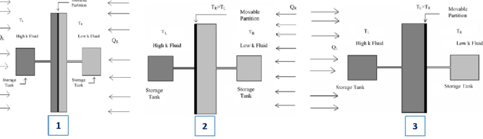
3 – Al-Nimr et al. (2009) designed a different solution to what they denominated by a ‘smart thermal insulation system’. The principle of functioning of this system is based on the idea of filling a gap inside a slab wall with rather a very low conductivity fluid (e.g. argon with k = 0.0179 W/m.K) when it’s needed to provide a good insulation or a very high conductivity fluid (e.g. water with k = 0.64 W/m.K) when the system is required to be a conductor. As shown in Figure 2.7, there are two storage tanks separated by a movable partition which moves to the left or to the right depending on the driving forces. When there is a need to have a system in insulating mode, the partition moves to the left to fill the gap with the low k fluid from the storage tank on the right. When the system needs to be in conduction state, it works the other way around, with the movable partition moving to the right [27].
2.2.1.3 – Active Insulation System
The Dutch company P&H Advisors proposed the concept of Active Insulation, which has the possibility to turn the insulation between an ‘on’ and ‘off’ functions [28], [29]. The principle of functioning and composition of this system are represented in Figure 2.8.
Figure 2.7 – Basic sketch of the smart thermal insulation system (1), in the insulating mode (2) and in the conduction mode (3). Change between modes is achieved via a movable partition on the slab wall [27]
In this Active Insulation system, a structure of air ducts is placed from the top to the bottom on both sides of a conventional hard insulation board. Inside them, two low voltage ventilators are placed, on the top and bottom of the board, to induce forced ventilation which will allow for heat or cold air to flow from outside to inside, or the other way around [28], [29]. This way, a short circuit is created between the two zones around the system bypassing the actual insulation board.
When the sun hits the outside wall, the air inside the ducts gets warmer. If heating is desirable, this air can be pumped by the ventilators towards the inner side of the insulation. For cooling is the other way around. Whenever the ventilator is switched on, the insulation board is turned off and vice-versa. If the ventilators were driven by a temperature sensor, the insulation could become an active element of heating and cooling buildings’ systems.
2.2.2 – Micro/Nano-scale actuation
Different approaches have been given either at a micro or nano scale to achieve dynamic insulation level. These solutions control thermal conduction by selecting different strategies: by varying gas pressure, the mean free path of gas molecules or gas-surface interaction in an insulation panel [12].
2.2.2.1 – Systems based on varying the pressure of a certain gas to
control conduction
1 - This is not a new concept, having been researched by Xenophou (1976) who submitted a patent about a system which controlled the thermal transfer by regulating the pressure of a partial vacuum between spaced steel panels which form a wall structure. By increasing the pressure of the vacuum, it was possible to decrease the heat flux through the walls, maintaining the ambient temperature in the structure (and the other way around) [30].
2 - Benson (1994) studied a variable-conductance vacuum insulation (VCI) material. In this insulation material, there is a small metal hydride connected to the vacuum envelope which reversibly absorbs/desorbs hydrogen. As illustrated in the graph of Figure 2.9, this hydrogen can change its pressure within a range from less than 10-6 to as much as 1 torr (1 torr ≃ 133.3 Pa), which allow to achieve a variable thermal
transmittance [31].
Dynamic Insulation as a strategy for Net-Zero Energy Buildings
12 João Tiago Lopes Alves Homem
3 – Horn et al. (2000) designed a switchable insulation system similar to the one developed by Benson. By using a metal hydride to change the pressure of hydrogen gas inside a panel, it is possible to reversibly change the thermal conductivity between 0.14 W/m.K in the conducting state and 0.003 W/m.K on the insulating state [32], [33], as illustrated in Figure 2.10.
4 - Berge et al. (2015), developed an insulation system with two different nano-porous materials where its internal pressure is varied to achieve a variable U-value. These materials were aerogel blanket and fumed silica (structure of a Vacuum Insulation Panels, VIP) and measurements of thermal conductivity were made when the air pressure was varied between 1 kPa and the atmospheric pressure (100 kPa) using a vacuum pump [9]. A variation of the thermal conductivity of around 3 times more for the fumed silica (7-19 mW/m.K) and less than 2 times for the aerogel blanket (11-17 mW/m.K) was measured (Figure 2.11).
2.2.2.2 – Systems based on varying the gas-surface interaction in an
insulation panel
Kimber et al. (2014), performed a conceptual analysis about a ‘smart’ multifunctional insulation, where it is possible to switch between insulating (Rins) and conducting states (Rcond), by varying the number of layers
of air (N) on a multi-layered polymer membrane, as depicted in Figure 2.12. Through each layer of air, there is heat transfer by convection and radiation (Rconv and Rrad in parallel) and through the interface
between layers there is heat transfer by conduction (Rp). By collapsing the wall and removing the air, it is
possible to change between insulated and conductive states, whereas radiation and convection resistances are no longer present. This way, it is possible to achieve a changeable thermal transmittance (U-value) [34].
Figure 2.11 – Schematic of the equipment for the measurements (on the left). Variation of the apparent thermal conductivity with the increase of air pressure for both materials (on the right) [9]
Figure 2.10 – Principle of functioning (on the left) (adapted from Burdajewicz, Korjenic, & Bednar, 2011) and range of variation of the thermal conductivity (on the right) [49]
2.2.2.3 - Systems based on varying the mean free path of gas molecules
in an insulation panel
Some recent studies have proved that by changing the direction of carbon nanotubes suspensions in a fluid it is possible to reversibly change the thermal conductivity. Wu et al (2014), studied the effect of varying the temperature on the change of direction of the carbon nanotubes. A change in thermal conductivity from 0.4 to 1.2 W/m.K was registered. [35]. Corinne Baresich et al. studied the effect of applying an external magnetic field to align the carbon nanotubes and consequently achieve a changeable thermal conductivity of the fluids where they are in a suspension [36]. This effect is illustrated in Figure 2.13.
Figure 2.12 – Illustration of adaptive multilayer wall: (a) is the insulated state, with N layers of air and its equivalent thermal resistance network is presented below (b); (c) is the configuration for collapsed wall or conductive state whereas (d) is its
equivalent thermal resistance [34]
Dynamic Insulation as a strategy for Net-Zero Energy Buildings
14 João Tiago Lopes Alves Homem
2.2.3 – Movable Insulation System: Thermocollect
Thermocollect is a movable insulation system that was developed and tested in Austria by Rudolf Schwarznayr. This is an active-façade system which is constituted by a set of automated movable panels placed in front of a massive wall. The system is automated according to the surrounding indoor and outdoor conditions and can reduce both the heat losses during the winter and the heat gains during the summer. During the winter, the system is typically closed at night in order to minimize the heat losses. However, during the day, in the presence of solar radiation, the panels are automatically opened to allow the solar heat to be stored in the wall. This heat will take a certain delay time to pass through the wall, but then will allow desirable heat gains inside the dwelling during nighttime (when the panels are closed). During the summer, the system is closed during the day acting as an insulation layer. During the night it can be opened to allow the release of unwanted heat gains accumulated during daytime [37]. An illustration of the principle of functioning of this system throughout a winter day is shown in Figure 2.14.
Figure 2.14 – Illustration of the way of functioning of the Thermocollect system [37] . In this system, the exterior movable panels can be either closed (1) or open (2). The goal is to modulate the thermal mass of the wall, as desirable throughout the day (3).
2.2.4 - Comparison
To conclude the state-of-the-art overview, a comparison between the dynamic insulation technologies is presented, in order to compare the range of adaptive control. This analysis is presented in Table 2.2.
Scale
Mechanism
of Control
Element Description
Range of adaptive control
Reference
λ [W/m.K] U-value [W/m2.K] Rc-value [m2.K/W]Macro
Heat convection through airParietodynamic wall – Void Space Dynamic Insulation
(VSDI)
--- 0.092-0.20 --- [17] Permeodynamic wall
(Breathing Wall) --- 0-0.21 --- [21] Translucent Dynamic
Insulation System: Façade element with switchable
insulation (FESU) --- 0.7-1.9 --- [7] Active InsulationTM --- --- --- [28] Heat convection through liquid Bi-directional thermodiode 0.07-0.35 --- --- [26] ‘Smart thermal insulation
system’: low and high conductivity fluid tanks
0.0179 (Ar) - 0.64 (H2O) --- --- [27]
Micro/
Nano
Varying the pressure of a gas to control heat conduction Variable conductance vacuum insulation (VCI) -Adsorption/deabsorption ofhydrogen
--- 0-9.0 --- [31] 0.003-0.14 --- --- [33] Variable pressure on aerogel
blanket 0.011-0.017 --- ---
[9] Variable pressure on fumed
silica (VIP) 0.007-0.019 --- --- Varying the
gas-surface interaction
‘Smart’ multifunctional insulation – Variation on the
number of layers of air
--- --- 0.118 – 3.70 [34]
Varying the mean free path of gas
molecules
Change in the temperature to vary the direction of the carbon nanotubes suspension
in liquid
0.4-1.2 --- --- [35]
External magnetic field applied to change the direction of the carbon
nanotubes
--- --- --- [36]
By analyzing the Table 2.2, it is possible to identify a classification challenge: in some elements the values available in literature for the adaptive range are in terms of λ whereas in others they are given in terms of U-value. It is really difficult to classify all these elements together because some refer to materials, which can be classified in terms of λ, or to a whole wall construction, which is classified in terms of U-value. Moreover, when it comes to dynamic systems, it all depends on how they are operated, the control strategy and the dynamic conditions. To conclude, the available information about each element is, most of the times, limited, which difficult even more this comparison.
Chapter 3 – Simulation approaches for performance prediction of
dynamic insulation elements
3.1 - Background
Throughout the few publications available regarding dynamic insulation modelling, the information accessible to help the BPS users to learn how to model these elements is somehow vague. This is caused by the fact that nowadays most of these BPS tools present some limitations regarding the simulation of time-variant parameters [16]. Despite the fact that there is a vast number of different software tools available to assess buildings’ performance, most of them were designed when the dynamicity of building materials/systems was not a central concern. Therefore, once the simulation is running, building shape and thermophysical material properties are not commonly changeable during this period, which difficult the modelling of those dynamic elements [10]. This way, it is important to develop a simulation assessment strategy to instruct the user on how to model elements which exhibit dynamic thermophysical parameters. From the software tools available, EnergyPlus is the one which had the most significant improvements in adaptive façade modelling capabilities [10]. This whole-building energy simulation software, developed by the US Department of Energy (DOE), had notorious developments since the introduction of a simplified programming language denominated as EnergyPlus Runtime Language (ERL), which allows to describe and specify the control algorithms. ERL grants the possibility to replicate a building energy management system (EMS) by means of a simulation tool [10].
3.2 – Tools available in EnergyPlus
When the BPS user wants to simulate a specific building, either in terms of energy demand or thermal comfort assessment, he must set the material properties of the elements of the several types of constructions on the building, as shown in Figure 3.1. However, by default, once the simulation is running, the user cannot influence or change the input parameters/properties during the process.
Dynamic Insulation as a strategy for Net-Zero Energy Buildings
18 João Tiago Lopes Alves Homem
In order to model dynamic insulation elements recurring to EnergyPlus software capabilities, there are two approaches that can be followed, depending on the type of insulation material/system which is going to be assessed through the simulation period. These two approaches are presented in the scheme of Figure 3.2.
Firstly, EnergyPlus can simulate movable/removable insulation systems, with the Class List
SurfaceControl: MovableInsulation. Moreover, EnergyPlus also allows to change the thermophysical
material properties by using Advanced Control Methods which emulates the behavior of a real building energy management system (EMS). This is possible using a set of sensors, control logics/algorithms and actuators, defined on several Class Lists available on Group Energy Management System (EMS) in EnergyPlus. On the following subchapters, these two approaches will be briefly described whereas some of implementation details will be referred. Moreover, some preliminary results about their application in EnergyPlus will be also outlined. To finish with, a critical comparison will be done to inform about some of the limitations of each approach.
3.2.1 – SurfaceControl: MovableInsulation Class List
3.2.1.1 – Brief description
The application of movable insulation in a building, has the purpose of either trap heat loads inside or to block heat from coming into the dwelling, at a certain desirable period of time. Using the Class List
SurfaceControl: MovableInsulation, included in Group Advanced Surface Concepts in EnergyPlus, it is
possible to schedule when to apply an extra layer of insulation on any construction, either on inside/interior, outside/exterior or even on both of its surfaces [38]. This can be scheduled for various times of a day, month or year, depending on how the user defines the schedule that control the behavior of these movable insulation elements. Moreover, MovableInsulation can only be applied on regular surfaces (wall, floor, roof, etc.), but not on windows, and it has the possibility for the external movable insulation to be transparent (TIM – transparent insulation material).
Figure 3.2 – Sketch of the different approaches used in EnergyPlus to model dynamic insulation elements, seen in terms of thermal resistances. The green resistances symbolize the ones being added and the red the ones being removed or
3.2.1.2 – Implementation details
As presented in Figure 3.3, there are four fields on this Class List:
• On ‘Insulation Type’, the user chooses if the movable insulation will be applied on either ‘Outside’ or ‘Inside’ of the surface, specified on the next ‘Surface Name’ field (from BuildingSurface:Detailed Class List). If it has to be applied on both surfaces, the user has to create two objects: one for the ‘Outside’ layer and another for ‘Inside’ layer.
• On ‘Material Name’ field, the user defines which is the material of the movable insulation layer (from
Material or MaterialNoMass Class Lists)
• On ‘Schedule Name’, a schedule is introduced by the user on the IDF Editor or it can be imported from a .txt or .csv file. This schedule should have a real number between 0.0-1.0, at each timestep of the simulation, which works as a fractional multiplier on the thermal resistance (Rc-value) of the material layer defined on the previous field. This way, when it is 1.0 the layer is added and when it is 0.0 the layer is removed.
As referred before, the schedule introduced can take real numbers between 0.0 and 1.0, which can also allow to model systems with changeable conductivity (
λ
), and consequently changeable Rc-value, throughout the simulation period.Knowing that the definition of Rc-value is the thickness (L) of the material divided by its conductivity,
L Rc
λ
, to model an element, with L constant, where it is possible to control its conductivity between
1
λ
(initial value of the material, introduced before the simulation) andλ
2, the user have to introduce the fractional multiplier resultant of the ratio , 2,1 Rc Rc 1 2
λ
λ
, at the desirable timesteps, on the schedule inputted.3.2.2 – Surface Construction State Actuator on EMS
3.2.2.1 – Brief description
The second option to model dynamic insulation elements is through a high-level control method available in EnergyPlus: Energy Management System (EMS) [38]. EMS uses EnergyPlus Runtime programming language to emulate the controls available in digital energy management systems used in real buildings. These real world systems, composed by sensors, control units/logics and actuators, can be used to control several buildings’ systems, which include heating, cooling, ventilation, lighting, on-site power generation, mechanized systems for shading devices, window actuators and façade elements [39].
Figure 3.3 – Example of an application of the Class List SurfaceControl: MovableInsulation on IDF Editor. In this case, exterior movable insulation, in all surfaces of the building (S, N, W, E) is controlled according to a specific Summer Control
Dynamic Insulation as a strategy for Net-Zero Energy Buildings
20 João Tiago Lopes Alves Homem
The class lists available in the EMS group on EnergyPlus are shown in Figure 3.4.
Making use of sensors, control algorithms and actuators, EMS overrides specific aspects of EnergyPlus behavior [38]. Firstly, sensors reuse EnergyPlus output variables by measuring a certain parameter regarding the thermal environment. Afterwards, a control algorithm is defined by the user in order to control a certain actuator, based on the information which was provided by the sensors. By means of IF-ELSEIF-ELSE-ENDIF blocks, it will set the behavior of the actuator by proposing a certain action [40]. This process is illustrated in Figure 3.5.
There are several groups of actuators available in EMS, which can be introduced in the class list
EnergyManagementSystem:Actuator. The ones which allow to control thermo-optical properties of the
materials are regarding the Thermal Envelope [40]. The actuators available on this group, allow to control and model several building envelope adaptive elements. One of them is the Surface Construction State actuator which is able to model elements with variable thermo-optical material construction properties [40]. This allow to make insulation changeable in the simulation environment. When modelling a certain element with changeable material properties, the Surface Construction State acts by changing all the existing construction for another which includes a different state of the element, instead of only acting at a material scale. This way, different construction with different thermophysical properties must be created to be used in a sequence defined by the control algorithm.
Figure 3.5 – Schematic that presents the main components of an Energy Management System (EMS) and displays the way of functioning in order to control a dynamic insulation system
3.2.2.2 – Implementation details
To the best of our knowledge, there is no simulation strategy available in literature to inform the user of how to model dynamic insulation elements in a simulation environment. This way, a step-by-step procedure of how to use the Surface Construction State Actuator in EMS was given in this subchapter.
Considering a certain insulation element, to be installed on the outside of the exterior walls of a building, that can change its conductivity from
λ
1 toλ
2when the temperature indoors (Tin) is higher than thetemperature outdoors (Tout).
1st step: Define two different materials on Class List Material: one with conductivity
1
λ
and another with 2λ
.2nd step: Define the construction layers’ sequence of the exterior walls on Class List Construction, for both
two cases
3rd step: Define which construction is chosen to start the first simulation timestep as the standard for all the
wall surfaces (on BuildingSurface:Detailed Class List):
4th step: Define in Class List EnergyManagementSystem:Sensor T
in and Tout as sensors for EMS
5th step: In the Class List EnergyManagementSystem:ConstructionIndexVariable, both constructions
defined in step 3 are declared as EMS variables which identify construction states for the program.
6th step: In EnergyManagementSystem:Actuator, the surfaces which have the dynamic insulation element
incorporated, are inputted for EMS and this way identified as actuators
7th step: The control algorithm is introduced in EnergyManagementSystem:Program, which define how the
actuator behaves throughout the simulation: • IF Tin > Tout
• SET ConstructionActuator = Construction
λ
2 • ELSE SET ConstructionActuator = Constructionλ
1.8th step: Finally, the program created in the previous step is declared and used as an input for EMS controls
(on Class List EnergyManagementSystem:ProgramCallingManager).
Figure 3.6 – Example of an application of the Class List EnergyManagementSystem:Actuator which sets each surface as Surface: Construction State Actuators
Dynamic Insulation as a strategy for Net-Zero Energy Buildings
22 João Tiago Lopes Alves Homem
3.2.3 – Preliminary results
In order to get familiar with the simulation tools and to understand if both approaches work the way it was expected, there is a need to get preliminary simulation results with a simple reference case. This way, the BESTEST Case 600 test building was selected to perform these analyses. This basic test building is a lightweight simple single-zone building which is assessed with a weather file from Denver, Colorado (USA) and has as temperature setpoints 20ºC for heating and 27ºC for cooling [41].
3.2.3.1 – MovableInsulation Actuator
In order to show the transition, in terms of temperature and energy demand, that occurs when MovableInsulation is used to change between insulated and non-insulated states, a simple scenario was designed. Based on schedules previously defined, the goal is to show that it is possible to change from one state to another throughout the simulation.
Two different periods were studied: one in the winter (21st-22nd of December) where the heating rate was
assessed and another in the summer (21st- 22nd of June). For these two periods, three different scenarios
were chosen:
• Always OFF, where the insulation layer was removed from the wall construction during the chosen period;
• Always ON, where the insulation layer is placed in the construction the same way as described in BESTEST Construction;
• 2nd Day OFF, where the insulation was only removed on the second day of the respective period.
The procedure followed for the summer period is illustrated in Figure 3.7.
Figure 3.7 – Methodology followed for the 2nd Day OFF Scenario at the summer period. Firstly the schedule described was
Figure 3.9 – Results from all the scenarios compared on the same plot for the summer period Figure 3.8 – Results from all the scenarios compared on the same plot for the winter period
Dynamic Insulation as a strategy for Net-Zero Energy Buildings
24 João Tiago Lopes Alves Homem
On the winter period, illustrated in Figure 3.8, it is possible to observe the transition between one state and another in both periods (highlighted by the grey area in the graph). On the summer period, illustrated in Figure 3.9, the transition between Always ON and Always OFF states can be observed on the temperature graph whereas on the winter period the transition is observed on the heating rate profiles.
3.2.3.2 – Surface Construction State Actuator
In order to illustrate the way how this surface construction state actuator works inside the EMS and the effect it has on the output variables, a specific scenario with a specific control strategy was defined. Once more, it was used the BESTEST Case 600 as an input for the parameters of the model.
As control strategy, it was defined that when the temperature outdoors was higher than 25ºC, the actuator would change the standard BESTEST construction with a layer of insulation of 0.04 W/m.K of thermal conductivity (which I named Walls_LowCond) for another construction with a layer of insulation of 0.08 W/m.K (Walls_HighCond), at all the surfaces of the building. This algorithm introduced in the Program class list of EMS is presented in Figure 3.10.
The period chosen was between the 24th and 26th of August, and total cooling capacity was limited by 40%
in order to allow a more significant variation on the indoor temperature.
Figure 3.11 – Graph which illustrates the variability of the indoor temperature according to the EMS control strategy defined Figure 3.10 – EMS Program to change between low and high conductivity states
![Figure 1.1 – The path toward a Net-Zero Energy Building: first follow the efficiency path and then cover the remaining energy demand by installing renewable energy sources [3]](https://thumb-eu.123doks.com/thumbv2/123dok_br/19194975.951397/17.918.276.591.666.965/figure-energy-building-efficiency-remaining-installing-renewable-sources.webp)
![Figure 1.2 – Illustration of dynamic energy flows and interactions in buildings with adaptive facades (from: IEA EBC Annex 44, adapted by Fernández Solla [47])](https://thumb-eu.123doks.com/thumbv2/123dok_br/19194975.951397/18.918.233.669.639.888/figure-illustration-dynamic-interactions-buildings-adaptive-facades-fernández.webp)
![Table 2.1 – Comparison between traditional and state-of-the-art insulation materials [14]](https://thumb-eu.123doks.com/thumbv2/123dok_br/19194975.951397/21.918.153.767.733.1013/table-comparison-traditional-state-art-insulation-materials.webp)
![Figure 2.2 – Dynamicity of the U-value according the air flow velocity through a breathing wall [21]](https://thumb-eu.123doks.com/thumbv2/123dok_br/19194975.951397/23.918.293.624.585.828/figure-dynamicity-value-according-flow-velocity-breathing-wall.webp)
![Figure 2.4 – Variation of the U-value in both insulating and conducting state depending on the indoor-outdoor temperature difference [7]](https://thumb-eu.123doks.com/thumbv2/123dok_br/19194975.951397/24.918.157.759.478.747/figure-variation-insulating-conducting-depending-outdoor-temperature-difference.webp)


![Figure 2.11 – Schematic of the equipment for the measurements (on the left). Variation of the apparent thermal conductivity with the increase of air pressure for both materials (on the right) [9]](https://thumb-eu.123doks.com/thumbv2/123dok_br/19194975.951397/28.918.115.804.207.452/schematic-equipment-measurements-variation-apparent-conductivity-increase-materials.webp)
![Figure 2.13 – Study of the variation of the thermal conductivity in regard with different nanotube orientations [36]](https://thumb-eu.123doks.com/thumbv2/123dok_br/19194975.951397/29.918.151.779.708.965/figure-study-variation-thermal-conductivity-different-nanotube-orientations.webp)
