(Annals of the Brazilian Academy of Sciences) ISSN 0001-3765
www.scielo.br/aabc
Effect of thermo-coupled processes on the behaviour
of a clay barrier submitted to heating and hydration
MARCELO SÁNCHEZ1, ANTONIO GENS2 and SEBASTIA OLIVELLA2 1Department of Civil Engineering, University of Strathclyde, 107 Rottenrow, G4 0NG Glasgow, UK 2Department of Geotechnical Engineering and Geosciences, Universitat Politècnica de Catalunya, (UPC),
Gran Capita s/n, Campus Nord Edificio D2, 08034 Barcelona, Spain Manuscript received on June 17, 2008; accepted for publication on May 14, 2009
ABSTRACT
The storage of high level radioactive waste is still an unresolved problem of the nuclear industry, being geological disposal the most favoured option and, naturally, the one requiring the strongest geo-mechanical input. Most concep-tual designs for the deep geological disposal of nuclear waste envisage placing the canisters containing the waste in horizontal drifts or vertical boreholes. The empty space surrounding the canisters is filled by an engineered barrier often made up of compacted swelling clay. In the barrier and the near field, significant thermo-hydro-mechanical (THM) phenomena take place that interact in a complex way. A good understanding of THM issues is, therefore, necessary to ensure a correct performance of engineered barriers and seals. The conditions of the bentonite in an engineered barrier for high-level radioactive waste disposal are being simulated in amock-upheating test at almost scale, at the premises of CIEMAT in Madrid. The evolution of the main Thermo-Hydro-Mechanical (THM) variables of this test are analysed in this paper by using a fully coupled THM formulation and the corresponding finite element code. Special emphasis has been placed on the study of the effect of thermo-osmotic flow in the hydration of the clay barrier at an advanced staged of the experiment.
Key words:expansive clays, heating test, nuclear waste disposal, thermo-hydro-mechanical coupled analysis.
INTRODUCTION
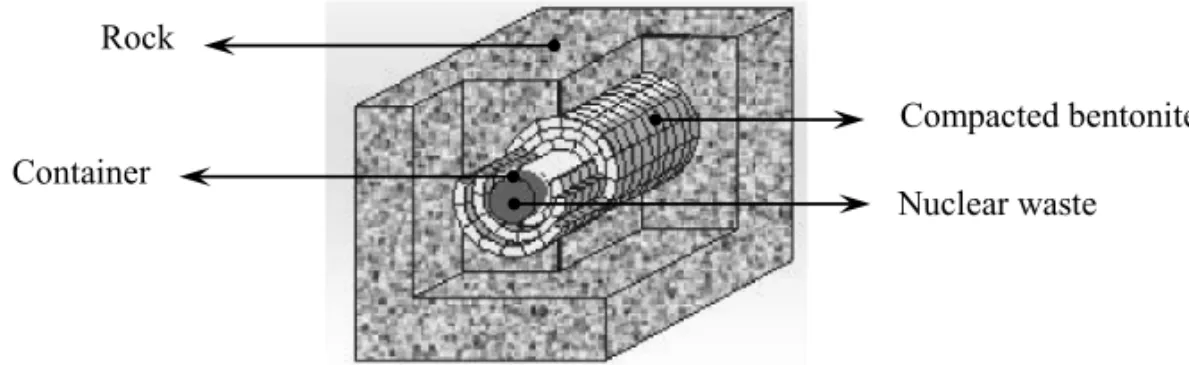
Conceptual designs for deep geological disposal of nu-clear waste generally envisage placing the canisters containing the waste in horizontal drifts or vertical bore-holes. The empty space surrounding the canisters is filled by an engineered barrier often made up of compacted bentonite in the form of blocks (Fig. 1). This clay-based isolation system has the multiple purposes of providing mechanical stability for the waste canister (by absorbing stresses and deformations); serving as a buffer around
Selected paper presented at the IUTAM Symposium on Swelling and Shrinking of Porous Materials: From Colloid Science to Poro-mechanics – August 06-10 2007, LNCC/MCT.
Correspondence to: Marcelo Sanchez
Present address: Zachry Department of Civil Engineering. Texas A&M University, 3136 TAMU, College Station, US
E-mail: [email protected]
it; sealing discontinuities in the emplacement boreholes and drifts; and delaying the water flow from the host rock. The barrier behaviour is highly complex, since it involves coupled Thermo-Hydro-Mechanical (THM) phenomena that take place due to the simultaneous heat-ing (generated by the radioactive waste) and hydration (due to the contribution of the surrounding rock) of the barrier. A good understanding of THM issues is, there-fore, necessary to ensure a correct performance of engi-neered barriers and seals.
Rock
Compacted bentonite
Container
Nuclear waste
Fig. 1 – Scheme of the engineered barrier.
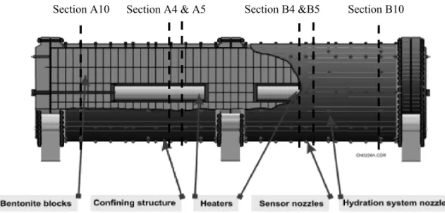
in situ test, under natural conditions and at full scale (Grimsel, Switzerland); a mock-up test, at almost full scale (CIEMAT, Madrid); and a series of laboratory tests to complement the information from the two large-scale tests. This paper focus mainly on the mock-up exper-iment, which avoids many of the uncertainties arising from the natural system. This is achieved mainly due to the good control of the initial and boundary conditions of the experiment. Two electrical heaters (simulating can-isters containing heat-emitting waste) were placed in the centre of a steel cylinder 6 m long and with inner diame-ter of 1.62 m. The space between the headiame-ters and the steel cylinder was filled with a 0.64 m-thick engineered barrier made up of compacted FEBEX bentonite (Fig. 2). The barrier is hydrated uniformly from all around the cylinder with an applied water pressure of about 0.5 MPa. Simul-taneously, the barrier was heated maintaining a constant temperature of 100◦C at the contact between heaters and bentonite. This very well instrumented test has provided the opportunity to study in detail the evolution of the main THM variables for a period of almost ten years.
The evolution of the main THM variables of the mock-uptest has been analysed using theCODE_BRIGTH
program (Olivella et al. 1996), which is a finite ele-ment code developed to handle coupled THM problems in porous media. An unexpected decay in the rate of hydration observed at advanced stages of the test has affected significantly the predictions performed using ‘standard THM models’. The difference between model outputs and experimental results affect the reliability of the long-term predictions, especially the one related to the time required to reach the full saturation of the clay barrier. Due to that, the studies have been oriented to-wards the identification of other processes or phenom-ena, which can clarify and explain, with physical basis,
the ‘unexpected’ behaviour of the clay barrier. A prelim-inary study has envisaged three main phenomena that are identified as: thermo-coupled effects, threshold gradient and evolution of the micro-fabric (Sánchez 2004). This paper focus on the analysis of the first phenomenon.
The paper is organized as follows: first the expan-sive clay used in the analysis is introduced; then, the general framework adopted to analyse the heating test is presented; afterwards, the main results of the numerical analyses are introduced; and finally, the paper closes with the main conclusion of this work.
MATERIALS
The clay barrier of themock-uptest has been built with the FEBEX bentonite, which was selected by ENRESA (the Spanish Agency for Radioactive Waste Manage-ment) as suitable material for the backfilling and sealing oh high level nuclear waste repositories. The FEBEX bentonite was extracted from the Cortijo de Archidona deposit (Almería, Spain). The processing of the ma-terial at the factory consisted in its disaggregation and gently grinding, drying at 60◦C and sieving by 5 mm. For the large-scale tests of the FEBEX Project, the ben-tonite blocks were manufactured by uniaxial compaction of the granulated clay with its hygroscopic water content, at dry densities close to 1.7 g/cm3(ENRESA 2000). The
Section A4 & A5 Section B4 &B5 Section B10 Section A10
Fig. 2 – Layout of the large scale heating test.
The FEBEX bentonite has a content of montmoril-lonite higher than 90 percent. Besides, it contains vari-able quantities of quartz, plagioclase, K-feldspar, cal-cite and opal-CT (cristobalite-trydimite). The cation ex-change capacity (CEC) varies from 96 to 102 meq/100g, and the major exchangeable cations are: Ca (35-42 meq/ 100g), Mg (31-32 meq/100g), Na (24-27 meq/100g) and K (2-3 meq/100g).
The liquid limit of the bentonite is 102±4 percent, the plastic limit is 53±3 percent, the specific gravity 2.70±0.04, and 67±3 percent of particles are smaller than 2μm. The hygroscopic water content in equilibrium
with the laboratory atmosphere is 13.7±1.3 percent. The
value obtained for the external specific surface area using the BET technique is 32±3 m2/g and the total specific surface area obtained using the hygroscopicity method is about 725 m2/g. The analysis of the mercury intrusion
data reveals that the intra-aggregate pores (smaller than 0.006νm) represents the 73-78 percent of total pore
vol-ume when the bentonite is compacted at a dry density of 1.7 g/cm3.
THEORETICAL FORMULATION AND COMPUTER CODE
An appropriate way to integrate the coupled THM phe-nomena and their mutual interactions that take place in expansive clays submitted to simultaneous heating and hydration is by means of a properly designed theoret-ical formulation. The THM formulation proposed by Olivella et al. (1994) has been adopted in this work as a general framework for the analysis of the results of the
thermo-hydraulic tests. A brief description of the formu-lation is presented below.
The theoretical framework is composed of three main parts: balance equations, constitutive equations and equilibrium restrictions. The framework is formulated using a multi-phase, multi-species approach. The sub-scripts identify the phase (‘s’ for solid, ‘l’ for liquid and ‘g’ for gas). The superscript indicates the species (‘h’ for mineral, ‘w’ for water and ‘a’ for air). The liquid
phase may contain water and dissolved air, and the gas phase may be a mixture of dry air and water vapour.
BALANCEEQUATIONS
Equations for mass balance were established following the compositional approach, which consists of balancing the species rather than the phases. The mass balance of solid present in the medium is written as:
∂
∂t ρs(1−φ)
+ ∇ ∙ ρs(1−φ)u˙=0 (1)
whereρsis the mass of solid per unit volume of solid,φ is the porosity;js is the flux of solid,t is time,∇is the divergence operator andu˙is the solid velocity vector.
Water is present in liquid and gas phases. The total mass balance of water is expressed as:
∂
∂t
θlwSlφ+θgwSgφ+ ∇ ∙jlw+jwg= fw (2)
whereθlw andθgw are the masses of water per unit
(α = l,g); jlw andjwg denote the total mass fluxes of
water in the liquid and gas phases (water vapour) with respect to a fixed reference system; and fwis an external supply of water.
Dry air is considered as a single species and it is present in liquid and gas phases. The total mass balance of dry air is expressed as:
∂ ∂t
θlaSlφ+θgaSgφ+ ∇ ∙jal +jag= fa (3)
whereθla andθgaare the masses of dry air per unit
vol-ume of liquid and gas, respectively;Sαis the volumetric
fraction of pore volume, occupied by the alpha phase
(α =l,g);jal andjagdenote the total mass fluxes of dry
air in the liquid and gas phases with respect to a fixed reference system; and fais an external supply of dry air. Regarding the thermal problem, the equilibrium be-tween the phases is assumed. Therefore, the temperature is the same for all the phases. Consequently, only one equation is needed for the energy balance. The total inter-nal energy, per unit volume of porous media, is obtained adding the internal energy of each phase corresponding to each medium. Applying the balance equation to this quantity, the following equation is obtained:
∂
∂t Esρs(1−φ)+Elρl pSlφ+EgρgSgφ
+∇ ∙ ic+jEs+jEl+jEg= fE
(4)
where Es is the solid specific internal energy; El and Egare specific internal energies corresponding to liquid and gas phases, respectively; ρs is the solid density; ρl andρg are the liquid and gas phase densities; ic is the conductive heat flux; jEs is the advective energy flux of solid phase with respect to a fixed reference system;
jEl andjEg are the advective energy flux of liquid and gas phases, respectively, with respect to a fixed reference system; fE are the energies supply per unit volume of medium.
Finally, the balance of momentum for the porous medium reduces to the equilibrium equation in total stresses:
∇ ∙σσσ +b=0 (5)
whereσσσ is the stress tensor andbis the vector of body
forces. This assumption is usually accepted because both velocities and accelerations are small, yielding terms
that are negligible in comparison with the stress terms. Through an adequate constitutive model, the equilibrium equation is transformed into a form expressed in terms of the solid velocities, fluid pressures and temperatures. The assumption of small strain rate is also made.
CONSTITUTIVEEQUATIONS
The constitutive equations establish the link between the independent variables (or unknowns) and the dependent ones. A more detailed explanation of the mathematical formulation in general and constitutive equations in par-ticular is given in Gens et al. (1998). The constitutive laws and the corresponding parameters presented in the section correspond to the case use in the numerical anal-ysis coded as ‘OBC’ (Operational Base Case). Mode details in section 4.2.
Hydraulic problem
The advective flows of the phases (i.e., liquid or gas), with respect to the solid phase, are assumed to follow Darcy’s law:
qα = −Kα ∇Pα−ρρραg; α=l,g (6)
wherePlandPgare liquid and gas pressure, respectively;
ρl is the liquid density; ρg is the gas density; g is the gravity vector; andKα is the permeability tensor of the
alpha phase(α=l,g), which is given by:
Kα =k
krα μα
; α=l,g (7)
The intrinsic permeability tensor (k) depends on the pore structure of the porous medium. krαis the value of
rel-ative permeability that controls the variation of perme-ability in the unsaturated regime, andμαdenotes the
dy-namic viscosity.αmay stand for eitherlorg, depending on whether liquid or gas flow is considered.
The saturated permeability to deionised water,k(7), of samples of untreated FEBEX bentonite compacted at different dry densities, can be related with porosity through a modified Kozeny’s law according to:
k=k0 φ
3
(1−φ)2
(1−φ0)2
φ03 I (8)
wherek0is the intrinsic permeability corresponding to
adopted together with experimental data obtained for FEBEX bentonite permeated at room temperature with deionised water. A k0=1.9 e–21m2for a reference
poros-ity(φ0)of 0.40 has been adopted. It was checked that
the permeability of the FEBEX bentonite to granitic wa-ter (salinity 0.02%) is analogous to that obtained for deionised water (Villar 2002).
Fig. 3 – Variation of saturated permeability with porosity. Experimen-tal data and adopted model for the intrinsic permeability law.
The relative permeability of liquid(krl)phases is
made dependent on Se (effective degree of saturation) according to:
krl =Sen (9a)
Se= Sl−Slr
Sls −Slr (9b)
whereSlis degree of saturation;Slr andSlsare residual and maximum degree of saturation, respectively; andn is a material parameter. Based on back-analyses (per-formed with CODE_BRIGHT) of isothermal infiltration tests, a cubic law (i.e. n=3) has been adopted for this law (Lloret et al. 2002, Pintado et al. 2002).
The retention curve of the bentonite was determined in samples compacted to different dry densities (Lloret et al. 2004). The volume of the samples remained con-stant during the determinations, since they were confined in constant volume cells. To impose the different rela-tive humidities, the cells were placed in desiccators with sulphuric acid solutions of various concentrations. A
modified van Genuchten law has been adopted to model the dependence of the degree of saturation on suction.
Se=
1+
s P0
1−1λ
0
−λ0
fd;
where: fd=
1− s Pd
λd
(10)
wheres(s = Pg−Pl)is the suction; P0is a parameter related to the capillary pressure (the air entry value); and
λ0is a parameter that controls the shape of the curve (van Genuchten 1978). The function fdis included to obtain more suitable values at high suctions;Pd is a parameter related with the suction at 0 degree of saturation; andλd is a model parameter (when it is null, the original model is recovered). Figure 4 presents the retention curves ob-tained with these expressions for different values of dry density together with the experimental data. The adopted parameters are: P0 =28 MPa,λ0 =0.18, Pd =1100 MPa,λd = 1.1 andη =0.7. The relation betweenP0 and surface tension(σ )suggested by Olivella and Gens
(2000) has been extended to this model, that is:
P0=PT0σT
σT0
(11)
where the surface tension (in N/m) has been obtained fitting values of surface tension with the following ex-pression (Olivella 1995):
σT =0.03059exp
252.93
273.15+T0
(12)
By varyingP0in accordance with this expression, a de-pendence of the retention curve with temperature is in-troduced. Therefore, suction will decrease with temper-ature for a given degree of saturation (Olivella and Gens 2000). Experimental results have shown that, in most cases, the influence of temperature on retention curve is small (Lloret et al. 2004).
The molecular diffusion of vapour water in gas phase is governed by Fick’s law, through:
iw
g = −Dwg∇ωgw= − φρgSgτDmwI+ρgD′g
∇ωwg (13)
whereiw
g is the non-advective mass flux of water in gas;
Dw
0.1
1.0
10.0
100.0
1000.0
0.00
0.20
0.40
0.60
0.80
1.00
Degree of saturation
S
u
ct
ion
(
M
P
a)
> 1.75[1.75 , 1.70]
[1.70 , 1.65]
[1.65 , 1.60]
[1.60 , 1.55]
Model Dry density (Mg/m3)
Fig. 4 – Retention curve adopted in the analyses, together with the experimental data for FEBEX bentonite (symbols).
dispersion tensor. Dw
m is the molecular diffusion coeffi-cient of vapour in gas. A tortuosity factor of 0.8 has been adopted based on numerical back analysis of heat flow tests at constant overall water content (Lloret et al. 2002, Pintado et al. 2002).
Thermal problem
The Fourier’s law has been adopted for the conductive flux of heat. Thermal conductivity depends on the hy-dration state of the clay and is expressed by a variant of the geometric mean:
ic= −λ∇T (14)
where
λ=λse satλ
(1−se)
dr y (15)
and
λdr y=λ(soli d1−φ)λ
φ
gas; λsat =λ(soli d1−φ)λ
φ
li q (16)
where λis the thermal conductivity. The thermal
con-ductivityλ[W/m∙K](14) of the compacted bentonite at laboratory temperature is related to the degree of sat-uration (Se)(15). Figure 5 presents the experimental
values obtained for the FEBEX bentonite together with the model result computed using (15) and (16). A value of 0.47 has been adopted for λdr y and 1.15 for λsat. More details can be found in Sánchez and Gens (2006).
0.20
0.40
0.60
0.80
1.00
1.20
1.40
1.60
0.00 0.20 0.40 0.60 0.80 1.00
Degree of saturation
T
h
er
m
al
c
on
d
u
ct
ivi
ty (
W/
m
º
C
)
Measurements
Model
Fig. 5 – Thermal conductivity: FEBEX bentonite experimental results (symbols) and model fitting.
Mechanical problem
The mechanical constitutive law adopted is the Barcelona Basic Model (BBM). This model extends the concept of critical state to the unsaturated conditions, including the dependence of yield surface on suction. Two stress variables are considered: the net stresses(σ−Pgm)and
capillary suction. Net stress is the excess of total stress over gas pressure. If full saturation is achieved, net mean stress becomes effective stress. The main equations are introduced as follows, more details are provided in the Appendix. For simplicity, net stress will also be denoted byσ. It is assumed that the generalised yield surface
depends not only on stresses and history variables, but on temperature and suction, as follows:
F= 3J 2 g2y −L
2
y(p+Ps)(Po−p)=0 (17)
where M is the slope of the critical state; pois the ap-parent unsaturated isotropic pre-consolidation pressure; g is a function of Lode’s angle; and ps considers the dependence of shear strength on suction and tempera-ture (see Appendix). The hardening law is expressed as a rate relation between volumetric plastic strain and the saturated isotropic pre-consolidation stress, (p0∗, Fig. 6), according to:
˙ p0∗ p0∗ =
(1+e) λ(0)−κ
˙
whereeis void ratio;κ is the elastic compression index
for changes in net mean stress; andλ(0)is the
compres-sion index for changes in net mean stress for virgin states of the soil in saturated conditions. More details about BBM can be found in the elsewhere (Alonso et al. 1990, Gens 1995).
p0
ps
s
p*0
p
J
LC
Fig. 6 – A three-dimensional representation of theBBMyield surface. Due to the high compaction the bentonite blocks have been subjected to, the description of the behaviour of the material inside the yield surface is particularly important. The variation of stress-stiffness with suction and, especially, the variation of swelling potential with stress and suction have been considered (Sánchez and Gens 2006). The resulting elastic model is the following:
˙
εve= κi
(1+e)
˙ p p +
κs
(1+e)
˙ s
(s+0.1)
+ α0+α21TT˙
(19)
˙
εes = ˙ J
G (20)
where
κi =κi 1+αss (21)
κs =κs0 1+αsplnp/pr e f
(22)
G= E
2(1+v) (23)
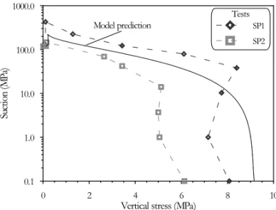
where E is the young module. Figure 7 presents the model results in a swelling pressure test. The stress path prescribed in the simulation is similar to the one fol-lowed by a point located close to the heater, that is, an
initial drying (in this case close to the 200 MPa) and, then, a wetting. In the same figure, the results of the swelling pressure tests coded as SP1 and SP2 are shown. Test SP1 and SP2 are described in detail in Lloret et al. (2003). The model results can be considered satisfac-tory, the stress path is quite well reproduced, as well as the predicted value of the swelling pressure. The main model parameter are summarised in Table I. More details can be found in Sánchez and Gens (2006).
Fig. 7 – Computed stress path for swelling pressure tests using the BBM. SP1 and SP2 experimental results are provided for comparison.
TABLE I
Model parameters related to the mechanical prob-lem (defining the Barcelona Basic Model).
κ 0.04 κs 0.25
ν 0.4 αi s –0.003
αsp –0.147 αss 0.00
αo 1.5×10⁻⁴(◦C−1) α2 0.00
λo 0.15 pc 0.10 MPa
p∗o 14 MPa α 0.395
r 0.75 β 0.05
M 1.5 To 20◦C
k 0.1 ρ 0.2
EQUILIBRIUMRESTRICTIONS
in phases (liquid, gas). This assumption is sufficiently adequate because these chemical processes are fast com-pared to the transport processes that take place in porous media and, for this reason; they are not rate-controlled. In this problem, the concentration of water vapour in the gas phase is controlled by the psychometric law, and the solubility of dry gas in water is given by Henry’s law (Olivella et al. 1994).
COMPUTERCODE
The mathematical formulation presented above has been implemented in the finite element computer pro-gram BRIGHT (Olivella et al. 1996). CODE-BRIGHT is a tool designed to analyse numerically cou-pled THM problems in geological media. One unknown “state variable” is associated with each of the balance equations presented in Section 3.1 (Equations 1 to 5). The unknowns are obtained by solving the system of PDE’s (Partial Differential Equations) numerically in a coupled way. From state variables, dependent variables are calculated using the constitutive equations or the equilibrium restrictions. The numerical approach can be viewed as divided into two parts: spatial and tem-poral discretization. Galerkin finite element method is used for the spatial discretization, while finite differences are used for the temporal discretization. The discretiza-tion in time is linear, and an implicit scheme is used. Finally, since the problem presented here is non-linear, the Newton-Raphson method was adopted as an iterative scheme. More details can be found in Olivella (1995) and CODE_BRIGHT User’s Manual (2008).
RESULTS
INTRODUCTION
A 2-D axis-symmetric model has been adopted for the numerical analysis of the mock-uptest. The study has been focused on two characteristic cross-sections: ‘hot’ and ‘cold’ cross-section. The first one corresponds to a section in the heater zone (i.e., Section A4 and B4, Fig. 2). The second one is located away from the heater (Section A10 and B10, Fig. 2). In this way, two differ-ent patterns of behaviour can be examined. A complete analysis of the test, including other section, can be found in Sánchez and Gens (2006). The experimental values used in the analyses have been supplied by CIEMAT.
The adopted initial and boundary conditions are intro-duced as follows.
INITIALCONDITIONS
The initial global degree of the saturation of the mock-uptest just before the switch on of the heater was 71.50%. The same initial degree of the saturation has been assumed in the model. An initially uniform tem-perature of 20◦C is assumed in the entire domain. This is consistent with CIEMAT Report (2002) data. As for the mechanical problem, a hydrostatic value of 0.11 MPa has been adopted for the initial stress, approximately equal to the weight of the bentonite in the mid diame-ter of the buffer.
Boundary conditions
A water pressure of 0.55 MPa is applied in the external boundary in accordance with CIEMAT Report (2002) data. For the mechanical problem, a stress free outer boundary has been prescribed. Finally, for the ther-mal boundary conditions at a radius equal to 0.15 m (radial coordinate of the heater elements), the applied conditions are as follows: i) 0-6 days: constant power (250 W/heater); ii) 6 days –t100: constant power (500 W/heater); iii)t100: T =100◦C. Wheret100is the time at which the temperature reaches 100◦C at some point in the bentonite (15.6 days for the analysis presented herein). On the external boundary, the following radia-tion condiradia-tion has been applied:
je=γe(T0−T) (24) where je is the heat flow, T0is the prescribed temper-ature (T0 = 20◦C) andγ
e is the radiation coefficient. A coefficientγe =5 has been adopted. This value has been adjusted in order to ensure the prescribed condition
(T0)on the outer boundary. BASECASEANALYSIS
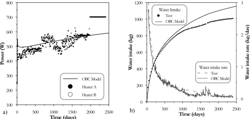
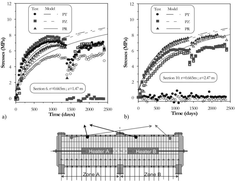
b) present the evolution of the global variables of the problem, which are: a) the heater power and b) the wa-ter intake. Figures 9 a) and b) show the time evolution of temperature at different points of the barrier, whereas Figures 9 c) and d) present the evolution of the rela-tive humidity at different radii of the barrier for the two selected sections. Finally, Figures 10 a) and b) show the time evolution of stresses in selected positions of the barrier (PT: tangential stress, PZ: longitudinal stress
and PR: radial stress). In the following sections, the
main results (experimental and numerical) of the mock-uptest are analysed considering the different problems (thermal, hydraulic and mechanical) in a separately way.
Thermal problem
The barrier is heated maintaining a constant maximum temperature of 100◦C at the contact between heaters and bentonite. It can be stated that the model yields good results regarding the thermal problem. This is reflected either in the evolutions of a global variable (i.e., power emitted by the heaters on Fig. 8 a), or in the measures of the local ones (such as the evolution of temperatures in different points of the test Figs. 9 a) and b). It can be noted that there are some small differences in the tem-perature field, especially in zones close to the heater. They may be an effect of the lower thermal conductivity in the discontinuity that may exist between heater and bentonite.
Hydraulic problem
The barrier is hydrated uniformly from the periphery, maintaining a practically constant water pressure of about 0.5 MPa. Figure 8 b) shows the time evolution of the water entry in the test and the rate of the water intake as well. Good model predictions can be observed at the beginning of the experiment, but overestimation of the water entry is computed at advances stages. Figures 9 a) and b) show the evolution of the relative humidity. It can be seen that until the day 900 of the test, approxi-mately, the model offers a good reproduction of the hy-draulic variables. Up to that time, the overall behaviour of the test is the expected one: an increasing saturation in the zones close to the hydration boundary and an intense drying in the regions close to the heaters followed by a
slow hydration. The behaviour of zones close to a radius of 0.37 m shows an initial wetting, due to the conden-sation of the water vapour coming from the inner region and, then, a drying.
From about the day 900, some differences are ob-served between the hydraulic behaviour of the test and model predictions. In terms of the water entry, the model results move away progressively, in relation to the ex-perimental data. This fact can be clearly detected in terms of the rate of the water intake (Fig. 8 b)), in which the test data values (from the day 900 of the test) un-dergo an important reduction in comparison with the values of the ‘OBC’ model. A recovery of the exper-imental values can be seen when a non-planned event took place (the overheating episode, close to the day 1381; for more details, see Sánchez et al. 2005). Finally, the tendency observed previous to the overheating was recovered, that is, a clear slowing down of the rate of the water intake compared to the model predictions.
Regarding the evolution of the relative humidity in the heater regions Sections A4 and B4, Figure 9 c), a significant reduction in the rate of the relative humid-ity increase can be observed. The effects of the over-heating can be clearly noted in the ‘hot cross-section’, especially just after this episode. It seems that the tran-sient period induced by the overheating was practically finished after the day 1700. On the other hand, when a ‘cold cross-section’ is examined, the hydration problems are less perceptible (Sections A10 and B10, Figure 9 d). Note that some small differences between model and test results can also be detected in these sections after the day 2000 (approximately).
Mechanical problem
Similar trends to the ones observed in the hydraulic problem appear in the mechanical problem. That is, up to the day 900 approximately, in sections involving heater, there is a good agreement between predictions and observations. From that moment on, measured stresses respond to the modifications of the hydration pattern, and a tendency to keep constant values of stresses can be observed. This is ascribed to the strong hydro-mechanical coupling of the problem.
a)
b)
Fig. 8 – Measured and computed values in themock-uptest (OBC model). a) Evolution of heater. b) Evolution of water entry in themock-uptest.
sections. In sections far from the heaters, the values and tendency registered previous to this event have been recovered practically immediately (Section A10 and B10), whereas in sections involving heaters, a more marked influence on the evolution of the stress field can be observed. In these sections, the tendency to keep a practically constant stress level (observed previous to this episode) has been recovered after the overheating, but the stresses are now lower compared with the ones measured before this event (Sections A6 and B6). Arguments based in double structure concepts have been presented in Sánchez et al. (2005) to explain this behaviour.
THERMO-COUPLEDEFFECTS
The understanding and explanation of the apparent de-cay in the rate of the barrier hydration are crucial aspects concerning the performance of reliable long-term pre-dictions. Firstly, it was explored whether minor modifi-cations of the constitutive laws or their parameters were possible to explain and reproduce more closely the global evolution of the test. A wide sensitivity study was car-ried out to that end, and it was unable to obtain a set of constitutive laws and materials parameters (with physi-cal meaning) consistent with the observations (Sánchez and Gens 2001). The hypothesis that problems in the hydration system could affect the normal water supply
to the barrier has also been investigated. It was explored whether there were any artefact in the hydration system, or a geotextile blockage had occurred that could affect the normal hydration of the barrier. It was confirmed experimentally that there was no obstruction in the hy-dration system or geotextile, and that the water intake was nearly uniform over the entire hydration front. Discard-ing those problems, research was focused on the identi-fication of other processes that could be responsible for the apparent slowing down of barrier hydration. Three main physical phenomena, not included in the original THMformulation presented in Section 3, have been con-sidered in the analysis of themock-uptest (Sánchez and Gens 2006). These phenomena are as follows: a) the presence of thermo-osmosis coupled processes; b) the existence of a threshold gradient in Darcy´s law; and c) the change of intrinsic permeability due to the modifica-tions of microfabric that occur during hydration of the compacted clay. This paper focused on the analysis of the first one. a more detailed analysis of themock-uptest is presented in Sánchez and Gens (2006).
Heater A Heater B
Zone A Zone B
a)
b)
c)
d)
Heater A Heater B
Zone A Zone B
a)
b)
Fig. 10 – Evolution of stresses in themock-uptest. a) Sections A6-B6, and b) A10-B10. Observed versus computed values (OBC model). is used for the diagonal terms associated to the direct
flow phenomena, and the name ‘effect’ is reserved for the non-diagonal ones, called ‘coupled processes’ (i.e., Bear 1972, de Marsily 1986, Mitchell 1993). The ‘phe-nomenological coefficient’ that links each flow with the corresponding driving force must be measured experi-mentally (Djeran 1993, Mitchell 1993, Soler 1999).
Generally, the non-diagonal coefficients are rela-tively small and negligible compared to the diagonal terms, and the coupled process can be ignored. How-ever, there are certain problems in which, due to their particular conditions, the coupled process may play a more influential role. The thermal conditions imposed on themock-uptest correspond to a practically constant thermal gradient during the test and, in consequence, a constant thermo-osmotic liquid flow associated with it may exist. In contrast, the hydraulic gradient is very high at the beginning of the test, due to the bentonite
ini-tial high suction, but diminishes as the hydration of the barrier progresses. The liquid flows associated to these two gradients have opposite directions. Generally, the advective flow due to the pressure gradients (Darcy’s law) is the dominant flow. However, at advanced stages of the test (when the hydraulic gradient becomes smaller), it is possible that the flow of liquid due to the coupled phe-nomena (thermo-osmotic flow) could have a noticeable effect on the behaviour of the test in the hot sections, causing a tendency to slow down the hydration in the hot zones close to the heaters.
Fourier’s Law (Thermal Conduction)
Dufour Effect Thermo Filtration
(Isothermal Heat Transfer)
Heat
Soret Effect (Thermal Diffusion)
Fick’s Law (Diffusion) Ultra Filtration
Solutes
Thermo Osmosis
Chemical Osmosis Darcy’s Law
(Hydraulic Conduction) Fluid
Temperature Chemical
Concentration Hydraulic Head
Gradients
Flow
Fig. 11 – Direct and coupled flow processes.
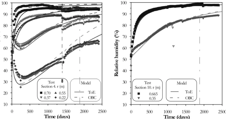
Fig. 12 – Evolution of the relative humidity. Observed versus computed values of ‘ToE’ (Thermo-osmotic Effect) and ‘OBC’ (Operational Base Case) models. a) Sections A4-B4. b) Sections A10-B10.
A series of analyses including the thermo-osmosis effect were carried out to explore the possibility that this coupled process may help the explanation of themock-up test observations. It is necessary to mention the lack of experimental data for FEBEX bentonite concerning the phenomenological coefficient associated to the thermo-osmotic flow. The thermo-thermo-osmotic constant adopted in the analysis is 2.73×10⁻¹³m2/K/s and falls in the range of possible values found in the literature for low perme-ability materials (Soler 1999, Djeran 1993).
Figure 12 shows, with solid lines, the results ob-tained considering the Thermo-osmotic Effects (ToE) for the two reference sections; the dash lines correspond to the ‘OBC’ case. In the hot section, a better agreement with the observations can be noted specially in zones
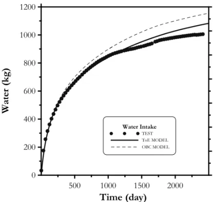
close to the heater. As expected, the responses of Sec-tions A10 and B10 do not change under this hypoth-esis. Finally, Figure 13 presents the evolution of the water intake. It has been shown that, in general term, the inclusion of the thermo-osmotic flows in the analysis improves the performance of the model. However, the results presented should be considered only as an exer-cise performed with the aim of investigating the hypo-thetical response of the barrier under these assumptions, until more experimental evidence on the phenomenon becomes available.
CONCLUSIONS
Fig. 13 – Evolution of the water intake. Observed versus computed values of ‘ToE’ (Thermo-osmotic Effect) and ‘OBC’ (Operational Base Case) models.
carried out under controlled thermo-hydra-mechanical conditions at CIEMAT laboratory (Madrid, Spain). This research has been performed in the context of the Eu-ropean projects FEBEX and NF-PRO. The main com-ponents of THM formulation adopted for the numerical analysis of this experiment have also been introduced. The comprehensive laboratory works carried out in the context of the FEBEX project have been used to identify the main parameters of the THM constitutive laws re-quired for the modelling. An initial model, coded as OBC, was developed at the beginning of the heating and hydration of the mock-up test. Good model pre-dictions have been obtained for, approximately, the first three years of the experiment. However, the results ob-tained are not totally satisfactory because the modelling over-predicts the hydration rate of the barrier at advanced stages of the hydration. A tendency to keep a constant and very low rate of the water intake and nearly con-stant values of the main variables (relative humidity and stresses) at different radii of the barrier can be observed in all the sections of the test, with a more marked trend in the cross-sections that involve heater. Changes in the constitutive law or its parameters could not reproduce accurately the test evolution.
The main problems observed in the modelling of
ACKNOWLEDGMENTS
This research work has been carried out in the context of the FEBEX and NF-PRO Projects, financed by ENRESA (Spanish National Agency for Waste Man-agement) and the European Commission (EC Contracts FI4W-CT95-006 and FIKW-CT-2000-00016 and FI6W-CT-2003-02389). Dr. P.L. Martín and co-workers (at CIEMAT) supported the design and maintenance of themock-up test. Dr. A Lloret (UPC), Dr. MV Villar (CIEMAT) and co-workers (at UPC and CIEMAT) per-formed the laboratory work.
RESUMO
O armazenamento de rejeitos altamente radioativos é ainda um problema em aberto na área de engenharia nuclear sendo os sítios geológicos ainda a opção mais favorável e natural-mente aquela que demanda maior conhecimento na área de geomecânica. A maioria dos projetos conceituais de armaze-namento do lixo nuclear objetiva a alocação de cilindros que contêm os rejeitos em poços verticais ou horizontais. O espaço vazio que circunda os cilindros é preenchido por uma barreira de engenharia na maioria dos casos composta por uma argila expansiva. Na barreira e na vizinhança fenômenos significa-tivos de acoplamento termo-hidro-mecânico(THM) tomam lu-gar e interagem entre si de maneira bastante complexa. Um bom entendimento dos tópicos em acoplamento THM é por-tanto necessário para assegurar a boa performance das barreiras de engenharia. As condições da bentonita em uma barreira de engenharia para o armazenamento do lixo nuclear foram simuladas em um teste de calor experimental nas premissas do CIEMAT em Madrid. A evolução das variáveis que go-vernam o acoplamento termo-hidro-mecânico neste teste são analisadas neste artigo utilizando uma formulação totalmente acoplada juntamente com o código computacional de elemen-tos finielemen-tos. Ênfase especial é dada ao estudo do escoamento termo-osmótico na hidratação da barreira argilosa no estágio avançado do experimento.
Palavras-chave:argilas expansivas, teste de calor, armazena-mento do lixo nuclear, análise do acoplaarmazena-mento termo-hidro-mecânico.
REFERENCES
ALONSO E, GENS AAND JOSAA. 1990. A constitutive model for partially saturated soils. Géotechnique 40(3): 405–430.
BEARJ. 1972. Dynamics of fluids in porous media. Dover Edit, 164 p.
CIEMAT REPORT. 2002. 19thData Report Mock-Up test. Informe 70-IMA-L-9-96. CIEMAT. Madrid.
CODE_BRIGHT USER’SMANUAL. 2008. UPC Geome-chanical Group.
DE MARSILY G. 1986. Quantitative Hydrogeology. Aca-demic Press, Inc. ISBN 0-12-208916-2, 440 p.
DJERAN I. 1993. Étude des duffusions thermique et hy-draulique dans una argile soumise á un champ de tempéra-ture. Sciences et techniques nucléaires rapport. Commis-sion des Communautés européennes, ISBN 1018–5593. ENRESA. 1995. Almacenamiento geológico profundo de
residuos radiactivos de alta actividad (AGP). Diseños conceptuales genéricos. Publicación Técnica ENRESA 11/95, Madrid, 105 p.
ENRESA. 1998. FEBEX. Bentonite: origin, properties and fabrication of blocks. Publicación Técnica ENRESA 4/98, Madrid, 146 p.
ENRESA. 2000. FEBEX Project. Full-scale engineered barriers experiment for a deep geological repository for high level radioactive waste in crystalline host rock. Final Report. Publicación Técnica ENRESA 1/2000, Madrid, 354 p.
ENRESA. 2006. Full-scale Engineered Barriers Experiment. Updated Final Report 1994-2004. Publicación Técnica ENRESA 05-0/2006, Madrid, 590 p.
GENS A. 1995. Constitutive Laws. In Modern issues in non-saturated soils. In: GENS A, JOUANNA P AND SCHREFLERB (Eds), Wien New York: Springer-Verlag, p. 129–158.
GENSA, GARCIAMOLINAA, OLIVELLA S, ALONSOEE ANDHUERTASF. 1998. Analysis of a full scale in-situ test simulating repository conditions. Int Jnl Numer Anal Meth. Geomech 22: 515–548.
LLORETA, VILLARMVANDPINTADOX. 2002. Ensayos THM: Informe de síntesis. Internal Report CIEMAT/ DIAE/54520/1/02. FEBEX Report 70-UPC-M-0-04, Barcelona, 98 p.
LLORETA, VILLARMV, SÁNCHEZM, GENSA, PINTADO X AND ALONSO E. 2003. Mechanical behaviour of heavily compacted bentonite under high suction changes. Géotechnique 53: 27–40
MISSANATET AL. 2004. FEBEX II Project: THG Labora-tory experiments. Publicación Técnica ENRESA 09/2004, Madrid, 137 p.
MITCHELLJ. 1993. Fundamentals of soil behaviour. 2nded., J Wiley & Sons, 437 p.
OLIVELLAS. 1995. Non-isothermal multiphase flow of brine and gas through saline media. PhD Thesis. Universitat Politècnica de Catalunya (UPC). Barcelona.
OLIVELLA SANDGENSA. 2000. Vapour transport in low permeability unsaturated soils with capillary effects. Transport porous media 40: 219–241.
OLIVELLA S, GENS A, CARRERA J AND ALONSO EE. 1994. Nonisothermal multiphase flow of brine and gas through saline media. Transport Porous Media 15: 271– 293.
OLIVELLA S, GENS A, CARRERA J AND ALONSO EE. 1996. Numerical formulation for a simulator (CODE-BRIGHT) for the coupled analysis of saline media. Eng Computations 13(7): 87–112.
PINTADOX, LEDESMAAANDLLORETA. 2002. Backanal-ysis of thermohydraulic bentonite properties from labora-tory tests. Eng Geol 64: 91–115.
SÁNCHEZM. 2004. Thermo-hydro-mechanical coupled anal-ysis in low permeability media. PhD Thesis. Universitat Politècnica de Catalunya (UPC), Barcelona, 281 p. SÁNCHEZM ANDGENS A. 2001. Report on THM
mod-elling results. FEBEX II. UPC Geomechanical Group. ENRESA Report: 70-UPC-L-5-010.
SÁNCHEZ M AND GENS A. 2006. FEBEX Project final report. Final report on thermo-hydro-mechanical mod-elling. Publicación Técnica ENRESA 05-2/2006, Madrid, 163 p.
SÁNCHEZM, GENSA, GUIMARÃESLANDOLIVELLAS. 2005. A double structure generalized plasticity model for expansive materials. Int Jnl Num Anal Meth In Geom 29: 751–787.
SOLER J. 1999. Coupled transport phenomena in the opal-inus clay: implications for radionuclide transport. Paul Scherrer Institut No. 99-07- ISSN 1019–0643.
VAN GENUCHTEN MT. 1978. Calculating the unsaturated hydraulic conductivity with a new closed-form analytical model. Water Resour Res 37(11): 21–28.
VILLARMV. 2002. Thermo-hydro-mechanical characterisa-tion of a bentonite from Cabo de Gata. A study applied to the use of bentonite as sealing material in high level radioactive waste repositories. Publicación Técnica EN-RESA 01/2002, Madrid, 258 p.
APPENDIX
TheB B Myield surface(FLC)is given by (17) and the
plastic potential(G)is expressed as
G= α3J2 −
g(θ )
g(−30◦) 2
M2(p+ps)(p0−p)=0 (A1)
whereαis determined according to Alonso et al. (1990).
The dependence of the tensile strength on suction and temperature is given by
ps =ks e−ρ1T (A2)
wherekandρ are model parameters. The dependence
of p0on suction is given by
p0=pc
p∗
0T pc
λ(0)−κ λ(s)−κ
(A3a)
p0T∗ = p0∗+2(α11T+α31T|1T|) (A3b)
where pc is a reference stress, α1 andα3 are models parameters. α(s) is the compressibility parameter for
changes in net mean stress for virgin states of the soil. This parameter depends on suction according to
λ(s)=λ(0)r+(1−r)exp(−ζs) (A4)
where r is a parameter that defines the minimum soil compressibility (at infinite suction), andζ is a parameter