José Luís Cardoso da Silva
Março de 2012
UMinho|20
12
Rapid Prototyping of Ubiquitous
Computing Environments
Rapid Pro
to
typing of Ubiquitous
Computing Environments
José Luís Car
doso da Silva
Escola de Engenharia
Tese de Doutoramento em Informática
das Universidades de Minho, Aveiro e do Porto
Março de 2012
Trabalho realizado sob a orientação do
Professor Doutor José Francisco Creissac
Freitas de Campos
e do
Professor Doutor Michael Douglas Harrison
José Luís Cardoso da Silva
Rapid Prototyping of Ubiquitous
Computing Environments
Escola de Engenharia
Universidade do Minho, ___/___/______
v
Acknowledgments
Many people contributed to this thesis. First of all, I would like to thank my supervisors José
Creissac Campos and Michael Harrison for their expert guidance, strong support and
con-tinuous encouragement and whose human side I highly appreciated. Sincerely, I feel so lucky
to have you as supervisors! This period was an experience which has helped me grow up not
only professionally but also as a person and resulted in this thesis that would have not been
possible without both of you.
During these last four years, I had the pleasure of collaborating with many people. I
would like to thank all Newcastle University members that made my stay in Newcastle more
pleasant. I also want to thank friends who I have made in Newcastle, in particular, Sergio
Moya, Zhao Ran, Chu Chien, Yousef Abushnak, Abdulrahman, Fahren Bukhari, Paulo and
members of The Globe which I had the pleasure to meet and which contributed for a
agree-able period of my life. Finally, a cherished thank you to Mary Holland for all help and
pa-tience.
Many thanks are due to the members of the Creativity Machine Environment Lab, Aware
Home Research Initiative Group and Ubiquitous Computing Research Group of the Georgia
Technology Institute (USA) for their feedback and suggestions. I would like to specially
thank Mario Romero for having provided the Google Sketchup model of the Aware Home and
Gregory Abowd for having hosted me.
Parts of my thesis were published in conferences. I would like to thank my co-authors, all
the anonymous reviewers and all people who provided important remarks, comments and
suggestions. Also thank you for all members and participants of the APEX project for their
contributions.
I would like to thank the Fundação para a Ciência e Tecnologia for their financial
sup-port.
All my colleagues and friends, especially João Carlos, Helder and Rafael and, my cousins
José Manuel and César who are so important in my life, thank you!
My last words go to my family who always support me, in particular, Susana for her
vi
My brother is my model! A very special thank you to João Carlos for being my biggest
friend...
Rodrigo is the happiness of my family! Children are a sun in this world...
Finally, a very special thank you to Elisabete for all her continuous encouragement,
vii
This work is funded by the ERDF through the Programme COMPETE and by the
Portu-guese Government through FCT - Foundation for Science and Technology, project ref.
PTDC/EIA-EIA/116069/2009 and by FCT, under the grant with reference
ix
Environments
Abstract
Ubiquitous computing raises new usability challenges that cut across design and
develop-ment. We are particularly interested in environments enhanced with sensors, public displays
and personal devices. How can prototypes be used to explore the users' mobility and
interac-tion, both explicitly and implicitly, to access services within these environments? Because of
the potential cost of development and design failure, these systems must be explored using
early assessment techniques and versions of the systems that could disrupt if deployed in the
target environment. These techniques are required to evaluate alternative solutions before
making the decision to deploy the system on location. This is crucial for a successful
devel-opment, that anticipates potential user problems, and reduces the cost of redesign.
This thesis reports on the development of a framework for the rapid prototyping and
analysis of ubiquitous computing environments that facilitates the evaluation of design
alter-natives. It describes APEX, a framework that brings together an existing 3D Application
Server with a modelling tool. APEX-based prototypes enable users to navigate a virtual world
simulation of the envisaged ubiquitous environment. By this means users can experience
many of the features of the proposed design. Prototypes and their simulations are generated in
the framework to help the developer understand how the user might experience the system.
These are supported through three different layers: a simulation layer (using a 3D Application
Server); a modelling layer (using a modelling tool) and a physical layer (using external
de-vices and real users). APEX allows the developer to move between these layers to evaluate
different features. It supports exploration of user experience through observation of how
us-ers might behave with the system as well as enabling exhaustive analysis based on models.
The models support checking of properties based on patterns. These patterns are based on
ones that have been used successfully in interactive system analysis in other contexts. They
help the analyst to generate and verify relevant properties. Where these properties fail then
xi
Ubíqua
Resumo
A computação ubíqua levanta novos desafios de usabilidade transversais ao seu
desenvolvi-mento e design. Estamos particularmente interessados em ambientes enriquecidos com
senso-res, ecrãs públicos e dispositivos pessoais e em saber como podem ser utilizados protótipos
na exploração da mobilidade e interação, implícita e explicita, dos utilizadores de forma a
acederem a serviços desses ambientes. Devido às potenciais falhas do design proposto e aos
elevados custos associados ao seu desenvolvimento, as características destes sistemas devem
ser exploradas utilizando versões preliminares dos mesmos dado que estes podem vir a falhar
quando implementados no destino, tornando a sua utilização inaceitável. Essas técnicas são
necessárias por forma a avaliar soluções alternativas antes de decidir implementar o sistema
fisicamente. Isto é crucial para um desenvolvimento com sucesso que antecipe potencias
pro-blemas do utilizador e reduza os custos de redesign.
Esta tese descreve o desenvolvimento de uma ferramenta para a prototipagem rápida e
análise de ambientes de computação ubíqua como suporte à avaliação de designs alternativos.
É apresentado a APEX, uma plataforma que junta um servidor de aplicações 3D com uma
ferramenta de modelação. Os protótipos baseados na APEX permitem aos seus utilizadores
finais navegarem numa simulação 3D do ambiente ubíquo projetado. Desta forma muitas das
características do design proposto podem ser experienciadas pelos utilizadores. Os protótipos
e respetivas simulações são gerados na plataforma para ajudar os designers/developers a
entender como é que os utilizadores podem experienciar o sistema. Os protótipos são
supor-tadas através de três camadas: a camada de simulação (utilizando um servidor de aplicações
3D); a camada de modelação (utilizando uma ferramenta de modelação) e uma camada física
(utilizando dispositivos externos e utilizadores reais). A plataforma possibilita aos designers/
developers moverem-se entre estas camadas de forma a avaliar diferentes características do
sistema, desde a experiencia do utilizador até ao seu comportamento através de uma analise
exaustiva do sistema ubíquo baseada em modelos. Os modelos suportam a verificação de
xii
sugere um cenário de falha que fornece uma ajuda importante no redesign do sistema.
Palavras-chave:
Computação Ubíqua e Ciente do Contexto, Análise, Modelação, Prototipagem, Ambientes
xiii
The work described in this thesis resulted in the publication and presentation of papers in
national and international peer-reviewed conferences:
1. J. L. Silva, J. C. Campos, and M. D. Harrison, “An infrastructure for experience
centered agile prototyping of ambient intelligence,” in Proceedings of the 1st ACM SIGCHI symposium on Engineering interactive computing systems, 2009,
pages 79–84. [1]
2. J. L. Silva, Ó. Ribeiro, J. Fernandes, J. Campos, and M. Harrison, “The APEX
framework: prototyping of ubiquitous environments based on Petri nets,” in
Hu-man-Centred Software Engineering. Lecture Notes in Computer Science.
Springer, 2010, vol. 6409, pages 6–21. [2]
3. J. L. Silva, Ó. R. Ribeiro, J. M. Fernandes, J. C. Campos, and M. D. Harrison,
“Prototipagem rápida de ambientes ubíquos, ”in 4a. Conferência Nacional em Interacção Humano-Computador (Interacção 2010), O. Mealha, J. Madeira, D.
Tércio and B.S. Santos editors. 2010, pages 121--128, GPCG. [3]
4. J. L. Silva, J. C. Campos, and M. D. Harrison, "Formal analysis of Ubiquitous
Computing environments through the APEX framework," in Proceedings of the
4th ACM SIGCHI symposium on Engineering interactive computing systems,
2012. (Accepted)
In all cases, I have presented only those aspects of the work which are directly attributed
xv
1 Introduction ... 1
1.1 Motivation ... 1
1.2 Objectives ... 4
1.3 Research Questions ... 4
1.4 Thesis Overview ... 5
2 Background ... 7
2.1 Prototyping Approaches... 7
2.2 Modelling Approaches ... 11
2.2.1 Modelling approaches comparison ... 12
2.2.2 Coloured Petri nets (CPNs or CP-nets) ... 21
2.3 Virtual Worlds' Simulation ... 24
2.3.1 3D application servers ... 25
2.3.2 3D game engines ... 28
2.4 Analysis... 29
2.5 Conclusions ... 31
3 The Proposed Approach ... 33
3.1 APEX Framework ... 33
3.1.1 Architecture ... 33
3.1.2 Multi-layer approach ... 41
3.1.3 Support for design ... 42
3.2 Alternative Modelling Approaches ... 44
3.2.1 User-centred approach... 47
3.2.2 Sensor-centred approach ... 53
3.3 Conclusions ... 55
4 The Modelling Approach ... 57
xvi
4.2.2 Modeller's tasks ... 63
4.2.3 Modelling environment's devices ... 64
4.3 Modelling and Use of Programmed Avatars ... 65
4.4 Conclusions ... 66
5 Prototyping Experience Alternatives ... 69
5.1 Alternative User's Experiences ... 70
5.1.1 Second Life viewer ... 70
5.1.2 Support for importing virtual objects ... 71
5.1.3 Supporting 3D visualization ... 73
5.1.4 Supporting multi displays systems ... 74
5.2 Virtual Environment Creation... 76
5.3 Conclusions ... 77
6 Ubiquitous Environments Analysis ... 79
6.1 Approach ... 80
6.1.1 Tool support ... 81
6.1.2 Patterns ... 82
6.2 Setting Up the Analysis ... 83
6.2.1 Model conversion ... 83
6.2.2 APEXi tool - scenario selection and small colour sets initialization ... 86
6.2.3 Reachability graph and analysis ... 94
6.3 Property Specification Patterns for Ubicomp Environments ... 101
6.3.1 The consistency pattern ... 102
6.3.2 The feedback pattern ... 103
6.3.3 The reachability pattern ... 105
6.3.4 The precedence pattern... 106
6.3.5 The completeness pattern ... 107
6.3.6 The reversibility pattern ... 108
xvii
6.4 Alternative Analysis... 112
6.5 Programmed Avatars ... 113
6.6 Conclusions ... 114
7 Examples ... 117
7.1 Smart Library ... 117
7.1.1 The model ... 118
7.1.2 Instantiating property templates ... 121
7.1.3 Checking the model using the SS tool ... 123
7.1.4 The prototype ... 128
7.2 Aware Home ... 129
7.2.1 The model ... 130
7.2.2 Instantiating property templates ... 133
7.2.3 Checking the model using the SS tool ... 134
7.2.4 Checking non-functional properties ... 138
7.2.5 The prototype ... 140
7.3 Serious Games Development ... 141
7.4 Conclusions ... 143
8 Evaluation of the Prototyping Approach... 147
8.1 Example ... 147
8.2 Relevant User Study Techniques ... 148
8.3 Process and Questionnaire ... 150
8.4 Results ... 151
8.5 Conclusions ... 152
9 Conclusions ... 153
9.1 Answers to Research Questions ... 153
xviii
9.5 Future Work ... 157
Bibliography ... 159
Appendix A: CPN Base Model ... 167
Appendix B: CPN Analysis Model ... 171
Appendix C: Evaluation Questionnaire ... 173
Appendix D: Exercises Proposed During the Evaluation ... 175
xix
2D Two-Dimensional
3D Three-Dimensional
APEX rApid/Agile Prototyping for user EXperience
API Application Programming Interface
CAVE Cave Automatic Virtual Environment
CPN Coloured Petri Nets
CSP Communicating Sequential Processes
CTL Computational Tree Logic
DLL Dynamic-Link Library
FCT Fundação para a Ciência e a Tecnologia (Foundation for Science and Technology)
ICO Interactive Cooperative Objects
GPS Global Positioning System
GUI Graphics User Interface
HCI Human-Computer Interaction
HyNets Hybrid high-level Nets
LAN Local Area Network
LSL Linden Scripting Language
OSG OpenSceneGraph
OSMP Open Source Metaverse Project
PDA Personal Digital Assistant
RFID Radio-Frequency IDentification
UBICOMP UBIquitous COMPuting
UML Unified Modelling Language
xx
xxi
FIGURE 2.1:INFORMAL PROPOSED APPROACH ... 11
FIGURE 2.2:ASUR++ MODEL (USER ARRIVING AT AN ENTRY GATE) ... 13
FIGURE 2.3:HYNETS MODEL (USER ARRIVING AT AN ENTRY GATE) ... 15
FIGURE 2.4:FLOWNETS MODEL (USER ARRIVING AT AN ENTRY GATE) ... 16
FIGURE 2.5:CPN GRAPHICAL SYNTAX ... 22
FIGURE 2.6:CPN SIMULATION ... 24
FIGURE 3.1:APEX ARCHITECTURE ... 34
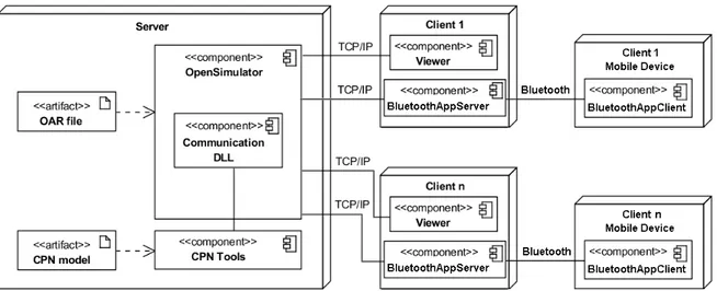
FIGURE 3.2:PHYSICAL ARCHITECTURE OF THE APEX FRAMEWORK ... 38
FIGURE 3.3:BLUETOOTH APPLICATION CLIENT INSTALLED IN A SMART PHONE ... 38
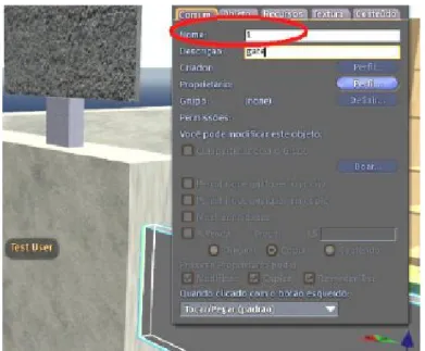
FIGURE 3.4:OBJECT' IDENTIFIER ACCESSIBLE IN THE VIEWER PANEL ... 40
FIGURE 3.5:OBJECT MOVEMENT LSL SCRIPT ... 43
FIGURE 3.6:THE PROCESS ... 44
FIGURE 3.7:ON/OFF DEVICE ALTERNATIVE MODELS.1- ALL SEMANTIC IN THE TOKENS,2- ALL SEMANTIC IN THE STRUCTURE ... 45
FIGURE 3.8:USER-CENTRED SMART LIBRARY MODULE ... 48
FIGURE 3.9:USER-CENTRED SCREEN MODULE ... 48
FIGURE 3.10:GENERAL EARLY INITIALIZATION MODULE ... 49
FIGURE 3.11:MODULE FOR AN ENTRY GATE ... 50
FIGURE 3.12:ISARRIVINGTOGATEAREA FUNCTION ... 50
FIGURE 3.13:GENERIC MODULE FOR ACQUIRING USERS’ DATA ... 52
FIGURE 3.14:PRIORITIES OVER TRANSITIONS... 52
FIGURE 3.15:APEX SENSOR-BASED MODELLING APPROACH.PARTS: A)PRESENCE SENSOR MODEL B) LIGHT SENSOR MODEL C)MODELS DEPENDING OF SENSOR'S VALUES ... 54
FIGURE 4.1:GENERAL EARLY INITIALIZATION MODULE ... 58
FIGURE 4.2:GATE MODULE ... 60
FIGURE 4.3:BOOK'S LIGHT MODULE ... 61
FIGURE 4.4:COLOUR SET DECLARATION (LIBRARY EXAMPLE) ... 64
FIGURE 4.5:PROGRAMMED AVATAR'S MODULE ... 67
xxii
ARE NOT MESHES) ... 72
FIGURE 5.4:DALE'S SLVIEWER IN ANAGLYPH STEREO MODE ... 74
FIGURE 5.5:ACTIVE STEREO - SHUTTER GLASSES BEHAVIOUR ... 74
FIGURE 5.6:ACAVE ... 75
FIGURE 5.7:DATA AND DISPLAY SYNCHRONIZATION WITH CAVESL ... 75
FIGURE 5.8:CAVESL WITH 3 CLIENTS RUNNING AT THE SAME TIME (ADAPTED FROM [82]) ... 76
FIGURE 5.9:LINKAGE OF THE ELEMENTS COMPOSING A CHAIR ... 76
FIGURE 5.10:SMART LIBRARY PROTOTYPE CREATED IN THE OPENSIMULATOR SERVER ... 77
FIGURE 5.11:MESH UPLOAD THROUGH THE PROJECT MESH VIEWER ... 78
FIGURE 6.1:REACHABILITY GRAPH ... 81
FIGURE 6.2:DATATYPEREADING NON-DETERMINISTIC MODULE ... 85
FIGURE 6.3:DATATYPEREADING DETERMINISTIC MODULE ... 85
FIGURE 6.4:APEXI TOOL CONNECTION TO THE APEXBEHAVIOURAL COMPONENT ... 87
FIGURE 6.5:APEXI INTERFACE ... 89
FIGURE 6.6:APEXI AND CPN MODEL CONNECTION MODULE ... 93
FIGURE 6.7:MODULE WHICH INITIALIZE SOME SMALL COLOUR SETS (E.G.USERSIDS,OBJIDS) ... 93
FIGURE 6.8:REACHABILITY GRAPH ... 95
FIGURE 6.9:APEXI SELECTED VALUES ... 95
FIGURE 6.10:REACHABILITY GRAPH NODE CONSULTATION ... 96
FIGURE 6.11:CPN LIGHT MODULE ... 97
FIGURE 6.12:SPECIFICATION OF ELEMENTS IN THE APEXI INTERFACE: A) ONE USER; B) ONE LIGHT; C) ONE
PRESENCE SENSOR; D) USER MOVEMENT SIMULATION; E) ONE TIME SENSOR ... 98
FIGURE 6.13:LIGHTS' ON QUERY ... 99
FIGURE 6.14:LIST OF NODES WHERE THE LIGHT IS ON ... 99
FIGURE 6.15:LIGHT TURNS OFF PROPERTY ... 99
FIGURE 6.16:INSERTING TWO PRESENCE SENSORS IN THE APEXI INTERFACE ... 100
FIGURE 6.17:CONSISTENCY/FEEDBACK PROPERTY ALGORITHM SKELETON ... 104
xxiii
F 6.20:C ... 108
FIGURE 6.21:ALGORITHM SKELETON FOR THE IDENTIFICATION OF THE NODES BEFORE AND AFTER Q ... 109
FIGURE 6.22:FUNCTION TO PROVIDE ALL NODES OF THE REACHABILITY GRAPH ... 110
FIGURE 6.23:UNIVERSALITY PROPERTY ALGORITHM SKELETON ... 111
FIGURE 6.24:EVENTUALLY PROPERTY ALGORITHM SKELETON ... 112
FIGURE 7.1:USER'S PDA BOOK DIRECTION MODULE ... 120
FIGURE 7.2:APEXI - SELECTED VALUES ... 124
FIGURE 7.3:BOOK'S LIGHT BEHAVIOUR PROPERTY (CONCRETE FEEDBACK ALGORITHM INSTANTIATION) ... 125
FIGURE 7.4:NOTIFICATION PROPERTY (CONCRETE REACHABILITY ALGORITHM INSTANTIATION) ... 127
FIGURE 7.5:BOOK'S LIGHTS SYSTEM ... 128
FIGURE 7.6:PEOPLE'S READING VIEW ... 129
FIGURE 7.7: AWARE HOME FLOOR PLAN (WITHOUT FURNITURE) WITH INSERTED SENSORS (ONE PRESENCE
SENSOR AND ONE ENVIRONMENT SENSOR PRESENT IN EACH NUMBER) ... 130
FIGURE 7.8:AWARE HOME 3D ENVIRONMENT ... 131
FIGURE 7.9:PARENTS’ ALERT SYSTEM BEHAVIOURAL MODEL ... 132
FIGURE 7.10:AIR QUALITY ALERT SYSTEM ... 132
FIGURE 7.11:PARENTS ALERTED PROPERTY (FEEDBACK) ... 136
FIGURE 7.12:PARENTS ALERTED PROPERTY (REACHABILITY) ... 137
FIGURE 7.13:PHYSICAL PROPERTY (PRESENCE SENSOR DISTANCE) ... 139
FIGURE 7.14:AWARE HOME ALERT SYSTEM USER EXPERIENCE ... 140
FIGURE 7.15:ASTHMA TRIGGER PARENT'S ALERT VIA THEIR PDA ... 141
FIGURE 7.16:TRIGGERHUNTER GAME SNAPSHOT (ADAPTED FROM [95]) ... 142
FIGURE 7.17:TRIGGERHUNTER GAME ASTHMA TRIGGER MANAGEMENT ... 143
FIGURE 7.18:GAME MODULE ... 144
FIGURE 7.19:TRIGGER HUNTER GAME USING APEX- ASTHMA TRIGGER DISCOVERED ... 145
FIGURE 7.20:APEX- ITERATIVE CYCLE OF PROTOTYPING (DESIGN, TEST AND ANALYSIS) ... 146
FIGURE 9.1:APEX FIELDS ... 155
FIGURE A.0.1:CPN BASE INITIALIZATION MODULE ... 167
xxiv
FIGURE B.0.1:CPN ANALYSIS DYNAMIC OBJECTS UPDATE MODULE ... 171
FIGURE B.0.2:CPN ANALYSIS LIGHT SENSORS UPDATE MODULE ... 172
FIGURE B.0.3:CPN ANALYSIS TIME SENSORS UPDATE MODULE ... 172
FIGURE C.0.1:APEX QUESTIONNAIRE - FIRST PART ... 173
FIGURE C.0.2:APEX QUESTIONNAIRE - SECOND PART ... 174
FIGURE E.0.1:INSTALLATION STEPS DIAGRAM ... 178
FIGURE E.0.2:SENSOR'S ATTRIBUTES ... 180
FIGURE E.0.3:DYNAMIC OBJECT SCRIPT ASSOCIATION ... 181
xxv
TABLE 2.1:PROTOTYPING APPROACHES COMPARISON ... 10
TABLE 2.2:MODELLING APPROACHES COMPARISON ... 19
1
Chapter 1
Introduction
1
Introduction
Ubiquitous computing (ubicomp) was defined in 1988 by Mark Weiser as “machines that fit
the human environment instead of forcing humans to enter theirs” [4]. Ubicomp is an
evolu-tion of the desktop paradigm of human-computer interacevolu-tion (HCI). In ubicomp
environ-ments, computing is inserted into our environments. This means that these environments
pos-sibly do not require active attention because the information is transmitted automatically.
These environments pose new challenges for designers and developers mainly because of the
wide range of computer science fields involved: distributed computing, sensor networks,
mo-bile computing, HCI and artificial intelligence. In recent years ubicomp systems have become
more widespread. Partly as a consequence of device availability the reality of a ubicomp
world is becoming more imminent. Ubicomp technologies include smart phones that
incorpo-rate many types of sensors, RFID tags and GPS, as well as interactive whiteboards which are
used to populate ubicomp environments. This thesis is concerned with the rapid prototyping
of ubicomp environments.
The research questions identified during the initial phase of this thesis, and the proposed
solutions, led to the proposal of a project1 which was funded by the FCT (Fundação para a
Ciência e Tecnologia).
1.1
Motivation
This thesis focuses on ubicomp designed to enhance physical environments by using “spaces”
augmented with sensors, dynamic objects including public displays, and personal devices.
Dynamic objects react to interactions and to context changes as well as providing services to
1
2
users in the environment. Of particular interest in these systems is the way that the user
inter-acts with the environment, as a result of both explicit interaction with the system and implicit
interactions that arise through changes of context. Here, context could include location, or the
steps that have to be taken by a user to achieve some goal (for example check-in, baggage
screening, passport control, boarding card scanning).
The experience of checking into an airport can be improved by providing information to
travellers when and where they need it. Frustrating delays can be removed through the
appro-priate use of personalised information. The experience of using a library can be improved by
providing personal and clear information about the location of the shelf in a large library
where the required book is located. Experience is difficult to specify as a clear and precise
requirement that can be demonstrated of a system. It is difficult to measure and to obtain
early feedback about whether a design will have the required effect to produce a given
ex-perience.
Technologically enhanced environments have the potential to transform sterile built
envi-ronments into places in which people can be in harmony with the environment and its
pur-pose if appropriately designed. Ubiquitous computing pur-poses new challenges for designers and
developers of interactive systems. Early prototyping and simulation of ubicomp environments
is likely to result in reducing development cost by allowing the assessment of alternatives
before expensive development. Because these systems immerse their users, the effect they
have on the users' experience is an important element contributing to the success of a design.
Experience becomes an important characteristic in addition to more traditional notions of
usability.
Testing ubicomp systems in real environments suggests the quality issues in ubicomp
en-vironments include more than just usability [5]. Essential also is the concern of UX (user
ex-perience) [6]. Being able to evaluate and analyse ubiquitous environments as well as
provid-ing user experience early, before deployment, is the topic of concern here. The work is based
on the presumption that prototypes can be used to explore the impact of a design on users as
they move and interact, accessing services within these environments. Prototypes are also
used to analyse ubiquitous environment behaviours. To avoid unnecessary development cost,
early designs and solutions are explored in this proposal through model-based prototypes
3
models and binds them to a 3D simulation is the subject of this thesis. The APEX framework
supports prototyping and simulation by providing:
rigorous models of the system behaviour including sensors, dynamic objects and
mo-bile display devices;
a 3D simulation of the environment created in a virtual world;
the animation of the 3D simulation based on behavioural models that are also
devel-oped within the framework;
a means of connecting external (physical) devices to the virtual world via Bluetooth.
Users can interact either by manipulating physical handheld devices or by controlling
avatars located in the virtual world;
analysis support through the models.
Currently there are no techniques that can be used to analyse specifications against
dif-ferent notions of experience (for a discussion, see [7]). The facets of APEX provide three
layers of behavioural representation moving from the abstract to the concrete:
a modelling layer expressed in terms of formal models;
a simulation layer programmed or encoded in the 3D simulation;
a physical layer where external devices are connected to the simulation.
Each layer supports a specific type of evaluation:
analysis of the model i.e., systematic exploration of the environments behaviour,
through analysis of the models (in the modelling layer);
observation of virtual objects' behaviour, and user reaction to them, within a virtual
world (in the simulation layer);
observation of real objects (for example, actual smart phones) connected to the virtual
world, and users’ reaction to them (in the physical layer).
Each layer captures a different view on users. Evaluation can be carried out by observing
actual behaviour of users within the environment, interacting with the simulation at the
physical layer. Alternatively, users can be represented and simulated by avatars that are user
representations in the 3D simulation. Finally, user behaviour can also be captured abstractly
as tokens within the model. A goal of using a formal model is that a formal analysis of the
design can be used to complement the exploration of the design via actual users. While the
4
possible interactions between the numerous components of the ubicomp environment. Hence
an exhaustive analysis of the environment’s alternative behaviours is desirable.
1.2
Objectives
APEX is designed to satisfy three goals. The first is that it should enable the rapid
develop-ment of prototypes. A software tool is required that facilitates the developdevelop-ment of prototypes,
while simultaneously providing the hooks for the target system. The second goal is that a 3D
environment can be used to construct simulations that can be explored realistically by users.
3D Application Servers, such as Second Life™2
, Open Wonderland3 or OpenSimulator4,
pro-vide a fast track to developing virtual worlds. An alternative would be game engines (e.g.
OpenScenceGraph5). The third goal is an approach to modelling ubicomp environments
aim-ing to create some of the texture of the environment for evaluation purposes. We are
inter-ested in creating prototypes of ubiquitous environments from models of envisaged systems. A
benefit of this approach is the integration of the modelling approach with analytical
ap-proaches, to provide leverage relating to properties of ubiquitous environments that are
rele-vant to their use. The satisfaction of these goals will be demonstrated throughout this thesis.
The development of a framework that assists developers and designers in the efficient
development of ubicomp environments is the main objective of this work. The costs involved
in the development of these systems for them to be ready for user testing can be very high,
consequently there is an opportunity to create a framework which will reduce these costs
while providing a way of experiencing the system before physical deployment. Being able to
guarantee specific properties of the system and providing analysis and reasoning methods are
also features which help developers in the rapid and effective prototyping of these systems.
1.3
Research Questions
The overarching goal therefore is to investigate whether:
2
Second Life: http://secondlife.com/ (last accessed: 15 November 2011)
3
Open Wonderland: http://openwonderland.org/ (last accessed: 15 November 2011)
4
Opensimulator: http://opensimulator.org/ (last accessed: 15 November 2011)
5
5
The ubicomp environment development process can be made easier thereby reducing
costs, providing early experience and automated analysis support.
This goal raises a number of consequent issues that needs to be addressed. Firstly an
aquate ubicomp environment representation model should be identified which facilitates
de-velopment. Secondly, these environments should provide experience during the early phases
of development. Thirdly, they should be able to be analysed through automated mechanisms
enabling the verification of properties. Having this in mind the following primary research
questions needs to be answered:
Question 1: can a formal model represent ubicomp environments?
Question 2: can ubicomp environments prototypes address features with the potential to assess user experience without physical deployment?
Question 3: can ubicomp environment be analysed in the early phase of development providing evaluation results at different levels?
They will be addressed throughout the thesis.
1.4
Thesis Overview
As stated the main contribution of this thesis is to provide an approach for the rapid
prototyp-ing of ubicomp environments. A framework has been developed, providprototyp-ing early experience
of the prototyped environment as well as analysis support. The approach will be presented
and described via some examples. Finally the results of an evaluation of the tool with
poten-tial developers will be outlined. The dissertation document is structured as follows:
Chapter 2 - Background: examines the current state of the art and identifies current needs regarding rapid ubicomp prototyping with a particular emphasis on prototyping,
modelling and simulation approaches;
Chapter 3 - The Proposed Approach: presents the approach used for the rapid
proto-typing of ubicomp environments. The architecture and features of the developed
framework are presented. Additionally, two alternative approaches for modelling are
outlined. A more thorough description is provided in Chapter 4;
Chapter 4 - The Modelling Approach: presents the selected modelling approach and
guidelines to be followed in the modelling of new ubicomp environments.
6
Chapter 5 - Prototyping Experience Alternatives: presents alternative solutions that
are used to provide a more complete and immersive experience to users. Being an
es-sential component of the experience provided, the virtual environment creation
proc-ess is also presented;
Chapter 6 - Ubiquitous Environments Analysis: introduces the process to accomplish analysis of ubicomp environments prototypes through APEX. The process is based on
the use of property patterns that are described. The use of programmed avatars and
other alternative analysis approaches are also presented;
Chapter 7 - Examples: describes analysis and experience results provided by the
de-veloped framework through its application to three concrete example;
Chapter 8 - Evaluation of the Prototyping Approach: presents relevant alternative user study techniques and shows the results of the evaluation of APEX by developers
us-ing a combination of two of the stated user study techniques;
Chapter 9 - Conclusions: presents a summary of the contributions of the thesis and
discusses some of the results obtained. Finally, directions for future work are pointed
7
Chapter 2
Background
2
Background
This chapter is divided into five sections. The first introduces alternative approaches found in
the literature for the prototyping of ubicomp environments. The second section focuses on the
description of possible modelling approaches for these environments. The third section
de-scribes alternative simulation tools and the forth dede-scribes approaches for the analysis of
ubi-comp environments. The state of the art of prototyping ubiubi-comp environments and related
topics (e.g. modelling and simulation) is summarised in the last section.
2.1
Prototyping Approaches
As stated in Chapter 1 the development of ubicomp environments is a complex task that can
lead to common problems involving design, cost and the physical space in which they are
situated. Fielding such systems for testing purposes is, in many cases, not feasible (consider a
hospital or an airport). The acquisition of adequate resources (e.g. physical devices, sensors),
the deployment to its target location, and subsequent experimentation, all have expensive
associated costs. Design decisions, once committed to, can be difficult to reverse [8]. There is
a real problem with identifying and resolving subtle design issues at an early stage in the
de-sign process before too many resources have been invested and too much time elapsed.
Sev-eral approaches found in the literature are concerned with this problem as well as providing
and suggesting solutions for it. Any method that allows a system to be explored or analysed
at an early stage may indeed make a strong contribution to the field. Some of the proposed
approaches concern ubicomp prototyping. Prototypes provide designers with a way of
check-ing proposed solutions with low investment. However there is a tension between the quality
8
implementation of the final systems. Prototypes should provide results reflecting adequately
the aspects of the physical implementation of the system in location.
Prototyping ubiquitous systems (see [9] for a good overview) is mostly concerned with
the development of prototypes of isolated devices e.g. UbiWise [10], UbiREAL [11], d.tools
[12] or Topiary [13]. The systems are typically to be explored outside the context of the fully
integrated system in its proposed setting, see Abowd et al.’s paper in [14] for a useful discus-sion of this contrast. For example d.tools is used to prototype isolated devices through
inte-grated design, test and analysis. The tool provides the capability to connect physical devices
(e.g. sensors, actuators) to the developed models enabling the behaviour analysis of the
physical devices through their respective model specifications. The framework supports the
whole cycle of prototyping of isolated devices. Topiary enables users to explore prototypes of
a context aware application in a real world setting. These prototypes often use Wizard of Oz
techniques to avoid the need for physical sensors and actual physical. These systems miss the
crucial interplay between device and environment to aid understanding of the prototyped
en-vironment [15]. Displays, devices and sensors form an integrated whole that, together with
physical characteristics of the environment, contributes to the texture of the resulting system.
In the context of healthcare applications, within which one of our examples fits, Kang et al.
[16] propose a systematic design tool for context aware systems in a smart home. The context
aware framework developed using their tool works as a middleware between sensors and
service entities. Their focus is not the prototyping of ubiquitous environments but rather the
prototyping of middleware to solve the interoperability problem among sensor makers and
healthcare service providers.
3DSim [17], UbiWorld [18], the work of O’Neill et al. [19, 20], and VARU [21] develop
simulations of actual environments. While 3DSim and UbiWorld use programming languages
to build prototypes, the benefit of the work of O'Neill et al. is that modelling can be combined
with simulations. They combine models with a 3D simulation to prototype ubiquitous
envi-ronments. Vanacken et al. [22] also adopt a model based approach. However their focus is on
the detail of the interaction within the 3D virtual environment and not in the development of
ubicomp environments. In VARU a prototype of a tangible space, combining virtual and
augmented reality, can be used to explore ubiquitous computing. A rendering game engine
based on OpenSceneGraph6 is used to achieve this.
6
9
Activity Studio [23] is a tool for prototyping and in-situ testing of ubicomp application
prototypes. It provides support for testing low-cost ubicomp prototypes in experimentally
relevant environments over extended periods. Several users can explore the prototype over
time and information, either from real sensors or reported by users can be provided to the
prototype. The analysis is produced as a result of monitoring user activities. The approach
lowers the cost of in-situ testing and deploying of ubicomp prototypes. The work of Sohn et
al. (ICap [24]) is also relevant here, it assists developers in the informal prototyping and
test-ing of context-aware applications by providtest-ing a tool that allow users to quickly define input
and output devices and involves rule based conditions prior to the development of an
execu-table system. Momento [25] is a tool for early-stage prototyping and situated experimentation
and evaluation of ubicomp applications but does not provide exhaustive analysis support. It is
focussed on ubicomp applications experimentation by experience sampling or other
qualita-tive data rather than using a virtual environment.
A further approach, the work of Pushpendra Singh et al., involves the rapid prototyping
and evaluation of intelligent environments using immersive video [26]. The approach
pro-vides some advantages by removing the need to develop (virtual) environments. However
important features that will provide an adequate infrastructure for prototyping are currently
listed as future work. The major omission is that it does not provide users with capabilities to
interact with the environment. Unfortunately, publications that demonstrate achievement of
these plans cannot be found in the literature.
Different types of prototyping are possible, for example:
1. a single device isolated from its context of use;
2. an application/device and it context of use;
3. the environment as enriched by devices.
While several approaches, aiming at ubiquitous computing prototyping, were identified
above, they are mostly focused on helping ubiquitous system designers to identify unwanted
behaviour in their system, and to support informed decision making in an iterative design
cycle. Some of these approaches focus on ubicomp prototyping applications or isolated
de-vices and not on the prototyping of ubicomp environments as a whole. Some provide a notion
of experience but not of the whole ubicomp environment. The work of O'Neill combines 3D
simulation with models but their focus is to identify occurrences of unwanted system
behav-iours. They do not provide exhaustive analysis support. Other approaches, for example
10
key features of the main solutions presented. Some of the stated solutions are not listed in the
table because they share common features of presented solutions. For example the UbiWise
solution is not listed because it has common main features with d.tools.
UbiREAL d.tools Topiary 3DSim UbiWorld VARU Activity
Studio
Momento
Applications/isolated
devices prototyping
yes yes yes yes yes yes yes yes
Unwanted behaviour
identification
yes yes yes yes yes yes yes yes
Ubicomp
environ-ments prototyping
no no no yes yes yes no no
Provide user
experi-ence
no yes yes yes yes yes yes no
Formal exhaustive
analysis support
no no no no no no no no
Whole cycle of
proto-typing support
no yes yes no no no no no
Table 2.1: Prototyping approaches comparison
There is an absence of an approach that focuses on the experience that users will have of
the design of the whole ubicomp environment, and which supports a formal and exhaustive
analysis. An approach satisfying these requirements will provide a distinct advance over the
state of the art. To convincingly demonstrate its utility, when compared with the existing
frameworks, the desired approach should provide:
support for the design of the ubicomp environment and to explore alternatives, with a
particular emphasis on how users will experience it (including first view experience);
support for analysis either by simulation (similar to program execution) or by more
formal analysis;
a multilayered development approach similar to d.tools and VARU approaches;
support for the whole cycle of prototyping (design, experience, test and analysis) similar to the d.tools approach;
multi-user support and collaborative features (e.g. speaking, chatting) enabling
11
A possible approach, satisfying these requirements, should combine a simulation which
will provide users with a way of experiencing a proposed design with a formal modelling
approach to enable systematic and exhaustive analysis.
Computer simulation has become a fundamental component in areas such as
mathemat-ics, physmathemat-ics, biology, economics and engineering. Simulations are used to estimate and
ana-lyse the behaviour of complex systems [27]. They are also used in the development processes
of many types of products (e.g. architecture, automotive industry). In particular 3D
simula-tions are used to validate a design before physical deployment on location. 3D provides a
representation that contains more features of the real world than non-3D simulations. In the
specific case of ubicomp it should be rich enough to provide users with the impression of
being in the deployed physical environment. On the one hand a 3D simulation seems a good
candidate to provide users with experience of ubicomp environments. On the other hand the
modelling approach should enable the modelling of ubicomp environments, allowing
reason-ing and providreason-ing analysis support both in the modellreason-ing and prototypreason-ing phases of the
de-velopment. The abstract idea of the proposed approach is presented in Figure 2.1.
Figure 2.1: Informal proposed approach
In the next two sections several alternatives relating to modelling and 3D simulation are
addressed. Comparisons between existing alternatives are presented. Both modelling and
simulation approaches which best satisfy the stated requirements are selected.
2.2
Modelling Approaches
Ubicomp environments involve several types of interaction and potentially provide many
services to users. Modelling techniques can capture interactions and be used to reason about
environment behaviours. We are unaware of a modelling approach specifically developed to
12
developed for mobile mixed systems that share some aspects with ubicomp environments. In
developing APEX several approaches were considered regarding the modelling of these
envi-ronments. This section presents a number of candidate modelling approaches found in the
literature. These include:
ASUR++;
Hybrid high-level Nets (HyNets) [30];
Flownets [31];
Interactive Cooperative Objects (ICO) [32, 33];
Coloured Petri nets (CPN) [34];
Communicating Sequential Processes (CSP) [35];
Statecharts [36].
Virtual reality modelling languages such as VRIXML [37] or Web3D languages such as
VRML [38] or X3D7 have not been considered. The goal is not the modelling of virtual
real-ity environments, but to drive ubiquitous environments from models and use the
mathemati-cal properties of the model for analysis. For a description of modelling approaches for the
virtual reality domain and associated challenges see the work of De Troyer et al. [39].
2.2.1 Modelling approaches comparison
The above modelling approaches are considered and compared in this section. However the goal is not to describe the notations in detail, as that would be tedious, but to compare their
main features in relation to the goal of modelling ubicomp environments. The main criteria
for assessment are: the presence of a editor, the animation of models and the possibility of
hierarchical description, automatic verification of properties and separation of continuous and
discrete parts. The next section provides a more detailed description of the notation that better satisfies the requirements.
ASUR++
The ASUR++ notation is an extension of the existing notation ASUR [40]. ASUR was
de-signed to help in the reasoning of Mixed Systems [41]. Mixed Systems are interactive
7
13
tems that combine the characteristics of physical and digital worlds. ASUR++ was developed
to design mobile mixed systems including features such as spatial relationships between
ele-ments [29].
This notation works at a high level of abstraction rather than focussing on a functional
behaviour description of system components. ASUR++ characterizes the components and
relations of the system. It includes features described as interaction groups that enable
de-signers to express spatial relationships between users and entities [29]. An interaction group
represents a set of entities and channels of the system having common properties that are
im-portant for a particular design issue. Many interaction groups can be identified for a
particu-lar interaction design. Some are applicable to any design and others can be applied depending
on the tasks and context. Entities and channels can be grouped based on coherence among
properties to generate a coherent effect such as perceptual continuity (e.g. sound and visual)
[40]. ASUR++ possesses an editor that enables an architectural view. However the editor
does not enable the animation of the models and does not provide support for a hierarchical
description and exhaustive analysis. Figure 2.2 shows an ASUR++ model of a user arriving at
an entry gate. The gate opens if the user has permission to enter and the screen shows
rele-vant information. The user triggers (==>) an Input Adapter (RFID sensor) that exchanges
information (→) with the system. Consequently the system exchanges information with two
elements, a gate and a screen that are physically associated (==). Finally the gate opens or
remains closed and the screen provides relevant information to the user (→).
ASUR++ is appropriate to identify design issues, studying the entities and relations
in-volved and, to think about the transfer of information.
14
HyNets
The Petri net notation (also known as place/transition net or P/T net) is a mathematical
mod-elling language and is the base for most of the modmod-elling approaches being considered (e.g.
HyNets, Flownets, ICO), see Table 2.2. Petri nets formalism is used to describe distributed
systems and to model concurrent computation applied to areas such as software design,
work-flow management, process modelling, simulation, etc. Several tools are provided to support
the development of modelling approaches based on the Petri net formalism (e.g. GreatSPN8).
Petri nets are strongly focused on the analysis of functional properties.
Hybrid high-level Nets (HyNets) provide a methodology for modelling and simulation of
hybrid systems. Hynets combine three modelling approaches:
a graphical notation to define discrete and continuous parallel behaviour;
object orientation;
differential and algebraic equations.
The continuous part of the methodology is used to represent behaviours involving
vari-ables whose values vary continuously (e.g. usually associated with physical measurements),
otherwise the discrete part is used (e.g. number of users). The object oriented concept enables
more expressiveness and improves the management of the information in relation to non
ob-ject oriented modelling approaches. In order to accommodate the description of processes in
which behaviour evolves in time in a continuous way the modelling approach uses
differen-tial equations. In HyNets models, continuous behaviour means changing the value of objects
according to the equations of transitions. Transitions represent the actions that the system can
make. Differential equations change object values and algebraic equations assign values to
objects [30]. Figure 2.3 illustrates the modelling of the example of the previous section (user
arriving close to an entry gate). The RFID_detector class has an infinite capacity (OMEGA)
that means that an infinite number of RFID sensors can be present in the model. This class
contains the information provided by RFID detectors. The Screen class has the method proj
that updates the information on the screen. The idea of continuous transitions is to change the
values of objects present in places continuously. In this example, the information of the
screen is updated continuously (scr' = proj(R.getInfo())) with information provided by the
RFID detector (R.getInfo). The getInfo method gives relevant information to be displayed on
8
15
the screen. Only when the RFID detector detects the proximity of an RFID sensor (R.detect =
1) the transition t1 is fired. A detailed description of HyNets can be found in [30].
Figure 2.3: HyNets model (user arriving at an entry gate)
Techniques developed for modelling hybrid systems can be used to represent virtual
en-vironment interaction, as demonstrated in [42]. Hynets provides hierarchical description
sup-port and the separation between continuous and discrete parts but do not possess an editor
and do not provide support for exhaustive analysis.
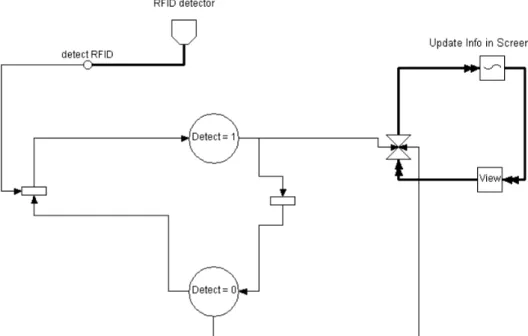
Flownets
Flownets9 are based on the Petri nets formalism and capture and combine the continuous and
discrete parts of user and interactive system interactions in virtual environments. In order to
give a general idea of the Flownets formalism, Figure 2.4 illustrates the use of this
specifica-tion to model the previous example. A clear separaspecifica-tion of continuous and discrete parts of the
interactive system interaction is made. For instance, the component RFID detector receives
data continuously (continuous flow: ). Depending on whether an RFID sensor is or is not
detected different behaviour is enabled. This separation is made in a discrete manner (states:
Detect = 1 and Detect = 0). With Flownets the states of the interaction and the events that
cause the transition states are highlighted, as can be seen in the figure. When the user is
de-tected, the sensor (detect RFID) enables the transition from state Detect = 0 to state Detect =
9
16
1. When the system is in state Detect = 1 the screen is updated (continuous flow). Next the
system comes back to state Detect = 0, ready to detect another user.
Figure 2.4: Flownets model (user arriving at an entry gate)
Willans [43] proposed an event-based notation to deal with non-WIMP interaction
tech-niques using the Marigold tool. Marigold provides toolset support for the translation from a
Flownets design of virtual environment behaviour to an implementation prototype. Using
Marigold it is possible to prototype and analyze designs of virtual environments before they
are fully implemented. In order to support these approaches, Marigold gives support to
auto-matically check properties and refine designs to a prototype. With Flownets we can define the
behaviour of systems and reason about them.
Flownets are supported by an editor that enables a hierarchical description, to animate
models and to verify properties. Flownets are appropriate for the design of virtual
environ-ment behaviour.
ICO - Interactive Cooperative Objects
This formalism is used to describe interactive systems. Its aim is to provide a precise way of
describing, analyzing and reasoning about interactive systems prior to their implementation.
17
Petri nets to describe the behaviour of the dynamic parts The state of an ICO model is defined
by the value and distribution of tokens on the places. This follows the state concept used in
Petri nets.
The ICO formalism was extended to address new challenges of different application
do-mains. For example, it was extended to support virtual reality applications and multimodal
interactive systems. Navarre et al. [32] describe its use to model virtual environment
behav-iour and multimodal systems including the fusion of several inputs, complex rendering
out-puts and 3D scenes. These systems possess several inout-puts and outout-puts leading to a wide
vari-ety of interactions.
ICO is supported by an editor that enables the animation of models and the verification of
properties. The formalism does not support the separation between continuous and discrete
parts. ICO is appropriate to model interaction techniques and adequate to reason in behaviour
and structural levels.
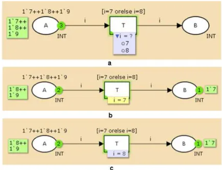
CPN - Coloured Petri nets
CPN is a language used to model concurrent systems enabling the verification of properties
on them. It is associated with a functional programming language used to define the data
types of the tokens that compose the models and to specify functions and conditions. CPN
models enable the verification of properties and simulation (similar to program execution).
State space analysis can be used to check standard properties, such as reachability,
bounded-ness, liveness and fairbounded-ness, as well as specific properties defined using the associated
lan-guage. The simulation makes it possible to see the behaviour of a model rapidly without
de-tailed human interaction. CPN modelling and analysis is supported by CPN Tools [44, 45].
These tools enable a hierarchical description of the models but without separation between
continuous and discrete parts. CPN is explained in more detail in the next section. For a brief
description of some of the main CPN qualities see the Coloured Petri net website10.
CPN is appropriate to model systems that consist of several processes that communicate
and synchronize.
10
18
CSP - Communicating Sequential Processes
Formalisms such as process algebra have been introduced for the same purpose as Petri nets.
CSP is a modelling technique, a process algebra using discrete event systems to understand
and analyse the dynamics of concurrent systems. By verifying general properties of this
for-mal model, several conceptual difficulties can be revealed at the early stages of the design
process, improving the development process. CSP is used to describe patterns of interaction
in concurrent systems [35].
Schooten [46] described a modelling technique based on CSP used to model interaction
in virtual environments and showed how a prototypes can be generated from the system
specification.
CSP is supported by an editor that enables the animation of the models and to verify
properties on them. This modelling technique enables a hierarchical description but does not
enable the separation between continuous and discrete parts.
CSP is appropriate for reasoning about systems that exhibit parallelism or distribution
and consist of multiple components that communicate to exchange information or
synchro-nize (concurrent systems).
Statecharts
Statecharts were introduced by Harel in 1987. They are used to model reactive systems and
represent a state machine using graphs: nodes denote states and connectors denote transitions.
There are currently three main variants of the formalism:
UML Statecharts;
Rhapsody Statecharts;
Classical Statecharts.
There are some differences between these formalisms. In terms of semantics Rhapsody is
closer to UML Statecharts than to the Classical Statecharts. UML and Rhapsody do not
sup-port simultaneous events or actions [47]. See the work of Crane and Dingel for a detailed
comparison [48].
Both Statecharts and Petri nets are generalisations of finite state machines and uses
tran-sitions that can enter and leave states. A transition is enabled when all sources are active
19
State is distributed since it depends on the value and state of the nodes which compose the
model.
Statecharts are supported by editors that enable the animation of the models. Models can be described hierarchically but there is no separation between the discrete and continuous parts. The automatic verification of properties is also possible.
Statecharts have been widely used to model reactive systems, even in simulation envi-ronments where a variant of Rhapsody Statecharts has been proposed [50]. The tools based on Statecharts (e.g. Statemate [51], Stateflow [52]) are more oriented to the software design
process and offer for example the capacity to generate code from models [49].
Comparison
Table 2.2 presents a comparison between the different modelling approaches. Note that the
classification presented in the table refers to extended versions of Flownets, ICO and Hynets
to deal with virtual environments.
ASUR
++
HyNets Flownets ICO CPN CSP Statecharts
Formalism - Petri Nets Petri Nets Petri Nets Petri Nets Process
Algebra
Statecharts
Editor Yes No Yes Yes Yes Yes Yes
Dynamic models No No Yes Yes Yes Yes Possible
[53]
Hierarchical
description
No Yes Yes Yes Yes Yes Yes
Automatic
verifi-cation of
proper-ties
No No Yes Yes Yes Yes Possible
[54]
Separation of
continuous and
discrete parts
No Yes Yes No No No No
20
ASUR++ does not provide a means to model the behaviour of the objects present in the
system. This is a weakness for our purpose because we need to be able to model the
behav-iour of components to drive the interaction. ASUR++ is more appropriate for reasoning at an
architectural level.
HyNets is a low level modelling approach. With low-level models we need to specify a
model with several details that are close to a low level program. We want to use models at a
reasonable level of abstraction that enables us to think about and specify virtual environments
without having to worry about specific implementation details. Additionally, HyNets has
some disadvantages compared with the other approaches. The main ones are the absence of
an editor and a tool that allows for the automatic verification of properties.
Flownets modelling has been successfully used to model the behaviour of a variety of
in-teraction techniques and world objects within virtual environments. However the tool support
that is available is less complete when compared with the other approaches (e.g. CPN).
Flownets makes a separation between continuous and discrete parts. As we are interested in
using models for ubicomp environments, and these are fundamentally hybrid systems, it is
important to consider the modelling of both parts.
The ICO modelling approach is dedicated to the specification of interactive systems and
is more appropriate to modelling the relation of physical objects present in the system. ICO
describes structural and behavioural aspects and the possible interactions that users can have
with the application. CPN is mainly appropriate for concurrent systems. This is the case of
ubiquitous environments. Both ICO and CPN models can be executed and properties can be
verified through the tool support provided.
The thesis of Basten [55] focuses on describing and comparing the Petri net and Process
Algebra formalisms. He proposed a method supporting compositional design, combining
Petri nets and process algebra. In several aspects these formalisms are complementary. Both
formalisms have a mathematical definition and are designed to reason about concurrent
sys-tems. Apart from these two common features the formalisms are totally different [55]. Petri
nets have a graphical representation in order to make them easier to use and understand for
non-experts. Process algebras are a textual formalism. This difference is quite important for
our purpose. One of the research questions of the thesis is (Section 1.3) "can a formal model
represent ubicomp environments". We want modellers to be able to model ubiquitous
envi-ronments as quickly and easily as possible. In this context the Petri net based formalism is
21
are considered to be concurrent systems and both formalisms are designed for these kinds of
systems, both formalism can be used for ubicomp environment modelling. See the work of
Basten for a detailed comparison [55].
Statecharts and Petri nets formalisms share common concepts having consequently
simi-larities but also differences. The work of Eshuis presents a detailed comparison between the
formalisms [49]. This work proposes an algorithm to translate Petri nets into equivalent
Statecharts.
In the development of APEX several possibilities were considered regarding the
model-ling of ubiquitous environments. In the end the choice was made to use CPN because of the
substantial set of tools that are available, making it easier to do our own development.
Addi-tionally, the simplicity to use and understand by a non-expert provided other benefits. While
the language lacks the features of, for example, Flownets or ASUR++ (e.g. continuous and
discrete modelling and user’s information perception modelling), we believe it provides
enough expressive power to suit our purposes and the tools available provides a rich enough
modelling, simulation and analysis environment. The continuous behaviour is dealt with via
abstractions which also makes it less expensive to analyse.
The ICO modelling approach also provides tools for the simulation and analysis of the
model. We believe that this approach can be used successfully as an alternative modelling
approach. Statecharts and standard Petri nets are less adequate for the modelling we are
aim-ing at since their scalability is less direct. Addaim-ing or removaim-ing elements of the environment
can be simply reflected in CPN by adding or removing tokens.
2.2.2 Coloured Petri nets (CPNs or CP-nets)
A more detailed description of CPNs will be provided in this section. CPNs extend standard
Petri nets by enabling tokens to have a value (in standard Petri nets all tokens are equivalent)
which can be manipulated by a programming language CPN ML based on Standard ML
(SML) [56]. CPN ML is part of the CPN notation. CPN provides a hierarchy that enables
modelling at different levels of abstraction.
CPN Tools is a computer based tool developed to support the graphical representation
and use of standard Petri nets, timed Petri nets and CP-nets. Simulation, state space analysis,
22
State space analysis is used to check standard properties and specific properties defined by
analysts.
Models developed using this tool can also use time to evaluate the performance of the
systems. CPNs were developed for systems where synchronisation, communication and
re-source sharing are important features of the modelled system.
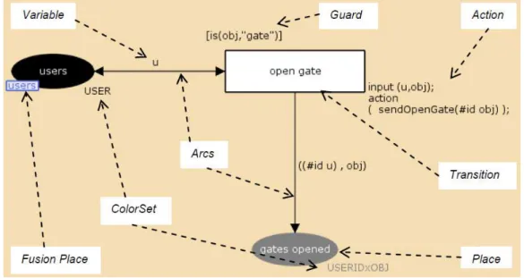
“A CPN model consists of a set of modules which each contains a network of places,
arcs and transitions. The modules interact with each other through a set of well-defined
inter-faces, in a similar way as known from many modern programming languages” [57]. Each
place can contain tokens that carry data values, called token colours. The type of these values
can vary in complexity (e.g. a String, a product, a record, etc.) and are specified in the same
way as types are specified in programming languages. Each place can only carry tokens of a
specified type. This is called the colour set of the place. The CPN components (places, arcs
and transitions) can have inscriptions associated with them (CPN ML constructs that affect
the behaviour of a net). See CPN Tools website11 for more information. Figure 2.5 represents
the graphical representation of the CPN components and elements. See, for example, the
Ac-tion element. The sendOpenGate function in it is described in CPN ML within the CPN
Tools.
Figure 2.5: CPN graphical syntax
11