Applied Sonochemistry Applied Sonochemistry: Uses of Power Ultrasound in Chemistry and Processing.
Applied Sonochemistry
Professor Timothy J. Mason Professor John P. Lorimer Coventry University Priory Street Coventry CV1 5FB U.K.
This book was carefully produced. Nevertheless, authors and publisher do not warrant the information contained therein to be free of errors. Readers are advised to keep in mind that statements, data, illustrations, procedural details or other items may inadvertently be inaccurate.
Library of Congress Card No.:Applied for. British Library Cataloguing-in-Publication Data: A catalogue record for this book is available from the British Library.
Die Deutsche Bibliothek ± CIP Cataloguing-in-Pub-lication Data:
A catalogue record for this publication is available from Die Deutsche Bibliothek.
ãWiley-VCH Verlag GmbH, Weinheim 2002 All rights reserved (including those of translation in other languages). No part of this book may be reproduced in any form ± by photoprinting, mi-crofilm, or any other means ± nor transmitted or translated into machine language without written permission from the publishers.
In this publication, even without specific indi-cation, use of registered names, trademarks, etc., and reference to patents or utility models does not imply that such names or any such information are exempt from the relevant protective laws and regulations and, therefore, free for general use, nor does mention of suppliers or of particular commercial products constitute endorsement or recommendation for use.
Printed on acid-free paper.
Printed in the Federal Republic of Germany.
Composition Mitterweger & Partner Kommunikationsgesellschaft mbH, Plankstadt Printing betz-druck GmbH, Darmstadt Bookbinding Groûbuchbinderei J. SchaÈffer GmbH & Co. KG, GruÈnstadt
Contents
1 Introduction to Applied Ultrasonics 1
1.1 Background 1
1.2 Sound Frequency Ranges 3
1.3 Some Current Industrial Uses of Ultrasound 4 1.3.1 Ultrasonic Welding 5
1.3.2 Ultrasonic Cleaning and the Decontamination of Surfaces 7 1.3.3 Ultrasound in Biology and Medicine 9
1.3.4 Engineering Applications 12 1.3.5 Processing Applications 17 1.4 Ultrasound in Chemistry 20
1.4.1 Reactions Involving Metal or Solid Surfaces 21
1.4.2 Reactions Involving Powders or Other Particulate Matter 21 1.4.3 Emulsion Reactions 22
1.4.4 Homogeneous Reactions 22
2 General Principles 25 2.1 Introduction 25
2.2 Intensity and Pressure Amplitude 31 2.3 Sound Absorption 33
2.4 Bubble Formation and the Factors Affecting Cavitation Threshold 36 2.4.1 Effect of Gas and Particulate Matter 36
2.4.2 Effect of Viscosity 39
2.4.3 Effect of Applied Frequency 39 2.4.4 Effect of Temperature 42
2.5 Motion of the Bubble in the Applied Acoustic Field 45 2.5.1 Transient Cavitation 53
2.5.2 Stable Cavitation 55
2.6 Summary 56
2.6.1 Frequency 56 2.6.2 Solvent 57 2.6.3 Temperature 57
2.6.4 Gas Type and Content 58 2.6.5 External Applied Pressure 59
2.6.6 Intensity 59
Appendix 1: Relationship Between Particle Velocity (m) and Acoustic Pressure (P a) 61 Appendix 2: Critical Pressure (PK) and Bubble Radius Relationship 62
Appendix 3: Time of Bubble Collapse 65 Appendix 4: Motion of Cavity Wall 68
Appendix 5: Maximum Bubble Temperature (Tmax) and Pressure (Pmax) 69 Appendix 6 Bubble Dynamics 72
Operation of the Programme 72
3 Synthesis 75
3.1 Introduction 75
3.2 The Various Sites for Sonochemical Reactions 78 3.3 An Attempt to Define the Laws of Sonochemistry 81 3.4 Homogeneous Reactions 83
3.5 Heterogeneous Sonochemistry 93
3.5.1 Heterogeneous Reactions Involving a Metal as a Reagent 93
3.5.1.1 Preparation of Active Metals from Metals their Salts and Complexes 93 3.5.1.2 In situSonochemical Activation of Metals 97
3.5.2 Heterogeneous Reactions Involving Non-Metallic Reagents 110 3.5.2.1 Addition Reactions 110
3.5.2.2 C Alkylation Reactions 113 3.5.2.3 OandNAlkylation Reactions 115 3.5.2.4 Reduction and oxidation Reactions 117
3.6 Sonochemical Preparation of Ultrafine Powders and Nanostructured Materials 120
3.6.1 Metal Powders 121
3.6.2 Metal Oxide and Other Powders 123 3.6.3 Supported Nanopowders 124
4 Sonochemistry in Environmental Protection and Remediation 131 4.1 Introduction 131
4.2 Water Purification 132
4.2.1 Biological Decontamination 132
4.2.1.1 The Mechanisms of Ultrasonic Action on Cellular Material 132 4.2.1.2 Ultrasonic Destruction of Biological Contaminants in Water 134 4.2.2 Chemical Decontamination 137
4.2.2.1 The Sonication of Water 137 4.2.2.2 The Effect of Ultrasound Alone 138
4.2.2.3 Combined Application of Ultrasound with Ozone 141
4.2.2.4 Combined Application of Ultrasound with Ultraviolet Light 142 4.2.2.5 Combined Application of Ultrasound with Electrochemistry 142 4.3 Surface Decontamination 144
4.4 Decontamination of Soil 145 4.4.1 Surface Cleaning of Particles 146
4.4.2 Leaching of Pollutants from within Particles 147
4.5 The Control of Air-Borne Contamination 149 4.6 Treatment of Sewage Sludge 152
4.6.1 Ultrasonically Assisted Digestion 152 4.6.2 Ultrasonically Assisted Dewatering 153
5 Polymers 157
5.1 Introduction 157
5.2 Degradation of Polymers 161
5.3 Factors Affecting Polymer Degradation 170 5.3.1 Frequency 170
5.3.2 Solvent 172 5.3.3 Temperature 174 5.3.4 Nature of the Gas 175 5.3.5 Intensity 179
5.3.6 External Pressure 185
5.3.7 R.M.M. and Concentration 188 5.3.8 Nature of the Polymer 190 5.4 Degradation Mechanisms 191 5.5 Polymer Synthesis 196
5.6 Ultrasonic Processing of Polymers 214 5.6.1 Treatment of Plastics 214
6 Sonoelectrochemistry 225 6.1 Introduction 225
6.2 Electrolytic Discharge 231
6.3 Electroplating in the Presence of Ultrasound 234 6.3.1 Chromium Plating 235
6.3.2 Zinc Electroplating 243 6.3.3 Iron Electroplating 244 6.3.4 Copper Electroplating 245 6.3.5 Electrolytic Removal of Silver 246 6.3.6 Nickel Electroplating 247 6.4 Sonoelectroorganic Synthesis 249 6.4.1 Electrooxidative Syntheses 250 6.4.2 Electroreductive Syntheses 255 6.4.3 Organometallic Systems 257 6.4.4 Electroinitiated Polymerisations 258
6.5 Summary 263
7 Ultrasonic Equipment and Chemical Reactor Design 267 7.1 Methods for the Generation of Power Ultrasound 267 7.1.1 Gas-Driven Transducers 268
7.2.1 Whistle Reactor 276
7.2.2 Ultrasonic Cleaning Bath 276
7.2.3 Laboratory Equipment Based on the Ultrasonic Cleaning Bath 278 7.2.4 Direct Immersion Sonic Horn 279
7.2.4.1 Horn Design 280
7.2.5 Laboratory Scale Reactors Involving Probe Systems 283 7.3 Large Scale Applications 286
7.3.1 Whistle Systems 286 7.3.2 Low Intensity Systems 287 7.3.3 High Intensity Systems 288
Subject Index 295
Preface
When Phil Lorimer and I had completed the book for Ellis Horwood over ten years ago we really did feel as though we were contributing to a solid foundation for our chosen field of research in sonochemistry, and so it has proven to be.
Sonochemistry has moved on substantially since those days. Most of the major in-ternational acoustics meetings now include a component of relating to the applications of power ultrasound in chemistry and processing. Indeed a biennial conference with this title was first launched in Toulouse in 1997 and the European Society of Sono-chemistry has had seven major meetings to date. On the one hand research into so-nochemistry has expanded in terms of groups involved but on the other there is a tendency to concentrate on areas of particular interest such as sonoluminescence, food technology, nanoparticle synthesis, electrochemistry, environmental protection and, of course, chemistry and chemical processing. The first two of these have seen the publication of edited texts [1, 2] which have concentrated these specialist topics. In our book we have revised and expanded a number of chapters from the original text and added two others: environmental protection and electrochemistry.
It is our hope that this book will present the reader with an appreciation of current trends in the applications of sonochemistry. The theoretical aspects of the subject are, once again, included but not emphasised. It is our intention to concentrate on the uses of sonochemistry and to leave the interested reader to find the more complex math-ematical aspects from other sources.
± Ultrasound in Food Processing,M. Povey and T. J. Mason (eds.), Blackie Academic and Professional, pp 282, 1998, ISBN 0-7514-0429-2.
± Sonochemistry and Sonoluminescence,NATO ASI Series, L. A. Crum, T. J. Mason, J. L. Reisse and K. S. Suslick (eds.), Kluwer Academic Publishers, pp 404, 1999, ISBN 0-7923-5549-0.
Coventry, 2001 Tim Mason
Speakers at the first international symposium on Sonochemistry organised by T. J. Mason. Held as part of the Royal Society of Chemistry Annual Congress, Warwick University, April 1986. The affiliations of the speakers are those which were current at the time of the conference.
Front Row (left to right) R. Verrall
Department of Chemistry University of Saskatchewan Saskatoon Canada A. Henglein Bereich Strahlenchemie Hahn-Meitner-Institut Berlin Germany
T. J. Mason School of Chemistry Coventry Polytechnic Coventry
United Kingdom
P. Boudjouk
Department of Chemistry North Dakota State University North Dakota
USA
K. S. Suslick
School of Chemical Sciences University of Illinois at Urbana Champaign
Ilinois USA
C. Dupuy Chimie Recherche
Universite Scientifique et Medical de Grenoble
Grenoble France
Second Row (left to right) J. Lindley
School of Chemistry Coventry Polytechnic Coventry
United Kingdom
P. Riesz
National Institutes of Health Bethesda
Maryland USA
T. J. Lewis
Department of Electronic Engineering
University College of North Wales Bangor United Kingdom J. Perkins Sonic Systems Marlborough Wiltshire United Kingdom
E. J. Einhorn Chimie Recherche
Universite Scientifique et Medical de Grenoble
Grenoble France
P. Kruus
Department of Chemistry Carleton University Ottawa
Canada
Back Row (left to right) R. S. Davidson Dept of Chemistry City University London United Kingdom
J.-L. Luche Chimie Recherche
Universite Scientifique et Medical de Grenoble Grenoble France B. Pugin Ciba-Geigy Basle Switzerland
J. P. Lorimer School of Chemistry Coventry Polytechnic Coventry
acoustic
± motion of the bubble in the applied acoustic field (see there) 45 ± 56 ± pressure 37, 61
± wave theory 25
air-borne contamination control, water purification 149 ± 152 ± acoustic standing waves 149 ± defoaming liquids 151 ± dust suppression 149
± emission in coal combustion 150 ± mist suppression 151
alcohols, oxidation 119 alkali metals 98 ± Barbierreaction 99 ± Bouveaultreaction 100 ± lithium diisopropylamide 100 ± magnesium 98
± Wurtzcoupling 99 alkylation
± C alkylation reactions (see there) 113 ± 114 ± Nalkylation reactions (see there) 115 ± 117 ± Oalkylation reactions (see there) 115 ± 117 amino acids 112
amorphous ± catalysis 123 ± iron 121
± magnetic metals 122 ± MoS2 124
± nickel 121 anti-algae 135 apparatus
± labaratory 275 ± 285 ± ± cleaning bath 275 ± 279 ± ± cup-horn 275, 286 ± ± dimple cell 284 ± ± flow cell 285
± ± probe (or horn) system (see there) 275, 279 ± 282
± ± simple pressure cell 284 ± ± whistle reactor 276
± large scale applications 286 ± 290 ± ± cross-section shapes for flow
processors 290
± ± high intensity system 288 ± ± low intensity system 287 ± 288 ± ± Nearfieldacoustic processor (NAP) 291 ± ± radial ultrasonic emitters 292 ± ± reaction tube with externally bonded
transducers 292
± ± reaction tube with probe inserts 289 ± ± reaction tube with transduce inserts
289
± ± submersible transucer assembly 288 ± ± whistle systems 286 ± 287
± for organo-zinc reagents 106 aqueous polyethylene oxide,
intensity effect of 184 aromatic
± carbon-halogen bond, cleavage of 117 ± nitro group, reduction of 117 ASDIC echo-sounder 2 atomisation 15 ± 16 aziridine 111
bacterial ± biofilms 145 ± removal 144 Barbierreaction 99
benzaldehyde, electroreduction of 255 benzoic acid, electroreduction 256 benzyl / benzylic
± bromide, electroreduction 256 ± position, oxidation at 118 biological cell disruption 9 block, polymer synthesis 196 ± 197 ± cellulose 196
± graft polymers 196
± polymethyl methacrylate 196 ± poly(methyl phenyl silane) 197 ± polystyrene 196
Bouveaultreaction 100 bubble
± collapse time 46, 65 ± dynamics 73
± formation (see alsocavitation threshold) 36 ± 45
± motion of the bubble in the applied acoustic field (see there) 45 ± 56, 65 ± radius 62
± temperature (2 % $
! ( & ! ' '' # ! $ "
" ' ! ! % ! $ ! " ! ! ' ! ! !
a ! ! ! " $ " " $
. )(-3,
! " ! $ (000 ' (450
! "
6 ' ' " ' " '' '! # % '! # % '' '! " " ! a !
$' $! " " $' "
(7
! $ "
%% " . $
$
'
" $
" % "
" ! $ $ ,*/0( *7+,4 " . ' $ $ ! " ! $
!
" '
' !
!
"
& " '
%% ! " % $ %% # . "
" ! " ' "
& '
. " . . . # ' $$ $$ %
" % '
'! ! ! # %
" $ $ ! ! ' " ! "
" ' !
" " '
$ " ' ! " !
! " " !'
" 1 ! ! $
& !'
$' $!
" ! !'
" !
" $ $
" ! ! !
. ! ! $ $
6)*
" ' !
' '' '' '! ! ! ' # ' " ! '' ' ' ' " !$ ' ' ! ! 6)* 8" ' % ' % '
" ' !
$
" ! "
' "
" "
" $ ! $ % ' ! " ' !
%" ' " '
!
" ! $ $
" "
!
" ! ' # % ' % '
% ' " ' -)), ' ' $ $ $! $ , $ $ '' " " ' !
a # ! $
b ! c
' " ' #
" ! " # ' # # ! " $ # ! !'
& !' !'
$$ " ! ' ! # $ ' 8" " " ! !'
! " !'
% ))-- " % "
)(-3, .
" ! !
!
!! !
" ! $ $ !
! " ! !' ! & ! ! ! ! ! !
" $ !
! !
. ! ! $ $
& !' !!
$$
$$ " !'
" !! " % )* (7 . % "
)7
+97
" & " ! " )), $ $ $ %" '
))-- " % )7 " ' ' # ! # ' $ % " $ & ::: $ +,- ! +,- ! & ! " ' ' ' '
+97
# '
" $ $ $ . $ % c
. )(-3,
" % ))--
%&$
& & $ % % $ $ &
" " '
" ' '
" ! " !
" . " $ % $
% !
. % '
!
" "
" % '
" *;2 $
. 76 ! . %
& . $ % $ $ " . $ ' #. $ ! -)), ' -+5< " ! "
.
"
" $ $
'' '!
" ! % % ' ' !$ # $ !
" ' !
! '
' ! " 4:):):
! !
! -+5< " ! !$ '! " !
& ! !
" " $$ # $ 6 " $ " $ " !
$ $' $!
$ $
$!
a
!'
" ) $
!!
" ) $ ! $ " $ !' " " $$ $ $ $ ' !
" ' ' ' % ' ' ' ! !' & ! !' . ! - % $
% " ' '
" 4:):): ' '
! ' " '$ '
" $ ! $ % ' ! " ' ! = " %" ' " " 1 ! " &" " ' " '' '
" $
% ! '! '! " % % $
"$ . $
!
" $ !
" "
% 4:):): " "
' ''
*;2 $
" " " " % % . $ ' " " ' " ' *7+,4 ' ' ' " ' !$
' ' !
" ' $ " " !
' % $ # ! $ " ' # %&$ " ! '' # ! ' ' ' " !
" # ' # # ! ' " . $ $ $ , $ $ $ ! > ' " ' ! # ! " . $ " " $ $' . $ $ " & % )*
(7
. % "
)7
+97
" ' !
" ! " # ! $ " " $ ! . % $ $ ' ' " ' " " " " " "
" !
" " ' ' ( & " !! % . $ # . . ! ! $ $
" . " $ $
"
" $ $
& $
"$ $
% % $
" $
1
Introduction to Applied Ultrasonics
1.1 Background
If you were asked what you knew about ultrasound you would almost certainly start with the fact that it is used in animal communications (e. g. bat navigation and dog whistles). You might then recall that ultrasound is used in medicine for foetal imaging, in underwater range finding (SONAR) or in the non-destructive testing of metals for flaws. For a chemist however sound would probably not be the first form of energy that would be considered for the excitation of a chemical reaction. Indeed up to a few years ago the use of ultrasound in chemistry was something of a curiosity and the practising chemist could have been forgiven for not having met the concept. To increase chemical reactivity one would probably turn towards heat, pressure, light or the use of a catalyst. And yet, if one stops for a second to consider what is involved in the transmission of a sound wave through a medium it is perhaps surprising that for so many years sound was not considered as a potential source of enhancement of chemical reactivity. The only exception to this being the green fingered chemist who, in the privacy of his own laboratory, talks, sings or even shouts at his reaction. After all, sound is transmitted through a medium as a pressure wave and the mere act of transmission must cause some excitation in the medium in the form of enhanced molecular motion. However, as we will see later, in order to produce real effects the sound energy must be generated within the liquid itself. This is because the transfer of sound energy from the air into a liquid is not an efficient process.
vibration (sound) energy ± rather like a loudspeaker. At sufficiently high alternating potential high frequency sound (ultrasound) will be generated.
The earliest form of an ultrasonic transducer was a whistle developed by Francis Galton (1822 ± 1911) in 1883 to investigate the threshold frequency of human hearing (see Chapter 7) [4]. Galton himself was a remarkable man. As well as inventing the whistle that carries his name he explored and helped map a portion of the African interior, invented the weather map and developed the first workable system for clas-sifying and identifying fingerprints. His whistle was part of his study of sensory per-ception, in this case to determine the limits of hearing in terms of sound frequencies in both humans and animals.
The first commercial application of ultrasonics appeared around 1917 and was the first ªecho-sounderº invented and developed by Paul LangeÂvin (1872 ± 1946). He was born in Paris and was a contemporary to Marie Curie, Albert Einstein and Hendrik Lorentz. He was noted for his work on the molecular structure of gases, analysis of secondary emission of X-rays from metals exposed to radiation and for his theory of magnetism. However LangeÂvin is more generally remembered for important work on piezoelectricity and on piezoceramics. The original ªecho-sounderº eventually became underwater SONARfor submarine detection during World War 2. The transducer was a mosaic of thin quartz crystals glued between two steel plates (the composite having a resonant frequency of about 50 kHz), mounted in a housing suitable for submersion. The early ªecho sounderº simply sent a pulse of ultrasound from the keel of a boat to the bottom of the sea from which it was reflected back to a detector also on the keel. For sound waves, since the distance traveled through a medium1/2timevelocity (and the velocity of sound in seawater is accurately known) the distance to the bottom could be gauged from the time taken for the signal to return to the boat. If some foreign object (e. g. a submarine) were to come between the boat and the bottom of the seabed an echo would be produced from this in advance of the bottom echo. In the UK this system was very important to theAlliedSubmarineDetection InvestigationCommittee during the war and became popularly known by the acro-nym ASDIC. Later developments resulted in a change in the name of the system to SONAR(SOund Navigation And Ranging) which allowed the surrounding sea to be scanned. The original ASDIC system predated the correspondingRAdioD etec-tionAndRanging system (RADAR) by 30 years.
much shorter wavelengths it is possible to detect much smaller areas of phase change i. e. give better `definition'. The chemical applications of high frequency ultrasound are concerned essentially with measurements of either the velocity of sound through a medium or the degree to which the sound is absorbed as it passes through it. These applications are diagnostic in nature and do not effect the chemistry of the system under study.
When more powerful ultrasound at a lower frequency is applied to a system it is possible to produce chemical changes as a result of acoustically generated cavitation (see below). Cavitation as a phenomenon was first identified and reported in 1895 by Sir John Thornycroft and Sidney Barnaby [5]. This discovery was the result of inves-tigations into the inexplicably poor performance of a newly built destroyer HMS Dar-ing. Her top speed was well below specifications and the problem was traced to the propeller blades that were incorrectly set and therefore not generating sufficient thrust. The rapid motion of the blades through water was found to tear the water structure apart by virtue of simple mechanical action. The result of this was the pro-duction of what are now called cavitation bubbles. The solution to this problem lies in using very wide blades covering about two-thirds of the disc area of the propeller, so as to present a very large surface contact with the water. This helps to prevent disruption under the force necessary to propel the vessel. As ship speeds increased, however, this became a serious concern and the Royal Navy commissioned Lord Rayleigh to inves-tigate. He produced a seminal work in the field of cavitation which confirmed that the effects were due to the enormous turbulence, heat, and pressure produced when cav-itation bubbles imploded on or near to the propeller surface [6]. In the same work, he also observed that cavitation and bubble collapse was also the origin of the noise made when water is heated towards boiling point.
Since l945 an increasing understanding of the phenomenon of cavitation has devel-oped coupled with significant developments in electronic circuitry and transducer design (i. e. devices which convert electrical to mechanical signals and vice versa). As a result of this there has been a rapid expansion in the application of power ultra-sound to chemical processes, a subject which has become known as ªSonochemistryº.
1.2
Sound Frequency Ranges
Sound frequencies are recorded in units of Hertz (1 Hertz1 cycle per second). The range of human hearing for a young person is from about 20 Hz to 20 kHz (the upper limit reduces with age). Within this range lies middle C at 256 Hz. Other species have a wider hearing range e. g. dogs 40 Hz to around 45 kHz and bats 1 kHz to 150 kHz. Bats use high frequency sound (20 ± 100 kHz in air) for echo location as do whales
(50 ± 200 kHz in water). Ultrasound itself is defined in terms of human hearing and is sound having a frequency higher than that to which the human ear can respond (i. e. >20 kHz). The upper limit of ultrasonic frequency is one that is not sharply defined but is usually taken to be 5 MHz for gases and 500 MHz for liquids and solids. The uses of ultrasound within this large frequency range may be divided broadly into two areas.
The first area involves low amplitude (higher frequency) sound and is concerned with the physical effect of the medium on the wave and is commonly referred to as ªlow powerº or ªhigh frequency ultrasoundº. Typically, low amplitude waves are used for analytical purposes to measure the velocity and absorption coefficient of the wave in a medium in the 2 to 10 MHz range. Information from such measure-ments can used in medical imaging, chemical analysis and the study of relaxation phenomena and this will be dealt with later.
The second area involving high energy (low frequency) waves, known as ªpower ultra-soundº, and lies between 20 and 100 kHz. It is used for cleaning, plastic welding and, more recently, for sonochemistry (see Fig. 1.1). In fact the range available for sonochem-istry has been extended to 2 MHz with the development of high power equipment cap-able of generating cavitation within liquid systems at these higher frequencies.
Before we discuss how sound energy can affect chemistry and chemical processing it would be instructive to explore some of the broader applications of the uses of ultra-sound in industry [7 ± 9]. Some of these have been in existence for many years and a range of such are shown in Tab. 1.1. A few of these are explored in more detail in later chapters.
Two of these applications have provided the direct antecedents of the types of equip-ment now commonly used for sonochemistry namely ultrasonic welders and cleaning baths.
Ultrasonic Welding
A large proportion of ultrasonic equipment currently in industry is used for welding together thermoplastic components for the consumer market [10]. A simple form of ultrasonic welding equipment is shown in Fig. 1.2. It consists of a generator producing an alternating frequency of around 20 kHz which drives a transducer assembly in a housing that contains controls for both the amplitude and duration of ultrasonic pulse required. This assembly also provides the pneumatic pressure required during the welding process. A shaped tool is attached to the horn and together these comprise a resonating unit that is the basic instrument to provide ultrasonic vibrations. With this tool two thermoplastic parts of compatible material may be joined together quickly and efficiently. The mechanical vibration of the horn contact face (the vibrational am-plitude employed is typically 50 ± 100lm) is passed to the upper component which is correspondingly vibrated against the lower part at 20 000 times per second. The small initial contact area is where energy is most readily dissipated in the form of frictional
Tab. 1.1.
Field Application
Biology, Biochemistry Homogenisation and cell disruption: Power ultrasound is used to rupture cell walls in order to release contents for further studies.
Engineering Ultrasound has been used to assist drilling, grinding and cutting. It is parti-cularly useful for processing hard brittle materials e. g. glass, ceramics. Other uses of power ultrasound are welding (both plastics and metals) and metal tube drawing.
Dentistry Cleaning and drilling of teeth, also for curing glass ionomer fillings.
Geography, Geology Pulse/echo techniques are used in the location of mineral and oil deposits and in depth gauges for seas and oceans. Echo ranging at sea has been used for many years (SONAR).
Industrial Pigments and solids can be easily dispersed in paint, inks and resins. Engi-neering articles are often cleaned and degreased by immersion in ultrasonic baths. Two less widely used applications are in acoustic filtration and metal casting.
Medicine Ultrasonic imaging (2 ± 10 MHz) is used, particularly in obstetrics, for observing the foetus and for guiding subcutaneous surgical implements. In physiotherapy lower frequencies (20 ± 50 kHz) are used in the treatment of muscle strains, dissolution of blood clots and cancer treatment.
heat. The rise in temperature causes localised melting of the material. The parts are continuously held together under pneumatic pressure thus maintaining the melting process until the vibrations are stopped. Pressure is further maintained for a fraction of a second until the liquid material has set. The strength of the finished weld is pri-marily dependent upon correct choice of materials and component design.
Ultrasonic welding is generally used for the more rigid amorphous types of thermo-plastic. These are most suitable for welding because the ultrasonic vibration can travel through the bulk plastic of the component to the joint. The more flexible and crystal-line the plastic material, the more readily it will absorb the vibration energy as it travels through the material i. e. the ªsoundº is attenuated (or deadened) rapidly as it passes through. This type of plastic is generally only welded in the form of thin sections of sheet or film. For plastic welding it is particularly important that the vibrational energy is transmitted only to the joint and not the body of the material, since any warming of the bulk material may lead to a release of internal molding stresses and produce dis-tortion.
Thermoplastics have two properties which make them particularly suited to ultra-sonic welding (a) low thermal conductivity and (b) melting or softening temperatures of between 100 and 2008C. As soon as the ultrasonic power is switched off the sub-strate or bulk material becomes a heat sink, giving rapid cooling of the welded joint. When more traditional conductive heating is used for welding however the thermal
Fig. 1.2.
gradient developed must be reversed before cooling occurs, leading to long heating/ cooling process cycles. Another major advantage of the use of ultrasound is the high joint strength of the weld, reaching 90 ± 98 % of the material strength. Indeed test samples usually break in the body of the material and not at the weld itself.
To emphasise the advantages of ultrasonic welding compared with the more tradi-tional approach several examples can be quoted. For aesthetic reasons it is important to avoid distortions in spectacle frames and this has been achieved by ultrasonically weld-ing the metal hweld-inge joint into the plastic frame. Other examples are to be found in the automotive industry where, for example, the car rear reflector cluster will normally have its plastic lens welded into place and the threaded brass insert may well have been inserted by ultrasound. In the UK the 13A mains plug often has the brass threaded nut ultrasonically inserted into the lid; the outer knurling is trapped in place by the plastic melted by the vibrational energy. Emulsion paint cans rust and discolour the paint, consequently several firms now use plastic cans to avoid this problem. The rim, which takes the snap-on lid, is welded ultrasonically to the body in an automated high-speed canning line.
Ultrasonic welding is not only restricted to plastics but can also be used for metals. In this case the ultrasonic motion must be lateral rather than vertical so that frictional heating is induced between the surfaces. One typical application is in the welding of aluminium which is difficult by normal methods because of its tenacious surface oxide. With ultrasonic metal welding ± a form of low temperature diffusion welding ± the oxide layer is easily broken up and adsorbed within the metal surrounding the weld. Welding by lateral vibrational movement is readily achieved using this technique without the formation of brittle intermetallic compounds. Ultrasonic metal welding, like plastic welding, permits the very delicate joining of components. In flute manu-facture it is clearly important to avoid distortion when attaching pillars to the flute body. The well known musical instrument makers Boosey and Hawkes largely elimi-nated the problem by using an ultrasonic stud-welder for the process thus avoiding the heat normally associated with hard soldering.
Ultrasonic Cleaning and the Decontamination of Surfaces
Ultrasonic cleaning is another major application for power ultrasound. It is now such a well-established technique that laboratories without access to an ultrasonic cleaning bath are in a minority. It is important to recognise the historical significance of the development of ultrasonic cleaning technology on the growth of sonochemistry be-cause, in the early years, the humble laboratory cleaner was almost certainly the first ultrasonic apparatus used by chemists.
Ultrasound is particularly useful in surface decontamination since cavitation bubble collapse near a solid is non-symmetric (see Fig. 3.4) and produces a powerful jet which will dislodge dirt and bacteria. The particular advantage of ultrasonic cleaning in this context is that it can reach crevices that are not easily accessible using conventional cleaning methods. Objects that can be cleaned range from large crates used for food packaging and transportation to delicate surgical implements such as endoscopes. This breadth of application was recognised some years ago in a general patent that relates to the use of ultrasound as a method of pasteurisation, sterilisation and decon-tamination of instruments and surfaces used within the medical, surgical, dental and food processing industries [11]. The use of ultrasound allows the destruction of a variety of fungi, bacteria and viruses in a much reduced processing time when com-pared to thermal treatment at similar temperatures. The removal of bacteria from various surfaces is of great importance to the food industry and can be efficiently accomplished with the combined use of sonicated hot water containing biocidal detergent [12].
A good example of the use of ultrasonic technology was the raising of the Tudor warship the ªMary Roseº from the sea-bed of the Solent in England in 1982. The ship had lain buried by preserving silt, for 437 years and ultrasound was used in two ways to assist in this historic ªrescueº [13]. The initial location of the wreck was greatly assisted by SONAR. Subsequently, following her recovery, strenuous ef-forts were made by the `Mary Rose' Trust to preserve the 17 000 or so artifacts recov-ered from the wreck. These included hundreds of bows, arrows, musical instruments and personal objects such as clothes, footwear, coins and so forth. The prospect of cleaning and preserving this vast amount of material by laborious soaking and rinsing had proved daunting even before the `Mary Rose' itself broke the surface of the waves. A large ultrasonic cleaning bath (donated by the UK company Kerry Ultrasonics) was used to clean items as bulky as wooden gun carriages but could as easily be used for smaller items. One of the major problems in preserving artifacts constructed of or-ganic materials ± wood and leather ± is that they often have become impregnated with iron deposits. These deposits have to be removed to prevent further deteriora-tion, since iron staining and rust block the pores of the organic materials, preventing effective penetration of the chemical preservatives. Ultrasonic cleaning is very effective in removing such deposits and can, at a later stage, be used to improve the penetration of preservatives into the material.
Ultrasound in Biology and Medicine
Biological cell disruption
One of the first uses of power ultrasound in biology was the disruption of cell walls to release the contents for in vitro studies. The type of apparatus used for this purpose is a direct descendent of the welding equipment described above. A horn resonating at 20 kHz is dipped into a suspension of biological cellular material. The vibrating tip generates cavitation within the liquid immediately below the tip and the resulting forces and turbulence can cause cell disruption. The process depends upon the effi-ciency with which the cell wall can be broken to release the cellular contents without at the same time destroying them. This is much more difficult than it would appear. The problem is that most simple one-cell organisms have an exceedingly tough cell wall which is only a few microns in diameter, and similar in density to the medium that surrounds it. On the other hand the protein and nucleic acid components contained within the cell are large macromolecules, easily denatured by extreme conditions of temperature or oxidation.
Maximum disruption is obtained in a zone close to the probe tip and the biological cells must be kept here for sufficient time to allow disruption to take place. A delicate balance must therefore be struck between the power of the probe and the disruption rate since power ultrasound, with its associated cavitational collapse energy and bulk heating effect, can denature the contents of the cell once released. Indeed for this type of usage it is important to keep the cell sample cool during sonication. The method is very effective and continues to be an important tool in microbiology and biochemistry research.
Ultrasound in diagnostic medicine
Unlike the echo-sounding applications referred to above diagnostic medical scanners (and NDT equipment) work at very low power levels (milliwatts) on a pulsed echo system. As its name suggests diagnostic (or high frequency) ultrasound provides a non-invasive technique for scanning the human body and can be considered to be complementary to X-ray and magnetic resonance methods. One of the most publi-cised uses of diagnostic ultrasound has been in foetal imaging [14]. Another major usage is as a continuous and non-hazardous method of visualising the position of needles and other surgical implements as they are used within the body.
The origins of acoustic sensing in medical diagnosis go back a long way. Physicians have always used the direct approach of listening for the sounds generated from the heart and lungs but in the 18th century a new technique was introduced known as ªpercussionº. This involved the physician tapping on the surface of the skin of a pa-tient and listening for the resonant note emitted by the air-filled or liquid filled spaces
within the body. Practice in the method allows diagnosis of a range of medical con-ditions.
In the medical use of diagnostic ultrasound, high-frequency acoustic pulses of short duration are propagated from a source placed on the outer skin of the patient. The source is both a sender of pulses and a receiver of echoes and a gel is used to ensure good acoustic contact with the skin. The pulses proceed in more or less straight lines and are scattered as they encounter various physical gradients or boundaries within tissues. ªBack-scatterº, in which the pulses are reflected 1808, results in a series of echoes which can be detected at the skin surface. The lapse of time between launching and receiving a pulse is proportional to the depth of the reflecting tissue (the average sound velocity in body tissues is about 1.54 km s1
) Likewise, the time lapse between echoes corresponds to the space between structures which are reflecting the pulses. Signals can also vary in strength, or amplitude, depending on the specific features of the reflecting structures, such as their composition, compressibility, and density.
An ultrasound image is synthesised line by line, each line of the image representing the echo pattern of an individual acoustic pulse. The result is a spatial map of phase boundaries within the tissues. Signal amplitude is portrayed in a gray scale of tonal gradations, with the strongest reflected signals shown as intense white and the ab-sence of a signal as black. Today's devices use acoustic pulses with an average fre-quency in the range of 3 ± 10 MHz; pulse wavelengths and the corresponding resolu-tion features of the image are equal to or less than 1 mm.
Medical scanners have an array of transducers in each probe and are capable of providing thousands of measurements of the small changes in the velocity of sound as it passes through various phase changes within the body. This information is fed to computers that create a television picture of the internal tissues of the human body.
Ultrasound in therapeutic medicine
One of the first applications of ultrasound in medicine was the so-called ultrasonic massage introduced in Germany before the Second World War. This was introduced as a substitute for the hands of the masseur in patients who had suffered from frac-tures and similar injuries. Rubbing movements are capable of improving the circula-tion very considerably and help also to break down adhesions between muscles and their sheaths that limit the range of movement. The use of ultrasound for the treat-ment of sporting injuries, particularly strains and ªtennis elbowº is now commonplace as equipment for this purpose is readily commercially available to the physiotherapist. This is one of the first uses of ultrasound in the treatment of medical problems and is part of a new field of medicine called therapeutic ultrasound [15].
inserted into the blood vessel. The device is brought close to the clot at which point a fibrolytic enzyme is released (Fig. 1.3a). When the transducer is activated the acoustic energy accelerates the enzymatic dissolution of the clot.
Another use involves a technique known as High Intensity Focused Ultrasound (HIFU) is used in the treatment of cancer (Fig. 1.3b). In this methodology an array of transducers is constructed to produce a focus in the shape of a rugby football only a millimeter or so in cross section and a few millimeters long. When applied to the skin of a patient the focus can be targeted accurately on cancerous tissue within the body and thermally destroy it. In a sequence of exposures the focus can be moved to cover the whole of the infected region. At lower powers the focused ultrasound can also be used to enhance the action of a chemotherapy agent such as a porphyrin which is known to become localised in a region of cancerous cells. The ultrasound is again targeted in the affected region and is thought to promote the types of radical reaction which are generally considered to be involved in chemotherapy.
Ultrasound in dentistry
The connection between the use of ultrasound for the machining and drilling of hard materials (see below) and dentistry is clear since tooth enamel is a very hard material. In the dentist's surgery a new instrument has been introduced which is essentially a small ultrasonic probe operating at 25 kHz with a variety of attachments. Although
Fig. 1.3.
these instruments were first produced back in the late 1950's, technical improvements have seen their adaptation for an increasingly wide range of dental applications includ-ing cleaninclud-ing and polishinclud-ing teeth, descalinclud-ing, drillinclud-ing and even root canal work. For simple cleaning the dentist will use the instrument in a mode such that the vibrating tip is used to sonicate a fine spray of air, water and specially prepared sodium carbo-nate. Such a spray when precisely projected against the tooth surface has been found to have a cleaning/polishing effect which is far less abrasive towards tooth enamel than the more traditional grinding with pumice stone.
With a selection of different hook-shaped metal tools the same implement can be used for de-scaling making use of the 25 000 times per second push-pull motion of the resonating tip. If a straight diamond tipped drill attachment is used in conjunction with abrasive slurry containing alumina powder then the same motion gives efficient drilling. For root-canal work the use of the drill can be augmented by the use of a file and, as a bonus, the ultrasonic vibrations produced in the sterilising aqueous irrigation fluid gives a very efficient cleansing action.
A somewhat more recent application is in the curing of glass ionomer (white) dental filling material. This is normally accomplished by mixing two components (a base material and an accelerator) in a ratio that governs the setting time. A dentist can then work within this time to place the filling material, while still mobile, in the drilled cavity. A preferred approach would be to have a non-limited time to arrange the filling material and then cause it to set (so-called ªcommand setº). At the moment uv curing is the method of choice for command set but it requires that the filling material is built up in layers and each layer is set before the next is applied (uv light does not penetrate very far into opaque materials). Power ultrasound provided through the dental tool can be used to cause setting of glass ionomer cement and, since ultrasound is not impeded by opacity, it can be used to set the material at the end of the operation [16].
Engineering Applications
A number of applications of power ultrasound are to be found in heavy industry both in metalworking and processing [17]. The machining of modern materials requires tools that can deal with unusual properties, complex shapes of work-pieces, and ac-curacy in working. Basic ultrasonic machining processes become of importance when dealing with carbides, stainless steels, ceramics and glass. Four main types of applica-tion are of industrial relevance:
* machining of hard and brittle materials with a vibrated tool and free abrasive
par-ticles
* metal tube drawing
* final surface-hardening treatment.
Machining with slurry
Ultrasonic machining of materials with abrasive particles lies in the feeding of abrasive slurryintoa gap between vibrated horn tool (normally operating around 20 kHz) and the workpiece surface. Abrasive slurry particles subject to ultrasonic vibrations knock out tiny pieces of material from the workpiece surface, producing a depression which has a profile of the horn end. Abrasive particles (containing silicon carbide, boron carbide or alumina) gradually degrade (wear out) and so new portions of abrasive slurry must be fed into the process zone, which simultaneously assists in the removal of particles detached from the worked material. Another use is in the production of three-dimensional engraved glass that can easily be produced by a shaped ultrasonic tool using abrasive slurry.
Cutting
Ultrasonic cutting has been available to industry since the early 1950's specifically for accurate profile cutting of brittle materials such as ceramics and glass. It has also been extensively used in the aerospace industry since the 1970's for glass and carbon fibre composites. In recent years ultrasonic cutting has been introduced into the food pro-cessing industry where it would appear to have far wider application than the laser and water (oil) jet cutting technologies introduced in the 1980's [18, 19].
Ultrasonic cutting uses a knife type blade attached through a shaft to an ultrasonic source. Essentially the shaft with its blade behaves as an ultrasonic horn driven nor-mally at 20 kHz and with a generator similar to that of a welder operating at around 2 kW. The cutting action is a combination of the pressure applied to the sharp cutting edge surface and the mechanical longitudinal vibration of the blade. Typically the tip movement will be in the range 50 to 100 microns peak to peak. Several advantages arise from this technology:
* The ultrasonic vibration of 20 kHz applies an intermittent force to the material to be
cut and generates a crack (cut) at the tip, controlling its propagation or growth thereby minimising the stress on the bulk material.
* The repeated application of the cutting tip to the product applies a local fatiguing
effect that reduces significantly the overall force required to break the bonds of the bulk material.
* In conventional cutting the blade has to compress the bulk material to allow a gap
the crack tip. With ultrasonic cutting the whole blade moves or vibrates continu-ously as it stretches and contracts. This very high frequency movement effectively reduces the co-efficient of friction to a very low level, enabling the blade to slide more easily through the bulk material.
Metal tube drawing
In the 1950's an investigation into the effect of ultrasonic vibrations on the mechanical properties of metals showed that superimposing an alternating stress on a workpiece greatly affected the process rate and considerably reduced the force necessary for work-piece deformation [20].
One of the consequences of this is that improvements in the cold drawing of metal tubing can be achieved when the die to be used is subjected to radial ultrasonic vibra-tions. There are several advantages obtained from drawing round products through a die ultrasonically vibrating in a radial mode, these include:
* reductions of area per single pass approaching or exceeding 50 %
* much reduced draw force as a result of ultrasonically reduced friction
* greatly improved surface textures of the order of 0.12l.
Commercial drawing of tube in `difficult-to-draw' alloys through such a die subjected to 20 kHz was originally established in the 1960's for tubes in the diameter range 5 mm to 35 mm. Further developments of the technique have expanded the ranges to the drawing of tubes having diameters as large as 60 mm and rods in the diameter range 5 mm to 15 mm. The method also allows cups and cans having diameters be-tween 5 mm and about 55 mm to be draw-ironed [21].
Ultrasonic surface treatment
Shot peening of metallic materials is an effective procedure for increasing the fa-tigue limit of alloys, as well as preventing tensile and corrosion cracks of structural parts. A conventional approach to surface treatment is the use of shot peening a pro-cess whereby small metal shots are agitated and impact onto a surface. This strength-ens the surface layers due to the introduction of inherent compression stresses into the surface region. Through shot peening some of the problems associated with produc-tion e. g. edge decarbonisaproduc-tion, roughness and inherent tensile stresses are relieved. Shot peening results in considerable increase of the operating and service life of con-structions affected by dynamic loads.
Recently an ultrasonic surface treatment, similar to shot peening, has been devel-oped. In this process a powerful ultrasonic field is generated to transfer high kinetic energy to steel balls that hit the surface of the workpiece being treated. The energy transferred to the workpiece during a one-ball impingement event is small. The re-quired surface strain is achieved through repeated action on the surface of the work-piece. The process creates homogeneous residual stress simultaneously on each side of the parts to be treated. The process will act on hardness, corrosion fatigue, friction coefficient and improvement of the surface of the material.
Atomisation
The conventional method of producing an atomised spray from a liquid is to force it at high velocity through a small aperture. A typical domestic example is a spray mist bottle used for perfume. The disadvantage in the design of conventional equipment is that the requirement for a high liquid velocity and a small orifice restricts its usage to low viscosity liquids and these atomisers are often subject to blockage at the orifice. Fig. 1.4 shows a schematic gas driven atomiser. The system comprises of an air or gas jet which is forced into an orifice where it expands and produces a shock wave. The result is an intense field of sonic energy focused between the nozzle body and
Fig. 1.4.
the resonator gap. When liquid is introduced into this region it is vigorously sheared into droplets by the acoustic field. Air by-passing the resonator carries the atomised droplets downstream in a fine soft plume shaped spray. The droplets produced are small and have a low forward velocity. Atomised water sprays have many uses in-cluding dust suppression in industry and humidifiers for horticultural use under glass.
There are several different types of ultrasonic atomiser based on a sonic horn in which the liquid is pumped through a central tube and emerges at the vibrating tip [22]. Although this type of atomiser is usually restricted to fairly low viscosity ma-terial the ultrasonic vibration itself does help to reduce the shear viscosity of the liquid. When using sonic atomisation, it is the tip motion that causes atomisation and not the velocity of ejection through the orifice. Since the ªnozzleº is under constant agitation there is less risk of blockage with this design. In the coating industry, apart from the obvious advantages of being able to use higher viscosity material with no jet blockage, sonic spraying has another great advantage over conventional methodology. Normal jet atomisation ejects particles at high velocity and some of these would collide with a surface with such high energy that ªbounce-backº might occur, particularly if there was no strong adhesion between the ejected spray and the surface. Although electro-static methods have been employed in conventional spraying in order to reduce ªbounce-backº, sonic atomisation does not produce high particle velocity and so im-pact adhesion is much less of a problem. Either the ultrasonic power or the frequency of tool vibration can accurately control the particle size of sonically atomised sprays such that greater control of coating is possible. Ultrasonic atomisation has also been used to produce finely particulate sprays from such materials as molten glass and metal.
Ultrasonic sprays producedviahorns are also finding use in spray drying installa-tions where there are clear advantages in producing minimal particle velocity with a controlled particle size through a non-clogging nozzle.
Ultrasonic melt treatment in metal casting
The final quality of a cast metal product is broadly dependent upon any factors which will have an effect on the metal solidification. The mechanical properties of the casting will largely be determined by the cast structure. Any structural defects occurring in the cast product may be transferred to the final product. Thus any process which would reduce defects and improve the metal structure of a cast product would clearly be of benefit to the foundry industry.
of Light Alloys (VILS) has been involved in basic and applied research concerning the effects of power ultrasound on the metallurgical processes of refining and solidifica-tion of aluminium and magnesium alloys for many years [23, 24]. These investigasolidifica-tions have shown that the major role of acoustic cavitation is in degassing, filtration and grain refinement.
Ultrasonic degassing has been shown to be very efficient for both aluminium and magnesium based alloys. Hydrogen filled bubbles easily form during the negative pressure phase of a sound wave and coalesces to become large enough to migrate to the surface. The generation of pressure pulses and cumulative jets during the cavitation bubble collapse also facilitates melt penetration through the fine filters used to remove solid impurities from the melt.
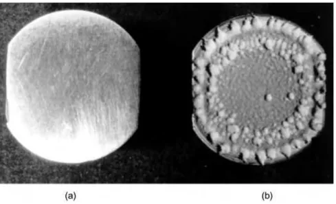
When ultrasonic vibrations are coupled to the solidifying metal structural changes occur including grain refinement, suppression of columnar grain structure, increased homogeneity and reduced segregation. Ultrasonic waves also decrease the viscosity of the molten metal. Additionally, mechanical mixing of the melt due to cavitational collapse and acoustic streaming results in a much reduced temperature gradient across the solidifying charge, and, an increase in the transfer of fine solid parti-cles. In large-scale tests, commercial aluminium alloys have been ultrasonically treat-ed either during continuous casting or in shaptreat-ed casting processes. It was found that ultrasound had little effect on the structure of commercially pure grade aluminium. However, on addition of 0.1 wt% titanium, zirconium and boron carbide, ultrasonic irradiation of the solidifying aluminium resulted in the formation of ultrafine non-dendritic structure of light alloys that improved the plasticity without strength loss. This is very important for crack-free production and processing of large-scale ingots from structural light alloys. Extruded, rolled and forged metal produced from non-dendritic ingots demonstrated an improved plasticity without strength loss and im-proved service characteristics, i. e. low- and multi-cycle fatigue endurance, fracture toughness and corrosion resistance.
!
Processing Applications
Mixing and emulsification
There are a large number of industrial processes which employ cavitation as an energy source for the generation of fine emulsions and dispersions. One of the earliest devices which was developed for this purpose was the so-called liquid whistle (see Chapter 7) and this continues to be used widely. Typical examples of the uses of such whistles include the preparation of emulsion bases for soups, sauces or gravies which consist of a premix of water, milk powder, edible oil and fat together with flour or starch
as thickening agent. After passing through the homogeniser a fine particle size emulsion is generated with a smooth texture. Another example is the production of ketchup as a smooth product with increased thickness and improved taste com-pared with conventional mixers as a result of the complete dispersion of any clumps of tomato pulp.
In the textile industry poor quality dying of fabrics usually can be attributed to the mechanical mixing used. Agglomerates of non-dispersed dye can produce a speckled appearance and uneven mixing may change the shade. By passing the mixture through an ultrasonic homogeniser before use these problems can be overcome.
Extraction
When cavitation bubble collapse occurs near a porous material the jet that is generated is able to force liquid to penetrate the surface. This effect can be utilised to enhance any process that involves either extraction or impregnation of a liquid in a solid.
The classical techniques for the solvent extraction of chemical compounds from vegetable material are based upon the correct choice of solvent and conditions e. g. heating or agitation. A range of commercially important pharmaceuticals, flavours and colourants are now derived from vegetable sources. It has been shown that the solvent extraction of organic compounds contained within the body of plants and seeds is significantly improved by the use of power ultrasound [25].
Impregnation
The benefits of sonochemically forced impregnation of porous materials can be found in a wide variety of technologies. One of these is in the preparation of catalysts of the type often termed ªegg shellº where a catalytically active material is supported on the outside of an inert support material. Thus a catalyst comprising of 1 % (w/w) ruthe-nium on the surface of 4 mm grain size alumina can be made by adsorbing RuCl3from aqueous solution onto the alumina followed by reducing the Ru3+to Ru metal using hydrazine. The resulting catalyst prepared under sonochemical conditions was very different from that prepared conventionally in that there was a greater penetration of the metal into the support with no metal close to the surface [26]. Similar results have been obtained by the same group using catalytic palladium supported on carbon. The same process of sonochemically forced impregnation can be used to enhance the dying of leather. Normal vat dying process involves steeping the leather in an aqueous solution of the dye for a period of time. In the presence of 20 kHz ultrasound (approx. 5 W cm2
processes in leather technology involve liquid treatments and surface penetration there are a number of tanning processes which may be helped by sonication.
Filtration
The requirement to remove suspensions of solids from liquids is common to many industries. This separation can be either for the production of solids-free liquid or to isolate the solid from its mother liquors. Conventionally membranes of various sorts have been employed for these processes ranging from the simple filter pad through semi-permeable osmotic type membranes to those which are used on a size-exclusion principle for the purification of polymeric materials. Unfortunately the conventional methodologies often lead to ªcloggedº filters and, as a consequence, there will always be the need to either replace filters or stop the operation and clean them on a regular basis. The application of ultrasound enables the filtration system to operate more efficiently and for much longer periods without maintenance through two specific effects. Sonication will cause an agglomeration of the fine particles and will supply sufficient vibrational energy to the system to keep the particles partly suspended and therefore leave more free ªchannelsº for solvent elution. Studies of acoustic filtration and separation processes continue to be an important area of applied acous-tics research [28].
Crystallisation
In conventional crystallisation techniques (e. g. in penicillin production), a solution containing materials to be crystallised is super-saturated either by cooling or by eva-poration and is then seeded. The problem with seeding is that it may be initiated non-uniformly and this can result in crystal growth proceeding at different rates at different nuclei sites. The resulting crystals may then show a very broad and uneven crystal size distribution. It is also of considerable practical importance to be able to control the onset of crystallisation in a large-scale production process. Often it occurs in an un-controlled manner simply due to a slight change in external factors such as a tempera-ture or pressure fluctuation.
Ultrasound has proved to be extremely useful in crystallisation processes since it can initiate seeding and control subsequent crystal growth in a saturated or super-cooled medium. This is thought to be due to cavitation bubbles themselves acting as nuclei for crystal growth and to the disruption of seeds/nuclei already present with-in the medium thus with-increaswith-ing the number of nuclei present with-in the medium. Through the correct choice of sonication conditions it is possible to produce crystals of a uniform and designated size which is of great importance in pharmaceutical prepara-tions [29].
Power ultrasound also has an additional property which is particularly beneficial in crystallisation operations namely that the cleaning action of the cavitation effectively stops the encrustation of crystals on cooling elements in the crystallisation vat and thereby ensures continuous efficient heat transfer.
1.4
Ultrasound in Chemistry
Perhaps somewhat surprisingly sonochemistry is not a particularly new subject ± it was under active investigation in the first half of the 20th century. There are literature references to applications in polymer and chemical processes in the 1940's [30, 31]. Despite the fact that a book dealing with sonochemistry was translated from Russian and published in 1964 [32] the major renaissance in the subject has occurred only over the last two decades of the century. This is undoubtedly due to the more general avail-ability of commercial ultrasonic equipment nowadays. In the 1960's the ultrasonic cleaning bath began to make its appearance in metallurgy and chemical labora-tories. Having seen the way in which these baths cleaned soiled glassware and dis-persed immiscible organic solvents in aqueous detergent it was not surprising that chemists began to consider using them to enhance chemical reactivity ± as indeed we ourselves did in the early 70's. A chapter will be devoted to sonochemistry later in this book.
For the majority of chemists an interest in power ultrasound springs from the fact that it provides a form of energy for the modification of chemical reactivity which is different from that normally used e. g. heat, light and pressure. Power ultrasound produces its effectsvia cavitation bubbles. These bubbles are generated during the rarefaction cycle of the wave when the liquid structure is literally torn apart to form tiny voids which collapse in the compression cycle. It has been calculated that pressures of hundreds of atmospheres and temperatures of thousands of degrees are generated on collapse of these bubbles. The physical background for the generation and collapse of such bubbles will be discussed in detail in Chapter 2.
* within the bubble itself which can be thought of as a microreactor
* in the liquid region immediately adjacent to the bubble where the temperatures are
not so great and
* in the immediate vicinity of the bubble where the shockwave produced on collapse
will create enormous shear forces.
The synthetic chemist will be mainly concerned with reactions in solution and the effects of ultrasound in such cases are best summarised in terms of four different reaction types.
Reactions Involving Metal or Solid Surfaces
There are two types of reaction involving metals (1) in which the metal is a reagent and is consumed in the process and (2) in which the metal functions as a catalyst. While it is certainly true that any cleansing of metallic surfaces will enhance their chemical reactivity, in many cases it would seem that this effect alone is not sufficient to explain the extent of the sonochemically enhanced reactivity. In such cases it is thought that sonication serves to sweep reactive intermediates, or products, clear of the metal sur-face and thus present renewed clean sursur-faces for reaction. Other ideas include the possibility of enhanced single electron transfer (SET) reactions at the surface.
Reactions Involving Powders or Other Particulate Matter
Just as with the metal surface reactions described above, the efficiency of heteroge-neous reactions involving solids dispersed in liquids will depend upon the available reactive surface area and mass transfer.
Conventional technology involves agitating and stirring with rotating devices and baffled pipes as the processors of fluids when mixing, reacting or dissolving small and submicron sized particles on an industrial scale. This can take many hours, days or even weeks until the desired properties are obtained. The basic problem with conventional rotational mixing techniques, when trying to disperse solid parti-cles of 10 microns in diameter or smaller in a liquid is that the rate of mixing and mass transfer of these particles through the medium reaches a maximum. In fact the mass transfer coefficientKreaches a constant value of about 0.015 cm s1in water, and liquids of similar viscosity, and cannot be increased any further by increasing the speed of rotational agitation, no matter how large this increase may be. Sonication provides a solution to this problem in that power ultrasound will give greatly en-hanced mixing.
Emulsion Reactions
Ultrasound is known to generate extremely fine emulsions from mixtures of immis-cible liquids. Ultrasonic homogenisation has been used for many years in the food industry for the production of tomato sauce, mayonnaise and other similar blended items. In chemistry such extremely fine emulsions provide enormous interfacial con-tact areas between immiscible liquids and thus the potential for greater reaction be-tween the phases. This can be particularly beneficial in phase transfer catalysis.
Homogeneous Reactions
From the above one might be tempted to attribute ultrasonically enhanced chemical reactivity mainly to the mechanical effects of sonication. However this cannot be the whole reason for the effect of ultrasound on reactivity because there are a variety of homogeneous reactions which are also affected by ultrasonic irradiation. How, for example, can we explain the way in which power ultrasound can cause the emission of light from sonicated water (sonoluminescence), the fragmentation of liquid alkanes, the liberation of iodine from aqueous potassium iodide or the acceleration of homo-geneous solvolysis reactions?
The answer to these questions lies in the actual process of cavitational collapse. The microbubble is not enclosing a vacuum ± it contains vapour from the solvent and any volatile reagents so that, on collapse, these vapours are subjected to the enormous increases in both temperature and pressure referred to above. Under such extremes the solvent and/or reagent suffers fragmentation to generate reactive species of the radical or carbene type some of which would be high enough in energy to fluor-esce. In addition the shock wave produced by bubble collapse or even by the propagat-ing ultrasonic wave itself, could act to disrupt solvent structure which could influence reactivity by altering solvation of the reactive species present.
Tab. 1.2. "# #
* A reaction may be accelerated or less forcing conditions may be required if sonication is applied.
* Induction periods are often significantly reduced as are the exotherms normally associated with such reactions.
* Sonochemical reactions often make use of cruder reagents than conventional techniques.
* Reactions are often initiated by ultrasound without the need for additives.
* The number of steps that are normally required in a synthetic route can sometimes be reduced.