ISSN 1517-7076 artigo 11698, pp.260-269, 2016
Autor Responsável: Otávio Fernandes Lima da Rocha Data de envio: 29/06/2015 Data de aceite: 28/08/2015
10.1590/S1517-707620160001.0024
Influence of upward and horizontal growth
direction on microstructure and microhardness
of an unsteady-state directionally
solidified Al-Cu-Si alloy
Raimundo Lucivaldo Marães de Araújo1, Rafael Hideo Lopes Kikuchi2, André Santos Barros1, Laércio Gouvea Gomes2Daniel Joaquim da Conceição Moutinho2, Fernando de Almeida Gonçalves2, Antonio Luciano Seabra Moreira1, Otávio Fernandes Lima da Rocha1,2
1 Institute of Technology, Federal University of Pará – ITEC/UFPA – 66075-110, Belém, PA
e-mail: ralma@ufpa.br; andre.barros@ufpa.br
2 Federal Institute of Education, Science and Technology of Pará – IFPA – 66093-020, Belém, PA
e-mail: rafael.kikuchi1991@gmail.com, laercio.gomes@ifpa.edu.br, daniel.moutinho@ifpa.edu.br, fernando.goncalves@ifpa.edu.br, otavio.rocha@ifpa.edu.br
ABSTRACT
In order to analyze the effect of the growth direction on dendrite arm spacing (1) and microhardness (HV) during horizontal directional solidification (HDS), experiments were carried out with the Al-3wt.%Cu-5.5wt.%Si alloy and the results compared with others from the literature elaborated for upward directional solidification (UDS). For this purpose, a water-cooled directional solidification experimental device was developed, and the alloy investigated was solidified under unsteady-state heat flow conditions. Thermal parameters such as growth rate (VL) and cooling rate (TR) were determined experimentally and correlations among VL, TR, 1 and HV has been performed. It is observed that experimental power laws characterize 1 with a function of VL and TR given by: 1=constant(VL)-1.1 and 1=constant(TR)-0.55. The horizontal solidification direction has not affected the power growth law of 1 found for the upward solidification. However, higher values of 1 have been observed when the solidification is developed in the horizontal direction. The interrelation of HV as function of VL, TR and 1 has been represented by power and Hall-Petch laws. A comparison with the Al-3wt.%Cu alloy from literature was also performed and the results show the Si element affecting significativaly the HV values.
Keywords: Horizontal directional solidification, Microstructure, Microhardnees, Al-based multicomponent alloys.
1. INTRODUCTION
Aluminum alloys castings have a fundamental role in the metal-mechanics industry. Nowadays these alloys are supplied in a wide range of chemical compositions [1-12]. We highlight the Al-Cu-Si ternary system because of particular outstanding properties such as high mechanical strength, low weight and very good fluidity [3-12]. These qualities make them a good choice for applications in the automotive and aerospace industry. These alloys have attracted much attention of researchers with view to investigating the microstructural evolution, formation of macrosegregation and porosity during the solidification process.
261 Several investigations on directional solidification existing in the literature focusing in the interconnection among solidification thermal variables, microstructure features and mechanical properties are based on samples which were grown by a Bridgman technique. Recently, ÇADIRLI [22] has been investigated the influence of cooling rate and composition on the microhardness (HV) and ultimate tensile strength (σ) of unidirectional solidified Al-Cu alloys during upward steady-state solidification. It has been observed that increasing copper content and cooling rate, microhardness and tensile strength increase, while strain decreases. This author have found relationships given by HV=kλ1−a (a=0.23 to 0.29).
Studies considering unsteady-state solidification deserve special attention since it is the class of heat flow encompassing the majority of industrial solidification processes. However, the vast majority of these works were developed to investigate the microstructural evolution of binary alloys in vertical upward direc-tional solidification [1-6, 8,10-12].
In this sense, considering that studies of unsteady-state directional solidification of aluminum-based multicomponent alloys are still scarce in the literature, the main purpose of this paper is to investigate the influence of upward and horizontal growth direction on microstructure and microhardness of an unsteady-state directionally solidified Al-Cu-Si alloy
2. EXPERIMENTAL PROCEDURE
Experiments was performed with the Al-3wt.%Cu-5.5wt.%Si. The chemical compositions of metals that were used to prepare this alloy are presented in Table 1. Starting melt superheat was standardized at 1.1 times the liquidus temperature (TL) of the alloy analyzed.
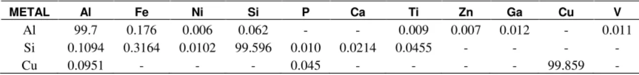
Table 1: Chemical composition of the metals used to prepare the Al-Cu-Si alloy investigated.
METAL Al Fe Ni Si P Ca Ti Zn Ga Cu V
Al 99.7 0.176 0.006 0.062 - - 0.009 0.007 0.012 - 0.011
Si 0.1094 0.3164 0.0102 99.596 0.010 0.0214 0.0455 - - - -
Cu 0.0951 - - - 0.045 - - - - 99.859 -
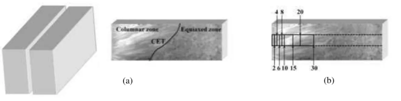
The casting assembly used in solidification experiments is schematized in Figure 1. The directional solidification device was designed to permit heat extraction only through the water-cooled system placed in the lateral mold wall, promoting horizontal directional solidification. The main design criterion was to induce unidirectional heat flow during solidification. A stainless steel mold used had a wall thickness of 3mm, a length of 160 mm, a height of 60 mm and a width of 60 mm. During the solidification process, temperatures at different positions in the alloy samples were measured and the data were acquired automatically. For the measurements, a set of six fine type K thermocouples, arranged as shown in Figure 1, was used. The thermocouples were sheathed in 1.6mmdiameter steel tubes, and positioned at 5, 15, 30, 50, 70 and 90 mm from the heat-extracting surface.
(a)
262 Figure 1: (a) Schematic representation of the horizontal experimental solidification setup: (1) thermocouples, (2) field
logger, (3) computer and data acquisition software, (4) feed water, (5) water container, (6) water pump, (7) rotameter, (8) water inlet, (9) water outlet, (10) directional solidification device and (11) temperature controller; (b) view inside of the solidification device: (12) insulating ceramic shielding, (13) electric heaters and (14) rectangular mold (stainless steel mold - inner wall).
The casting was longitudinally sectioned from the center and the macrostructure was examined, According to scheme shown in Figure 2a. The solution composed of 5 mL of H2O, 60 mL of HCl, 30 mL of HNO3 and 5 mL of HF was used to reveal the macrostructure. Selected transverse sections (perpendicular to the growth direction) of the directionally solidified specimens at 2, 4, 6, 8, 10, 15, 20, and 30 mm from the metal-mold interface were polished and etched with a solution of 5% of NaOH in water for micrograph examination. Figure 2b represents the macrostructure revealed to alloy analyzed in this study and removed positions of the ingot to microstructural analysis. Image processing system Olympus BX51 and Image Tool (IT) software were used to measure primary arm spacing (about 20 independent readings for each selected position, with the average taken to be the local spacing) and their distribution range. The method used for measuring the primary arm spacing on the transverse section was the triangle method [10]. Measurement of the primary dendritite arm spacings on the transverse section was carried out using the triangle method [25,28]. The triangle is formed by joining the three neighboring dendrite centers, the sides of the triangle
corresponding to λ1, as shown in Figure 3. Microstructures of directionally solidified samples were also
characterized using a scanning electron microscope (SEM Shimadzu, VEGA 3 SBU TESCAM) coupled to an energy dispersion spectrum (EDS AZTec Energy X-Act, Oxford).
The mechanical properties of any solidified material are usually determined using hardness, tensile, and ductility tests [13]. The microhardness measurements in this work were performed using a Shimadzu HMV-2 model hardness measuring test device using a 50 g load and a dwell time of 10 s. The adopted Vickers microhardness values were the average of at least 20 different measurements on the transverse section of each sample. The experimental results of each microhardness value as a function of both the position and primary dendritic arm spacing are represented by a variation between the minimum and maximum limit obtained from 20 different measurements.
Figure 2: Schematic representation of removal of ingot samples for macrostructural and microstructural analysis: (a)
longitudinal cut of the ingot and revelation of solidification macrostructure and (b) cutting positions of the samples for measurement of primary spacings.
263 Figure 3: Triangle method for measurement of 1 values: (a) dendritic microstructure obtained in this work, showing the
distances between primary arms centers forming a triangle and (b) schematic representation of the method.
3. RESULTS AND DISCUSSION
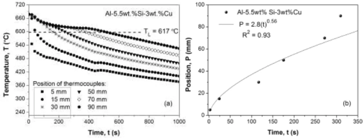
Experimental cooling curves for six thermocouples inserted into the casting during solidification of the alloy investigated in this study are shown in Figure 4.
Figure 4: (b) Temperature profiles obtained for Al-Cu-Si alloy analyzed in this work with 10% of superheat and (b)
liquidus isotherm experimental position of from the metal-mold interface as function of time.
The primary dendritic arm spacings are dependent on solidification thermal parameters such as VL and TR. In order to determine more accurate values of these parameters, the results of experimental thermal analysis, shown in Figure 4a have been used to generate a plot of position from the metal/ mold interface as a function of time corresponding to the liquidus front passing by each thermocouple. This methodology has been detailed in our recently published articles [7-14]. A curve fitting technique on such experimental points has generated a power function of position as a function of time (see Figure 4b). The derivative of this function with respect to time has yielded values for VL, shown in Figure 5a. Figure 5b shows the TR profile, which was calculated by considering the thermal data recorded immediately after the passing of the liquidus front by each thermocouple [7-14].
Figure 5: Experimental results of thermal parameters analyzed in this study: (a) growth rate as a function of position
from the metal/mold interface and (b) cooling rate as a function of position from the metal/mold interface.
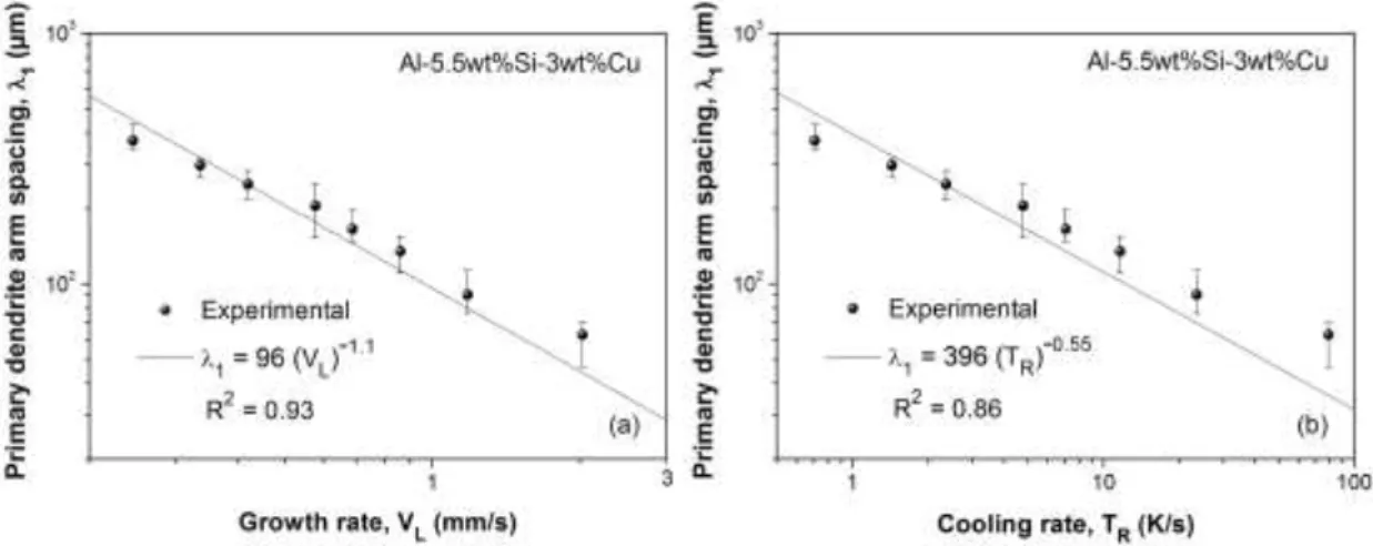
264 resistance of the solidified layer with distance from the heat-extracting surface. This influence of the solidification thermal variables translates to the observed experimental values of 1 as shown in Figure 6, where average values with the standard variation of are plotted as a function of VL and TR. It is observed in Figures 6a and 6b that power laws equal to -1.1 and -0.55 characterize the experimental variation of primary spacing with growth rate and cooling rate, respectively, i.e, λ1 = 96(VL)-1.1 and λ1 = 396(TR)-0.55. This is in
agreement with observations reported by ROCHA et al. [10], PERES et al. [5], CARVALHO et al. [7],
CRUZ et al. [15] BARROS et al. [13] COSTA et al. [12] and GOMES [16] that exponential relationships
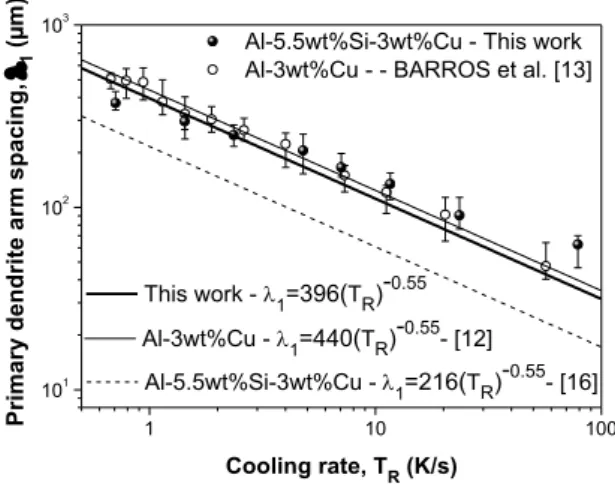
and λ1 = constant(VL)-1.1 and λ1 = constant(TR)-0.55 best generate the experimental variation of primary den-dritic arms with VL and TR along the unsteady-state solidification of Al-Cu, Al-Si, Al-Sn, Al-Cu, Al-Cu-Si and Al-Cu-Si alloys, respectively. With a view to analyzing the effect of Si element in binary Al-3wt.% Cu alloy as well as the influence of growth direction on the length scale of the dendritic microstructure (1) the average, maximum and minimum values of the correlation between 1 and TR of this work are plotted in Figure 7 and compared with the experimental equations obtained by BARROS et al. [13] and GOMES [16],
whose works have been developed to horizontal and upward directional solidification, respectively. When
comparing the mean values of λ1 obtained in the present study with those reported recently by BARROS et
al. [13] (see Figure 7) similar growth laws can be observed, i.e., the addition of Si in the Al-3wt.%Cu alloy
seems to have no noticeable effects on reduction in the length scale of the 1 values during horizontal directional solidification. On the other hand, considering the experimental law 1 = f (TR) in both growth configurations (upward and horizontal), the experimental spectrum of λ1 values of the Al-3wt.%Cu-5.5wt.%Si alloy is higher for the horizontally solidified casting than that verified by GOMES [16] during upward directional solidification. It is usually assumed that the effect of the natural convection in the liquid can be neglected during upward vertical solidification [5, 17]. In contrast, for horizontal directional configuration the solute-enriched liquid located in the interdendritic regions and ahead the dendrite tips, induced thermosolutal convection since it is denser than the bulk liquid [12]. COSTA et al. [12] reported that
the absence of melt convection during upward solidification of Al-Cu-Si alloys forces the rejected Si to be confined in the interdendritic regions, thus raising the constitutional supercooling, leading to the onset of tertiary. These tertiary branches have a growth character similar to that of the primary branches and their presence will provide new primary arms [18] grown from the secondary branches. This, as a consequence, will reduce the interdendritic spacing between primary arms, as can be observed in the present investigation.
Figure 6: (a) Primary dendrite arm spacing as a function of growth rate and (b) primary dendrite arm spacing as a
265 Figure 7: Primary dendrite arms spacing as a function of cooling rate: Comparison among the results obtained in this
work with those obtained by BARROS et al. [13] and GOMES [16].
Typical solidification microstructures of transverse section of the samples at 10 and 30 mm from met-al/mold interface, showing the primary dendrite arms are shown in Figure 8. It can be characterized by α-Al phase of dendritic morphology, with Si particles in the aluminum-rich matrix as well distributed along the interdendritic regions in the eutectic mixture interlinked with Al2Cu intermetallic phase developing the mi-crostructure α-Al + Al2Cu + Si. Figure 9 depicts some detailed images by SEM-EDS mapping. It can be ob-served that the points 1, 2, 3, 4 and 5 indicate the place where microanalysis by SEM-EDS mapping have been carried out, and the arrows represent the microstructural phases present in the analyzed alloy. This is confirmed the presence of Si particles in the interdendritic regions very close to the Al2Cu intermetallic phas-es, as shown in the microanalysis of points 4 and 5.
P= 10 mm VL = 0.6 mm/s
TR = 4.8 K/s
λ 1 = 205 µm
P = 30 mm VL = 0.24 mm/s
TR = 0.71 K/s
λ 1 = 373 µm
Figure 8: Solidification microstructures of obtained for the Al-Cu-Si alloy analyzed in this work.
1 10 100
101 102 103
This work - 1=396(TR)-0.55
Al-3wt%Cu - 1=440(TR)-0.55- [12] Al-5.5wt%Si-3wt%Cu - This work Al-3wt%Cu - - BARROS et al. [13]
Al-5.5wt%Si-3wt%Cu -1=216(TR)-0.55- [16]
Cooling rate, TR (K/s)
P rim a ry d e n d rit e a rm s p a c in g , 1 ( µ m ) pt. 1
Al2Cu pt. 4
pt. 3
pt. 2 Si
266 Figure 9: (a) Typical SEM micrograph at position of 10 mm from metal/mold interface and (b) EDS patterns and the
corresponding chemical composition.
Expressions correlating the mechanical behavior with features of the as-solidified microstructure can enable metal production industries to optimize the cast alloy properties. KAYA et al. [21] reports that
micro-hardness analysis seems to be one of the easiest and most straightforward techniques of monitoring mechani-cal properties. Figure 10 shows the dependence of the microhardness (HV) on the distance (P) from the met-al-mold interface (Figure 10a) and λ1 (Figures 10b and 10c) for the alloy investigated. It is observed that the Figures 10b and 10c depicts the evolution of HV with the measured primary dendrite arm spacings along the casting length. The microhardness is higher for smaller dendritic spacings (at regions close to the cooled sur-face of the casting). This can be noted that the microhardness results decrease with an increase in the 1 val-ues, and the dependence of HV on 1 and 1-1/2 can also be represented by power and Hall-Petch type equa-tions given by HV = 215(λ1)-0.16 and HV = 64+401(λ1)-1/2, respectively. Figure 10 compares also the power-type experimental law obtained for the ternary Al-3wt.%Cu-5.5wt.%Si alloy of the present study with the experimental laws proposed by BARROS et al. [13] for the binary Al-3wt.%Cu alloy solidified under the
same conditions of this study. It can be seen that the addition of Si in binary Al-Cu alloy increases HV values in the ternary Al-Cu-Si alloy. Figure This is verified in Fugure 9 the presence of primary silicon isolated par-ticles dispersed in eutectic-matrix, which appear to be responsible for the high hardness noted in Al-3wt.%Cu-5.5wt.%Si of this work.
pt. 5
Point Weigth (%)
Al Cu Si Fe
1 97.5 1.28 1.22 -
2 31.34 57.18 11.48 -
3 26.6 61.55 8.05 3.8
4 30.93 1.4 67.67 -
5 7.47 0.98 91.56 -
(a)
267 Figure 10: Microhardness evolution for the analyzed alloy as a function of (a) liquidus isotherm position (P), (b) 1, and
(c) 1-1/2.
268 Figure 11: Microhardness evolution for the analyzed alloy as a function of (a) growth rate (VL) and (b) cooling rate (TR).
4. CONCLUSION
The following major conclusions can be drawn from this study, where Al-3wt.%Cu-5.5wt.%Si alloy has been directionally solidified under unsteady-state heat flow conditions:
(a) Under transient horizontal solidification conditions the primary dendritic spacings were observed to decrease when tip growth rate and cooling rate are increased.
(b) Relations between λ1 with the growth rate and cooling rate were obtained by the following experimental laws: λ1=96(VL)-1.1 and λ1=396(TR)-0.55.
(c) The microhardness (HV) dependency on the thermal parameters and microstructure (λ1) can be represented by power and Hall-Petch-type relationships given by HV = 101(VL)0.14, HV = 85(TR)0.06, HV = 215(λ1)-0.16 and HV = 64+401(λ1)-1/2.
(d) The presence of Si element in the Al-Cu-Si alloy investigated in this study allowed to obtain smaller primary dendrite arm spacing in comparison with the binary A-Cu alloy (BARROS et al. [13]) as well as
Si added in the Al-Cu alloy to form the ternary Al-Cu-Si alloy has increased the microhardness values. (e) This study may contribute to for liquid metal processing in industry aiming at designing of a required
alloy microstructure and mechanical properties, considering a better understanding of the thermal parameters and processes occurred in the Al-Cu and Al-Cu-Si alloys.
5. ACKNOWLEDGEMENTS
The authors acknowledge the financial support provided by IFPA (Federal Institute of Education, Science and Technology of Pará), UFPA (Federal University of Pará), CAPES (Coordination of Superior Level Staff Improvement) and CNPq (the Brazilian Research Council), Brazil.
6. BIBLIOGRAPHY
[1]BOUCHARD, D., KIRKALDY, J.S., “Prediction of dendrite arm spacings in unsteady and steady state
heat flow of unidirectionally solidified binary alloys”, Metallurgical and Materials Transactions B, v.28, pp.
651-663, 1997.
[2] HUNT, J.D., LU S.Z., “Numerical modeling of cellular/dendritic array growth: spacing and structure
predictions”,Metallurgical Materials Transactions A, v.27, pp. 611-623, 1966.
[3] FERREIRA, I.L., LINS, J.F.C., MOUTINHO, D.J., et al., “Numerical and experimental investigation of
microporosity formation in a ternary Al Cu Si alloy”,Journal of Alloys Compounds, v. 503, pp. 31-39, 2010.
[4] RAPPAZ, M., BOETTINGER, W.J., “On dendritic solidification of multicomponent alloys with unequal
liquid diffusion coefficients”,Acta Materialia, v.47, pp. 3205-3219, 1999.
[5] PERES, M.D., SIQUEIRA, C.A., GARCIA, A., “Macrostructural and microstructural development in Al-Si alloys directionally solidified under unsteady-state conditions”,Journal of Alloys and Compounds, v. 381,
pp. 168-181, 2004.
[6] EASTON, M., DAVIDSON, C., JOHN, D., “Effect of alloy composition on the dendrite arm spacing of
269 [7] CARVALHO, D.B., MOREIRA, A.L., MOUTINHO, D.J., et al., “The columnar to equiaxed transition of
horizontal unsteady-state directionally solidified Al-Si alloys”, Materials Research, v. 17, pp. 498-510, 2013. [8] GOMES, L.G., ROCHA, O.L., MOUTINHO, D.J.C., et al., “The Growth of Secondary Dendritic Arms
in Directionally Solidified Al-Si-Cu alloys: a comparative study with binary Al-Si alloys”, Applied
Mechanics and Materials, v. 719-720, pp. 102-105, 2015.
[9] SILVA, J.N., MOUTINHO, D.J., MOREIRA, A.L., et al., “The columnar to equiaxed transition during
the horizontal directional solidification of Sn-Pb alloys” Journal of Alloys and Compounds, v.478, pp.
358-366, 2009.
[10] ROCHA, O.L., SIQUEIRA, C.A., GARCIA, A., “Heat flow parameters affecting dendrite spacings
during unsteady-state solidification of Sn-Pb and Al-Cu alloys”, Metallurgical and Materials Transactions A,
v. 34, pp. 995-1006, 2003.
[11] ROCHA, O.L., GOMES L.G., MOUTINHO, D.J.C., et al, “The columnar to equiaxed transition in the
directional solidification of aluminum based multicomponent alloys”, Revista Escola de Minas, v. 68, pp.
85-90, 2015.
[12] COSTA T.A., MOREIRA, A.L., MOUTINHO, D.J., et al., “Growth direction and Si alloying affecting
directionally solidified structures of Al-Cu-Si alloys”, Materials Science and Technology. v. 31,
pp.1103-1112, 2015.
[13] BARROS, A.S., MAGNO, I.A., SOUZA, F.A., et al., “Measurements of microhardness during transient
horizontal directional solidification of Al-rich Al-Cu alloys: effect of thermal parameters, primary dendrite arm spacing and Al2Cu intermetallic phase”, Metals and Materials International, v. 21, pp. 429-439, 2015.
[14] DIAS FILHO, J.M., KIKUCHI, R.H., COSTA, T.A.P.S., et al., “Influência das variáveis térmicas sobre
os espaçamentos dendríticos terciários durante a solidificação direcional horizontal da liga Al-6%Cu”,
Matéria, v. 20, pp.47-63, 2015.
[15] CRUZ, K.S, MEZA, E.S, FERNANDES, F.A.P, et al., “Dendritic arm spacing affecting mechanical
properties and wear behavior of Al-Sn and Al-Si alloys directionally solidified under unsteady-state conditions”, Metallurgical and Materials Transactions A, v. 41, pp. 972-984, 2010.
[16] GOMES, L.G., Microestrutura Dendrítica, Macrossegregação e Microporosidade na Solidificação de
Ligas Ternárias Al-Si-Cu. PhD Thesis, UNICAMP, Campinas, SP, Brasil, 2012.
[17] MAGNUSSON, T., ARNBERG, L., “Density and solidification shrinkage of hypoeutectic aluminum-silicon alloys”,Metallurgical and Materials Transactions A, v. 32, pp. 2605- 2613, 2001.
[18] CURRERI, P.A., LEE, J.E., STEFANESCU, D.M., “Dendritic solidification of alloys in low gravity”,
Metallurgical Transactions A, V. 19, pp. 2671-2676, 1998.
[19] PARK, M., “Effect of Si addition on the precipitation of Al2Cu-phase in Al-Cu-Si thin films”, Journal of
Materials Science, v. 40, pp. 3945-3949, 2005
[20] KARAKÖSE, E., KESKIN, M., “Structural investigations of mechanical properties of Al based rapidly
solidified alloys”, Materials and Design, v. 32, 4970-4979, 2011.
[21] KAYA, H., ÇADIRLI, E., BÖYÜK, U., et al., “Variation of microindentation hardness with
solidification and microstructure parameters in the Al based alloys”, Applied Surface Science, v. 255,
pp.3071- 3078, 2008
[22] ÇADIRLI, E., “Effect of solidification parameters on mechanical properties of directionally solidified