Ultrasonic assessment and inite element modelling
of thermo-mechanical damage in mortar
Avaliação ultrassônica e modelagem com elementos
initos do dano termomecânico em argamassa
Abstract
Resumo
Experiments were conducted to evaluate degradation of mechanical properties in mortar specimens subjected to thermal and mechanical load-ing. Ultrasonic pulse velocity was used to assess changes in the microstructure of the specimens due to thermal and mechanical loads applied
separately. Both longitudinal and transverse waves were used. At irst the specimens were tested in the undamaged stage, and then they were also tested after their exposure to a non-uniform thermal load only, inally, mechanical loading was applied until peak load. A inite element model
was used in the dynamic simulation of pulses propagation. Results showed that mortar mix with a larger proportion of coarser aggregates is more sensitive to mechanical loading after exposure to heat than mortar with lesser and smaller aggregate contents. Mortar mix design with less and
iner aggregate did not show a reduction in the pulse velocity as intense as the mortar with more coarse aggregate, which indicates a less severe difuse microcracking.
Keywords: ultrasonic testing of concrete, thermo-mechanical damage, uniaxial compressive loading, inite element modelling, nondestruc -tive testing.
No presente artigo, a degradação das propriedades mecânicas de corpos de prova de argamassas sujeitos a carregamentos térmicos e mecânicos foi avaliada experimentalmente. A velocidade do pulso ultrassônico foi usada para avaliar mudanças na microestrutura dos corpos de prova devido ao carregamento térmico e ao carregamento mecânico separadamente. Pulsos longitudinais e transversais foram usados na avaliação. Inicialmente, foram testados corpos de prova sem qualquer dano; posteriormente, os testes foram repetidos apos a aplicação de um carregamento térmico não uniforme. Na terceira etapa dos testes, os corpos de prova foram avaliados com ultrassom durante a aplicação de carregamento mecânico uniaxial
até a ruptura. Uma modelagem numérica com elementos initos foi usada no estudo da propagação dos pulsos. Os resultados mostraram que o
traço de argamassa com maior teor de agregados graudos é mais suscetível ao dano mecânico, após a aplicação do carregamento térmico, que
a argamassa com menor teor de agregados e agregados mais inos. A argamassa com menor teor quantidade de agregados e mais ina granulo -metria não apresentou redução na velocidade do pulso ultrasônico tao intensa quanto a argamassa com agregado mais graúdo, o que indica uma
microissuração menos severa.
Palavras-chave: ensaio ultrassônico para concreto, dano termomecânico, compressão uniaxial, elementos initos, ensaios não destrutivos.
a Dept. of Civil Engineering, Univ. of Colorado Denver, Denver, CO, USA. Dept. of Civil Engineering, Federal University of Pernambuco, Recife, PE, Brazil.
Received: 06 Apr 2016 • Accepted: 12 Dec 2016 • Available Online: 27 Jul 2017
C. L. NOGUEIRA a
1. Introduction
When subjected to mechanical or thermal loading materials like mortar and concrete undergo severe microcracking and concomi -tant degradation of their elastic properties. Damage in concrete due to thermal loading alone can be easily characterized, even for tem-peratures as low as 150oC, with microscopic imaging, in the form of
visible opening around the aggregates [7, 28]. The openings directly
afect the propagation of ultrasonic elastic waves and reduces pulse
velocity in the thermally damaged concrete [6, 19, 29]. Mathematical
modeling of such form of difuse damage still challenges the most
recent developments of continuum damage mechanics theories and fracture mechanics. As a consequence, for the assessment of
dam-age due to ire in rehabilitation projects the engineer has to rely upon
nondestructive evaluation (NDE) techniques.
The most remarkable advantages of NDE techniques when com -pared to traditional destructive and semi-invasive techniques are: their applicability for in situ inspection of structures and their non-invasive nature [21]. Among the available NDE techniques (radar, schmidt hammer, tomography, thermography, acoustic emission, etc.), the ones based on ultrasonic pulses propagation have proved to be more suitable for the assessment of distributed damage (e.g.
microcracking due to thermal-mechanical damage). Because of its
relatively low cost and capacity of revealing microscopic changes in the inspected material, ultrasonic testing has been applied to evaluate mechanical [16, 20, 25], thermal [3, 5-8, 10, 12, 28, 29], and environmental [24] damage in concrete. Concrete’s intrinsi-cally complex nature has its characteristics depending on many factors, in such a way that theoretical models are of little help in the analysis of concrete performance after exposure to damage.
Some complex phenomena associated with difuse thermal dam
-age, such as post-ire-curing process [29], are not yet completely
understood, neither extensively evaluated until now. In this
sce-nario, ultrasonic pulse velocity has been used to evaluate difuse damage due to ire and to estimate residual compressive strength even in ield applications [5, 7]. Traditionally, velocity of ultrasonic
pulses traveling through concrete members has been the most reli-able parameter used in ultrasonic methods.
In the experiments described in this paper, in order to enhance the understanding of damage processes due to thermal and mechani-cal loading in cement-based materials, both longitudinal and trans-verse ultrasonic waves were used to evaluate two mortar mixes
with diferent aggregate proportions of the same type (crushed rock). The variation in the ultrasonic velocity due to thermal loading
and due to the application of mechanical load were analyzed
ex-perimentally and with a inite element model. Experimental results
showed that variations in the ultrasonic pulse speed are greatly
inluenced by aggregate proportions and size distribution, indicat -ing that these parameters play an important role in the severity of damage when cement-based materials are exposed to the same thermo-mechanical loads.
1.1 Research signiicance
In the last decades, due to concerns with ire-hazard mitigation, several construction codes in diferent countries have adopted es
-timates of thermal-load deleterious efects on concrete structural
properties, e.g., ABNT-NBR15.200/2012, ACI 216.1-07, ASCE, Eurocode, and CEB [10]. Theoretical evaluation of the residual re-sistance of concrete subjected to damage as a result of exposure to high temperatures in conjunction with mechanical loading is yet beyond the most recent developments in damage mechanics and fracture mechanics theories. Nonetheless, nondestructive test-ing with ultrasonic pulses can provide reliable information about
Figure 1
cement-based materials properties regardless of the complexity
of the difuse phenomena that take place during loading (either
thermal or mechanical). In addition, a growing demand for reliable
nondestructive methods to investigate concrete has taken place in
the last decade, mainly because of the need to evaluate damaged
concrete structures with difuse (e.g., environmental, mechanical,
thermal damage) or localized damage (cracks, voids, etc.). The ob
-jective of the experiments and analysis described in this work is to
evaluate the applicability of ultrasonic pulse velocity method (longi-tudinal and shear waves) in the assessment of thermo-mechanical
damage in mortar with diferent mixes. The experimental program
also assesses how aggregate total amount and aggregate size
dis-tribution afect damage due to thermal and mechanical loads. The
results presented can be used as a reference in the analysis of
other cement-based granular materials with ine or coarse aggre
-gates. A inite element model was used to evaluate ultrasonic pulse
longitudinal and shear propagation velocities in order to validate the experimental results obtained.
2. Materials and experimental setup
Two prismatic mortar specimens (dimensions: 76.2 x 76.2 x 152.4
mm, 3 x 3 x 6 in) with diferent mixes were used in the experiments.
Initially, the ultrasonic pulse velocity in the unloaded specimens was measured. Each specimen was then exposed to two heat
sources at diferent temperatures in the two opposite sides until a
steady state was reached. The specimens were then exposed to the steady state temperature for one hour and, after cooling, tested with ultrasound pulse velocity. After that, the specimens were uni-axially loaded until failure. During the application of uniaxial load ultrasonic pulses were recorded and – again – analyzed with re-gard to changes in velocity.
2.1 Testing equipment
Two heat guns were used in the application of the thermal loading and a digital thermometer was used to read the temperatures on the specimens (Figure 1). A universal MTS loading machine with a
maxi-mum capacity of 484 kN (110 kips) was used for the application of the
mechanical load in the specimens. Load is measured using internal load cells and calibrated so that the output voltage determines the ax-ial load. External axax-ial and lateral LVDTs (linear variable displacement transducer) were used to measure the deformations on the speci-mens. Schaevitz model 200 HR-DC LVDTs, with a range of 10.16 mm (0.4 in) corresponding to an output voltage of –10V to 10V, were used to measure the axial deformations. For the lateral deformation Schaevitz model 500 HR-DC LVDTs were used: range of 25.4 mm (1 in) and same output voltage. During the experiments load and LVDTs output were recorded in time intervals of 1 second. Figure 2 schemati-cally shows the position of the loading platens, specimen, and LVDTs. The ultrasonic instrumentation is composed of three parts: the ultra-sonic longitudinal and transverse wave transducers, a pulser/receiv-er card, and an oscilloscope card assembled in the computpulser/receiv-er that records the output from the pulser/receiver card. Both longitudinal and transverse wave transducers have a diameter of 25.4 mm (1.0 in). The longitudinal wave transducer, which operates at a frequency
of 500 kHz, and the transverse wave transducer, that operates at 250 kHz, were applied according to Figure 1: both pairs were glued
along the sides of each specimen, at 1/3 (transverse wave transduc-ers) and 2/3 (longitudinal wave transductransduc-ers) of the specimen height. All ultrasonic velocity measurements, both in undamaged and dam-aged specimens, where done according to Figure 1. The transduc-ers provide heavily damped broadband performance, producing im-proved signal-to-noise in attenuating and scattering materials. In the
experiments – Figure 3 – the transducers were irmly attached to the
Figure 2
Schematic representation of the position of the
loading platens, specimen, LVDTs, and thermal
load temperatures
Figure 3
specimens using plastic supports glued to their sides, a thin layer of couplant was provided between the transducer surface and the grinded sides of the specimens. The pulser/receiver card allows the
user to control gain, high-pass and low-pass ilters in order to obtain
the cleanest signal possible. The oscilloscope card reads the signal
from the pulser receiver and stores it in a ile.
2.2 Test specimens
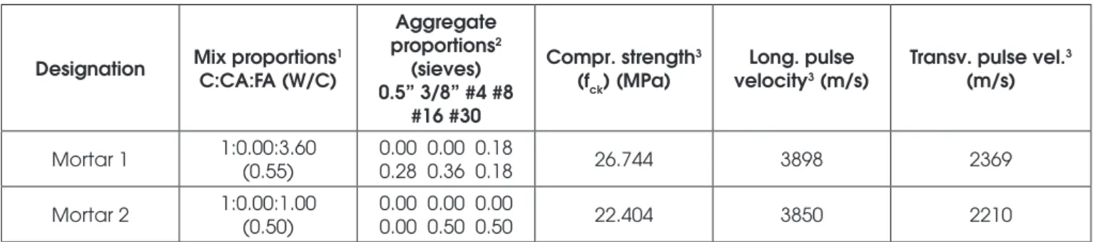
Mix proportions of the two specimens used in the experiments are shown on Table 1. Both specimens were prepared with Type
1 Portland cement and kept in the fog room for 28 days until they were tested. The specimens were cast in steel molds and kept
in ambient conditions for one day, then were put in the fog room,
after being taken from the molds. For the irst mortar mix (Table 1 –
Mortar 1) aggregate proportions were distributed in accordance to grading requirements of ASTM Standards (column 3 – aggregate
proportions, sieves), the ratio cement : aggregate (ine aggregate
only) used was 1:3.60. The second mortar mix – Mortar 2 – has a design with equal weight of cement and aggregate (1:1.00), and aggregate was distributed with 50% retained in sieve #16 (1.18mm) and 50% retained in sieve #30 (0.60mm). Mix 1 was de-signed to represent usual sieve distributions found in mortars and
in concretes, while mix 2, with an unusual distribution and very ine aggregates, was used as a reference to evaluate deleterious efect
of standardized aggregate distribution while thermal loading was
applied (as aforementioned cracking around coarser aggregates
has been reported in microscopic analysis of thermally-damaged concrete [7, 28]). A comparison of the ultrasonic pulse velocities in both mixes, after exposure of specimens to the same thermal and
mechanical loads, will then relect the deleterious cracking efect
in the cement paste–aggregates interface due to the use of more
and coarser aggregate contents. Compressive strength and pulse velocities for the two mixes (undamaged specimens) are also pre-sented in Table 1. As also shown in Table 1, ultrasonic velocities
in Mortar 1 and Mortar 2 are not very diferent, nonetheless com
-pressive strengths are almost 20% diferent (Mortar 2 – 22.4MPa,
Mortar 1 – 26.7MPa).
Specimens were 76.2 x 76.2 x 152.4 mm (3 x 3 x 6 in) prismatic samples with two opposite faces carefully grinded for the
attach-ment of the transducers. On each side a longitudinal and a trans-verse transducer were positioned precisely aligned with the corre-sponding transducer on the opposite side. Grinding the specimens also ensured good parallelism of the specimen sides where the transducers were attached. The grinded sides were then exposed to the heat guns until a constant temperature of 50oC was reached
on the left surface (sender transducer) and a temperature of 120oC
was attained on the right side (Figure 1 and Figure 3). This steady
state was kept constant for one hour and a linear variation of tem -perature was assumed to exist between the opposite sides (for larger specimens and higher temperatures – 600oC – a period of 2
hours was proven to be enough to reach steady state [29]). After cooling, the specimens were attached to the LVDTs and transduc-ers and positioned in the loading frame (Figure 3). After application of a small load – approximately 1% of the maximum load – LVDTs were adjusted to operate in the most accurate region of their cali-bration curves.
3. Mechanical behavior of concrete
exposed to high temperatures
When exposed to high temperatures concrete undergoes several
phenomena (thermal expansion, drying shrinkage, release of gas
-es, difusion of water, increase in pore pressure, etc.) that will ulti -mately lead to a degradation of its elastic properties. This degrada-tion of the mechanical properties of concrete after being exposed
to high temperatures is considered to be a consequence of difuse microcracking [3] which occur mostly around the aggregates [7,
28]. Experimental studies have shown that the modulus of elas-ticity of concrete decreases with the increase of the temperature according to the following relation [3]:
(1)
here To=900oC.
Figure 4.a show the variation of the modulus of elasticity for
con-cretes with diferent aggregate types. Poisson’s ratio shows a
slight increase with temperature up to approximately 50oC (Figure
4.b). After that point Poisson’s ratio shows a fast decrease in its
Table 1
Mix proportions and mechanical properties
Designation Mix proportions1
C:CA:FA (W/C)
Aggregate
proportions2
(sieves) 0.5” 3/8” #4 #8
#16 #30
Compr. strength3
(fck) (MPa)
Long. pulse
velocity3 (m/s)
Transv. pulse vel.3
(m/s)
Mortar 1 1:0.00:3.60 (0.55)
0.00 0.00 0.18
0.28 0.36 0.18 26.744 3898 2369
Mortar 2 1:0.00:1.00 (0.50)
0.00 0.00 0.00
0.00 0.50 0.50 22.404 3850 2210
1 Fractions in weight: C–cement, CA–coarse aggregate, FA–fine aggregate, W/C–water/cement ratio;
2 Crushed rock aggregate, retained fractions in weight; sizes in mm: 12.7, 9.53, 4.75, 2.36, 1.18, and 0.60;
value with the increase in the temperature. Curing conditions are
one of the most inluential factors in the variation of concrete den -sity with increase in temperature. Concretes cured at 20oC with a
relative humidity of 65% are relatively stable with respect to their density up to temperatures of 600oC (Figure 4.c). All three factors
mentioned above, namely, modulus of elasticity, Poisson’s ratio,
Figure 4
Degradation of cement-based materials properties at high temperatures: (a) Variation of the modulus
of elasticity of Portland concretes with various aggregates as a function of the temperature (Cruz, 1966
[4]); (b) Variation of the Poisson’s ratio of Portland cement concrete (Marechal, 1972 [15]); (c) Effect of
temperature in the density of concrete (Schneider, 1982 [23])
Table 2
Ultrasonic wave velocities measured during the experiments
Mortar 1 Mortar 2
Stage
Longitudinal pulse velocity
(m/s)
Transverse pulse Stage
Longitudinal pulse velocity
(m/s)
Transverse pulse
Undamaged1 3898 2369 Undamaged1 3850 2210
Thermal
damage 3896 2342
Thermal
damage 3626 2107
Mechanical damage2
(67.45%3)
3588 2276
Mechanical damage2
(86.13%3)
3606 2084
Mechanical damage2
(77.01%3)
3459 2218
Mechanical damage2
(89.27%3)
3595 2075
Mechanical damage2
(88.18%3)
(-) 2057
Mechanical damage2
(93.87%3)
3582 2056
Mechanical damage2
(92.67%3)
3275 (-)
Mechanical damage2
(95.96%3)
3566 2041
Mechanical damage2
(98.06%3)
3195 (-)
Mechanical damage2
(99.02%3)
3536 1995
1 Undamaged stage, i.e. before exposed to heat or mechanical load; 2 Mechanical load after the exposure to heat;
3 Percentages of the peak load;
and density, are inluential in the pulse propagation velocity. From
linear isotropic elasticity, the longitudinal and transverse velocity can be calculated from:
(2a)
(2b)
where E0, ρ0, and ν0 are the values of the modulus of elasticity, the density, and the apparent Poisson’s ratio, respectively, of the initial unloaded stage. Therefore, through equations 2.a and 2.b, pulse
velocity measurements are very well suited for monitoring difuse
damage in concrete due to exposure to high temperature. In ad-dition, velocity measurements can be also used in the formulation of mechanical damage indicators [16]. It is important to empha-size that velocity measurements based on through-transmission ultrasonic applications (the pulse crosses the specimens from one side – sender transducer – to the other – receiver transducer; Fig-ure 4) are not only very reliable and repeatable (pulses can be easily applied several times), but also easily and promptly appli-cable to most existing structures. For these reasons, this type of ultrasonic application has been successfully used to assess
dam-age in structures exposed to ire [3, 5, 8], to assess other kinds of difuse damage [16, 24, 25], and can even be applied to evalu
-ate and characterize concretes [14, 27] and to estim-ate grain-size distribution in cement-based materials [17, 18]. Other techniques to assess thermal damage, based on nonlinear ultrasound and
resonance have been so far applied to small samples [19, 28, 29]; unfortunately extraction of samples implies not only damage to the real structures, but also damage and perturbation of the extracted portion (unload, stress release, cracks, etc.), for this reason, ultra-sonic testing based on through-transmission techniques are more
adequate for assessing ire-damaged concrete.
4. Experimental results
Transverse and longitudinal digital signals were recorded at three stages: (1) undamaged specimen – before the application of ther-mal loading; (2) after the application of therther-mal loading; and (3) during the application of the mechanical loading – in the nonlinear part of the concrete loading curve, i.e., after approximately 70% of
the maximum load until peak load. In order to improve the
signal-to-noise ratio, the signals were averaged.
In the experiments, the increase in the lateral dimensions of the
specimens, due to Poisson’s efect, was taken into account in the
velocity measurements. The travel time was determined as the
diference between (a) the zero-crossing of the ultrasonic pulse
recorded with the transmitting and receiving transducers glued to-gether with a thin layer of couplant, and (b) the pulse recorded after attaching the transducers to the specimen sides – then the
Table 3
Ultrasonic wave velocities decrease
Mortar 1 Mortar 2
Stage
Longitudinal pulse velocity
decrease1
Transverse pulse velocity
decrease1
Stage
Longitudinal pulse velocity
decrease1
Transverse pulse
velocity decrease1
Thermal
damage -0.05 -1.14
Thermal
damage -5.82 -4.66
Mechanical damage2
(67.45%3)
-7.95 -3.92
Mechanical damage2
(86.13%3)
-6.34 -5.70
Mechanical damage2
(77.01%3)
-11.26 -6.37
Mechanical damage2
(89.27%3)
-6.62 -6.11
Mechanical damage2
(88.18%3)
(-) -13.17
Mechanical damage2
(93.87%3)
-6.96 -6.97
Mechanical damage2
(92.67%3)
-15.98 (-)
Mechanical damage2
(95.96%3)
-7.38 -7.65
Mechanical damage2
(98.06%3)
-18.03 (-)
Mechanical damage2
(99.02%3)
-8.16 -9.73
1 Percentage with respect to the pulse velocity on the undamaged specimen; 2 Mechanical load after the exposure to heat;
3 Percentages of the peak load;
pulse propagates through the concrete specimens (as shown in the left-hand side of Figure 1 in this article). A schematic
represen-tation of time measurements can be found on igure 1 of Nogueira,
2011 [18]. This procedure leads to more accurate measurements because delays that occur as a consequence of the experimental setup characteristics (e.g., length of the cables, thickness of the
couplant layer, etc.) are accounted for in the measurement of the transducer-transducer zero-crossing.
Values of longitudinal and transverse velocities measured during the experiments are summarized on Table 2, some of the veloc-ity measurements were not recorded due to partial detachment of the transducers while compression was applied. Relative varia-tion of the velocities – using undamaged state as reference – is shown on Table 3. It can be observed from Table 3 that the varia-tion of the pulse velocity in Mortar 1 specimen (for both longitudi-nal and transverse waves) shows only a small decrease due to thermal loading: approximately 1% decrease for the shear wave, and 0.05% for the longitudinal wave – while the decrease in veloc-ity in Mortar 2 specimen due to thermal loading is about 5% for both pulses. Although apparently a paradox, the formation of more
cracks in Mortar 1 (that has more and coarser aggregates) along the interfaces cement paste-aggregates due to thermal load [28] can lead to the reduction of the acoustical mismatch around the aggregates – which results in an increase in both pulse amplitudes and pulse velocities [16]. On the other hand, with the application of mechanical load, Mortar 1 shows a consistent decrease in velocity measurements until almost 20%, while the decrease in Mortar 2 specimen is smaller than 10% (although the stress-strength ratio for the Mortar 2 specimen is only a little higher than the ratio for
the Mortar 1). This more accentuated decay in the pulse velocities in the Mortar 1 specimen can be associated with the increase in
microcrack openings around the aggregates now due to mechani -cal loading.
Degradation of elastic properties leading to velocity decay – equa-tion 2 – is more intense in Mortar 1 because more and bigger
micro-cracks develop around the aggregate phase while load is applied. Mortar 2 – which has less and iner aggregates – showed approxi -mately half of the velocity decay when compared with Mortar 1. For the longitudinal pulse, at 98% of maximum load, Mortar 1 showed a velocity reduction of 18.03%, while in Mortar 2, at 99% of maxi-mum load, reduction was only 8.16%. Similarly, for the transverse pulse, at 88% of maximum load velocity reduction was 13.17% for
Mortar 1, while at 93% of peak load reached only 6.97% for Mortar
2. It is important to emphasize that at approximately 95% of the
peak load the visible cracks appeared in both specimens.
This more accentuated decay in pulse propagation velocity in the Mortar 1 specimen can be explained by the fact that this mix leads to a more heterogeneous material, with bigger inclusions (coarser aggregate). As a consequence, while exposure to heat only does
not lead to a more accentuated damage in form of microcracks, the
application of mechanical load after heating further induce
micro-crack formation and growth, leading to the degradation of elastic
parameters and reducing both longitudinal and transverse wave ve-locities (equations 2 show the relation between elastic parameters and ultrasonic velocities). This leads to the following conclusion: coarser mixes and mixes with more aggregates – such as Mortar 1 – are more vulnerable to mechanical load after thermal
expo-sure than iner mixes (such as Mortar 2). After being subjected to
Figure 5
thermal loading Mortar 2 experienced a much less severe reduc-tion in its structural capacity than Mortar 1 did, indicating that the elastic parameters degraded much more in coarser mixes. It can be
concluded that – after exposed to ire and heat – concrete structures
with coarser aggregates will be much more sensitive to mechanical load application. This interesting result is certainly useful in
mitigat-ing the consequences of ire-exposure in real structures and can also help developing strategies to help reduce deleterious efects of
heat in concrete structures.
5. Finite element model
A inite element model (FEM) was used in the analyses of the ex -perimental results. The model, with a total of 5151 nodes and 5000 four-node plane strain elements, was implemented using ABAQUS software. The mesh and the linear temperature variation along the wave propagation direction are shown on Figure 5. For a more pre-cise representation of the displacements transmitted by the trans-ducers on the surface of the specimen the transducer-transducer pulses were approximated by a Fourier series:
(3)
here, a total of 101 coeicients (N=50) was calculated using a nonlinear data-itting routine. The signal digitally recorded and the
Fourier approximation (almost coincident) are shown on Figure 6. In the dynamic analysis ABAQUS uses an implicit dynamic inte-gration scheme with controllable numerical damping based on the
α-method by Hilber and Hughes [1, 9]. This method has several
advantages when compared with the Houbolt and collocation point
methods (these methods afect the low modes too strongly). The α-method is also more eicient than Wilson method collocation
schemes because these two methods have pathological displace-ment overshot characteristics [9].
In the analysis, the values modulus of elasticity and Poisson’s ra-tio, and the density of the mechanically damaged specimens were assumed to vary (degrade) according to the experimental data available (Figure 4). Therefore, mechanical degradation, which manifests itself as a decrease in the elastic modulus and Poisson’s ratio, as well as through the changes in the density, due to the
thermal load were taken into account. For the thermal degradation
of the mechanically damaged values the following assumptions were made (based on experimental results): (1) Elastic modulus was assumed to decrease according to Equation 1; (2) Poisson’s ratio was assumed to vary according to Figure 4.b; and (3) Density was assumed to decrease according to Figure 4.c. Therefore, for each node temperature, thermal degradation of each property was considered and the temperatures were assumed to vary as shown in Figure 5.
In order to more accurately model the experiments, longitudinal and transverse waves were simultaneously applied at the corre-sponding nodes in the mesh (in the experiments the transducers displacements are applied simultaneously). The displacements of the transverse and longitudinal waves during their propagation can be observed in Figure 7.
Velocities in the model were measured in the same fashion as
in the experiments: travel times were taken as the diference
Figure 6
between the zero-crossings of the transmitted and received waves. Displacements of some representative nodes in the FEM
are shown in Figure 8. In the igure, displacements corresponding
to the propagation of the transverse wave and longitudinal wave along the centers of the transmitting and receiving transducers are represented; lines S1 and L1 correspond to the transmitted wave (center of transmitter transducers), S2 and L2 corresponds to a point in the middle of the pulse path, and S3 and L3 correspond to the node at the center of the receiver transducer. As shown on
Table 4, the values of the velocities calculated using the inite ele
-ment model are lower than the values from the experi-ments. The variation of the velocities with respect to the undamaged reference values is presented on Table 5. Velocities decay computed using
the inite element model was not consistent with the experimental
results. Mortar 2 showed a higher sensitivity to thermal damage than Mortar 1, contradicting the experimental results. This incon-sistency in the results may be a consequence of some limitations of the model used in the analysis – basically, the model used does
not take into account microcrack formation and development due
to loading. In addition, due to the relatively short exposure to the
Figure 7
Displacements corresponding to the longitudinal (left, displacement U1) and transverse wave
(right, displacement U2) propagation through the specimen
Figure 8
Table 4
Ultrasonic wave velocities calculated in the finite element model
Mortar 1 Mortar 2
Stage
Longitudinal pulse velocity
(m/s)
Transverse pulse
velocity (m/s) Stage
Longitudinal pulse velocity
(m/s)
Transverse pulse velocity (m/s)
Undamaged1 3333.81 1997.44 Undamaged1 3924.75 2169.49
Mechanical damage2
(67.45%3)
2968.37 1844.63 Mechanical damage2 (86.13%3) 3389.64 1972.82 Mechanical damage2
(77.01%3)
2976.94 1845.51
Mechanical damage2
(89.27%3)
3301.34 1967.45
Mechanical damage2
(88.18%3)
2875.45 1823.24
Mechanical damage2
(93.87%3)
3229.48 1928.41
Mechanical damage2
(92.67%3)
2836.16 1828.32
Mechanical damage2
(95.96%3)
3166.89 1913.12
Mechanical damage2
(98.06%3)
2778.83 1815.14
Mechanical damage2
(99.02%3)
3005.24 1880.39
1 Undamaged stage, i.e. based on the undamaged values of the elastic properties; 2 Mechanical load and thermal load;
3 Percentages of the peak load.
Table 5
Ultrasonic wave velocities decrease calculated using the finite element model
Mortar 1 Mortar 2
Stage Longitudinal pulse velocity decrease1 Transverse pulse velocity decrease1 Stage Longitudinal pulse velocity decrease1 Transverse pulse
velocity decrease1
Mechanical damage2 (67.45%3) -10.96 -7.65 Mechanical damage2
(86.13%3)
-13.63 -9.07 Mechanical damage2 (77.01%3) -10.70 -7.61 Mechanical damage2
(89.27%3)
-15.88 -9.31
Mechanical damage2
(88.18%3)
-13.75 -8.72
Mechanical damage2
(93.87%3)
-17.72 -11.11 Mechanical damage2 (92.67%3) -14.93 -8.47 Mechanical damage2
(95.96%3)
-19.31 -11.82
Mechanical damage2
(98.06%3)
-16.65 -9.13
Mechanical damage2
(99.02%3)
-23.43 -13.33
1 Percentage with respect to the pulse velocity on the undamaged specimen; 2 Mechanical load and thermal load;
thermal loading – only one hour – mechanical properties probably did not degrade according to the assumptions of the model (Fig-ure 4). Bazant and Kaplan [2] call the attention for the disagree-ment among the results obtained for the variation of the modulus of
elasticity from diferent tests (Bazant and Kaplan, [2], p. 124). The
same researchers emphasize that the variation of the Poisson’s ratio under thermal loading – this variation is primarily attributed
to cracking – is greatly afected by the existence of conining pres -sure. In the experiments, the application of the mechanical loading may lead to a healing of the degraded Poisson’s ratio [2].
With respect to the limitations of the inite element model, some
points need to be emphasized: (1) the model cannot capture the
efects of important phenomena that afect the ultrasonic pulse
propagation (e.g., microcrack onset and development, ultrasonic
attenuation, scattering); (2) modeling of the metallic surface of the transducers and the transition region with the couplants was not implemented – displacements were imposed by applying
move-ment to the nodes were the transducers were ixed; (3) non-uniform
distribution of the axial load due to the residual thermal expansion of the specimens was not accounted for; and (4) acoustoelastic ef-fect due to specimen compression on ultrasonic wave propagation
was also not taken into account. Various phenomena associated
with scattering and absorption of the mechanical energy of the propagating pulses that are associated with the granular structure
of the specimens and with the difuse microcracks were not mod -eled. As a consequence, pulse attenuation – which can result in a slight decrease in the velocity (because attenuation can move the zero-crossing to a forward position in the time domain) – was not evaluated. The modeling of the receiving transducer surface that is attached to the specimen with the couplant would lead to much smaller displacements of the arriving pulse. At that point, instead of hitting a free surface, the pulse would be restrained by the
pres-ence of a stifer material, namely: the metallic surface of the receiv -ing transducer. The non-uniformity of the applied axial load due to
the residual thermal strains leads to a non-uniform crack distribu
-tion. This efect was assumed to be mitigated by the rotation of the
top loading platen on the MTS machine.
6. Conclusions
Experiments were conducted to evaluate thermal and mechanical
degradation in mortar mixes with diferent aggregate contents.
Ultrasonic testing with both longitudinal and transverse pulses showed that after applying a temperature gradient to the speci-mens, the mix with more and coarser aggregates is less sensitive
to ultrasonic velocity decay. Nonetheless, measurements taken
after applying both thermal and mechanical loads (uniaxial com-pression) showed that the coarser mix is much more sensitive to
ultrasonic pulse velocity decay than the mix with iner aggregate.
The results clearly proved a much more accentuated degrada-tion of elastic properties in the coarser mix after thermal load was applied. It can be concluded that – after exposed to heat-ing – structures built with cement-based materials with coarser aggregates will be much more sensitive to the application of me-chanical loads. This interesting conclusion is certainly useful in
mitigating the consequences ire-exposure in real structures and
can also help developing strategies to help reduce deleterious
efects of heat in concrete structures. With regard to the inite ele -ment model used to evaluate the experi-ments, some limitations
could be observed: a more reined model would be necessary to
capture basic phenomena in ultrasonic wave propagation (e.g.,
acoustoelastic efect, scattering and attenuation due to cracks), and a model that captures the onset and propagation of cracks
around the aggregates would have to be implemented in order to obtain more consistent FEM results. Besides, more reliable data about the variation of the mechanical properties due to short exposure to thermal loading would also needed to be obtained. Unfortunately, the variation of the mechanical properties with heating depends upon so many factors (curing conditions, aggre-gate type, rate of temperature increase, water/cement ratio, etc.) it would be necessary a much more sophisticated FEM model to account for all the relevant variables.
7. Acknowledgements
The author wishes to thank the University of Colorado Denver Col -lege of Engineering and Applied Sciences and Dr. Kevin Rens, Professor and Chair of the Civil Engineering Department, for their continued support.
8. References
[1] ABAQUS, Abaqus Theory Manual, Version 5.5, Hibbitt, Karlsson & Sorensen, inc., 1995.
[2] BAZANT, Z. P., and KAPLAN, M. F., Concrete at High Tem-peratures: Material Properties and Mathematical Models, Longman Group Limited, 1996.
[3] BENEDETTI, A, On the Ultrasonic Pulse Propagation into Fire Damaged Concrete, ACI Structural Journal, V. 95, No. 3, pp. 259-271, 1998.
[4] CRUZ, C. R., Elastic Properties of Concrete at High Tempe-rature, PCA Bulletin 191, 1966.
[5] DILEK, U., Ultrasonic Pulse Velocity in Nondestructive Eva-luation of Low Quality and Damaged Concrete, Journal of Performance of Constructed Facilities, Vol. 21, N. 5, pp. 337-344, USA, 2007.
[6] EPASTO, G., PROVERBIO, E., and VENTURI, V.,
Evalua-tion of ire-damaged concrete using impact-echo method,
Materials and Structures, January 2010, 43:235.
[7] GEORGALI, B., and TSAKIRIDIS, P. E., Microstructure of
ire-damaged concrete. A case study, Cement and Concrete
composites, 27(2), pp 255-259, 2003.
[8] GHANDEHARI, M., BEHNOOD, A., and KHANZADI, M., Re-sidual Mechanical Properties of High-Strength Concretes af-ter Exposure to Elevated Temperatures, J. Maaf-ter. Civ. Eng., 0899-1561(2010) 22: 1(59), 59-64, 2010.
[9] HILBER, H. M., and HUGHES, T. J. R., Collocation, Dissipa-tion and ‘Overshoot’ for Time IntegraDissipa-tion Schemes in
Struc-tural Dynamics, Earthquake Engineering and StrucStruc-tural Dy -namics, Vol. 6, pp. 99-117, 1978.
[11] LEE, J., XI, Y., AND WILLAM, K., Properties of Concrete after High-Temperature Heating and Cooling, ACI Materials Journal, V. 105, No. 4, pp. 334-341, 2008.
[12] LIMA, R. C. A., HAESBAERT, F. M., CAETANO, L. F., BERG-MANN, C. P., and FILHO, L. C. P. S., Microstructural Changes in High Density Concretes Exposed to High Temperatures, IBRACON Materials Journal, Vol. 1, N. 1, pp. 7-14, 2005. [13] MACHADO, M. D., THELANDERSSON, S., Modeling of
Combined Thermal and Mechanical Action in Concrete, Journal of Engineering Mechanics, Vol. 113, No. 6, pp. 893-906, 1987.
[14] MACHADO, M.D., SHEHATA, L. C. D., and SHEHATA, I. A. E. M, Correlation Curves to Characterize Concretes Used in Rio de Janeiro by Means of Non-destructive Tests, IBRA-CON Structures and Materials Journal, Vol. 2, N. 2, pp. 100-123, 2009.
[15] MARECHAL, J. C., Variations of the Modulus of Elasticity and Poisson’s Ratio with Temperature, Concrete for Nuclear Reactors, ACI SP-34, Vol. 1, pp. 495-503, 1972.
[16] NOGUEIRA, C. L., and WILLAM, K. J., Ultrasonic Investiga-tion of Damage in Concrete Under Uniaxial Compression, ACI Materials Journal, V. 98, No. 3, pp. 265–275, 2001. [17] NOGUEIRA, C. L., Wavelet Analysis of Ultrasonic Pulses in
Cement-Based Materials, ACI Materials Journal, May-June, 2010.
[18] NOGUEIRA, C. L., Wavelet-based analysis of ultrasonic lon-gitudinal and transverse pulses in cement-based materials, Cement and Concrete Research, Vo. 41, pp. 1185-1195, 2011.
[19] PARK, S. J., YIM, H. J., AND KWAK, H. G., Nonlinear re-sonance vibration method to estimate the damage level on heat-exposed concrete, Fire Safety Journal 69, pp. 36-42, 2014.
[20] RADAKOVIC-GUZINA, Z., Ultrasonic Assessment of Dama-ge in Concrete Under Axial Loads, Ph.D. Thesis, University of Colorado, Boulder, 1997.
[21] Rens, K. L., Nogueira, C. L., Transue, D. J., Bridge Manage-ment and Nondestructive Evaluation, Journal of Performan-ce of Constructed Facilities, Vol. 19, N. 1, pp. 3-16, EUA, February, 2005.
[22] ROSTASY, F. S., and BUDELMANN, H., Strength and De-formation of concrete with Variable Content of Moisture at Elevated Temperature up to 90oC, Cement and Concrete Research, Vol. 16, pp. 353-362, 1986.
[23] SCHNEIDER, U., Behavior of Concrete at High Temperatu-res, Report to RILEM Committee 44-PHT, 1982.
[24] SELLECK, S. F., LANDIS, E. N, PETERSON, M. L., SHAH, S. P., and ACHENBACH, J. G., Ultrasonic Investigation of Concrete with Distributed Damage, ACI Materials Journal, V. 95, No. 1, 1998, pp. 27-36.
[25] SUARIS, W., and FERNANDO, V., Ultrasonic Pulse Attenua-tion as a Measure of Damage Growth during Cyclic Loading of Concrete, ACI Materials Journal, V. 84, No. 3, 1987, pp. 185-193.
[26] THELANDERSSON, S., Modeling of Combined Thermal and Mechanical Action in Concrete, Journal of Engineering Me-chanics, Vol. 113, No. 6, pp. 893-906, 1987.
[27] TORALES-CARBONARI, B. M., CAVALARO, S. H., CASTA-NHA, J. C. M., GUACELLI, P. A. G., and SILVA, c. c., Utili-zation of the Ultrasonic Method to Evaluate the Properties of High Performance Concrete, IBRACON Structures and Materials Journal, Vol. 3, N. 4, pp. 494 - 511, 2010.
[28] YIM, H. J., KIM, J. H., PARK, S. P., and KWAK, H. G., Cha-racterization of Thermally Damaged Concrete Using a Nonli-near Ultrasonic Method, Cement and Concrete Research 42 (11), 1438-1446, 2012.