J. Aerosp. Technol. Manag., São José dos Campos, Vol.9, No 4, pp.431-441, Oct.-Dec., 2017
ABSTRACT: In this paper it was sought to enhance the potential damage detection, location and quantiication of the Discrete and Continuous Wavelet Transforms in thin damaged laminated composite plates by a signal derived from vibration modes. To evaluate the ability of both transforms in the damage prognostic it was also proposed the use of Damage Indexes. The matrix damage level occurs during the impulsive load application over the analyzed structures. The inite element used was a Serendipity-type with rectangular shape, 8 nodes and 5 mechanical degrees-of-freedom per node, which was formulated by First-order Shear Deformation Theory on MATLAB (MathWorks®). The dynamic equation of motion including internal damage was solved by the Newmark implicit integration method. The results have demonstrated that mother wavelets, whether discrete or continuous, applied in dynamic signal processing, can detect a small damage magnitude in the matrix level. Moreover, the proposed Damage Indexes can quantify the damage magnitude as well as determine the most appropriate vibration mode and scalar parameter of the Continuous Wavelet Transform for damage detention.
KEYWORDS: Discrete Wavelet Transform, Continuous Wavelet Transform, Laminates, Matrix damage, Damage Indexes, Finite Element Method.
Matrix Damage Detection in Laminated
Composite Structures by Discrete and
Continuous Wavelet Transforms Using
Vibration Modes
Albert Willian Faria1, Rodrigo Alves e Silva2, Edson Hideki Koroishi3
INTRODUCTION
he analysis of the component materials within a structure during its life cycle is known as Structural Health Monitoring (SHM). he main SHM goal is to detect and describe possible changes in the structural system under normal operational conditions and using non-destructive methods to provide a better level of safety to the users and to avoid possible catastrophic failures. Within the category of SHM methods (natural frequencies, electro mechanic impedance, acoustic emission, Lamb waves, among others) the Wavelet Transform (WT) is applied due to its eiciency at identifying insigniicant singularities of signs and waves. According to Stark (2005), WT studies have irst initiated during the middle 1980s, when signs originated from seismic activities and earthquakes have brought the necessity of studying such waves using a more precise method than the one developed by the Fourier Transform. Two diferent WT approaches, the Continuous Wavelet Transform (CWT) and the Discrete Wavelet Transform(DWT), are the most widespread methods in the scientiic literature when detecting damage in general structures. he DWT demands less computational time consumption compared to the CWT when it comes to signal processing and is then preferable for online damage monitoring on structures. Furthermore, the CWT requires a scale-parameter (a) deinition for the correct damage location.
1.Universidade Federal do Triângulo Mineiro – Instituto de Tecnologia e Ciências Exatas – Departamento de Engenharia Civil – Uberaba/MG – Brazil. 2.Departamento de Ciência e Tecnologia Aeroespacial – Instituto Tecnológico de Aeronáutica – Divisão de Engenharia Civil – São José dos Campos/SP – Brazil. 3.Universidade Tecnológica Federal do Paraná – Departamento de Engenharia Mecânica – Programa de Pós-Graduação em Engenharia Mecânica – Cornélio Procópio/PR – Brazil.
Author for correspondence: Albert Willian Faria | Universidade Federal do Triângulo Mineiro – Instituto de Tecnologia e Ciências Exatas – Departamento de
Engenharia Civil | Avenida Dr. Randolfo Borges Junior, 1.250 – Unidade I | CEP: 38.064-200 – Uberaba/MG – Brazil | Email: [email protected]
J. Aerosp. Technol. Manag., São José dos Campos, Vol.9, No 4, pp.431-441, Oct.-Dec., 2017
432 Faria AW, Silva RA, Koroishi EH
he study carried out by Wang and Deng (1999) is considered the pioneer of damage diagnosis in 2-D isotropic structures using CWT. Other studies suggest using DWT (2-D) for damage detection in 2-D structures, such as the one developed by Loutridis et al. (2005), who has used it in the decomposition of metallic plates vibration modes to determine the damage depth, location and length, inserted as a crack on the structure. Following a similar analysis, there are the academic papers of Chang and Chen (2004) as well as Rucka and Wilde (2006), making use of CWT, besides Katunin (2011) regarding DWT applied for isotropic structures.
Only a few studies implementing WT are observed in laminated composite structures. Within the composite materials ield of study, in the paper of Katunin (2011) it was speciically adopted a B-spline DWT in 1 and 2 dimensions. he numerical results were compared to the ones experimentally obtained. Yan and Yam (2002) achieved solid results for damage detections in composite plates with piezoelectric materials. he acquired voltage in the piezoelectric sensors are processed by the WT to detect the damage once determined in the composite matrix. he appearance of micro-cracks over the laminate matrix is considered the irst damage mechanism to induce variations on the mechanical properties of laminated composite structures, consequently affecting their dynamic properties (natural frequencies, modal damping, shape modal, among others). Problems involving mechanical stifness and strength droppings on composite structures in the presence of damage mechanisms and diferent numerical approximations (Shear Lag Model, Vibration Model, Elasticity Model, Self-Consistent Model and Continuum Damage Model — CDM) are provided for modeling damaged laminated composite structures. his study aimed at modeling the CDM numerical formulation, utilizing continuum mechanics combined with the hermodynamics of Irreversible Processes (TIP). he association between the aforementioned methodology and the Finite Element Method (FEM) provides the development and use of a model accurately close to the real mechanical behavior of damaged composite materials, in a more eicient manner than the majority of the models once used in Structural Health Monitoring using Wavelet Transform (SHM-WT) researches.
One of the goals of the present research is to achieve the numerical implementation of a FEM formulation, considering a time and scalar variable D for modeling damaged laminated composite structures (matrix damage) and also to evaluate a reliable methodology for detecting, locating and quantifying the
degree of damage severity in laminated composite plates. he foregoing methodology is based on applied wavelets coeicients (via DWT and CWT) in dynamic signals (vibration modes) of damaged laminated composite structures. In addition, it is also presented the combined use of Damage Indexes (DI) for quantifying the detected damage via wavelet coeicients (WC). Especial attention is given to the temporal damage mechanism herein implemented.
he matrix damage is the mechanism implemented in this study and it is formulated using the TIP. he damage on the laminated composite matrix results from the application of an impulsive load in the laminated composite plate. he proposed damage detection and location are achieved by Daubechies family wavelets (Stark 2005), which are implemented to high- and low-frequency vibration modes.
METHODOLOGY
his study makes use of DWT and CWT directly applied in high- and low-frequency vibration modes of a given damaged laminated composite structure for the spatial obtainment of the WC, consecutively adopted for damage detection and location through their singularity peaks. he eigenvectors, represented by the structure vibration modes, are straightly decomposed by the considered WT and are then applied on those coeicients of spatial depiction.
Apart from the mentioned papers, hardly any study gives a thorough attention to the time damage mechanism proposed here. In addition, only a small number adopts an association between DI and WT in identifying low- or high-frequency modes, which are more appropriate for damage detection in laminated composite structures.
J. Aerosp. Technol. Manag., São José dos Campos, Vol.9, No 4, pp.431-441, Oct.-Dec., 2017
433 Matrix Damage Detection in Laminated Composite Structures by Discrete and Continuous Wavelet Transforms Using Vibration Modes
he FSDT incorporating the matrix damage mechanism in the composite laminated structures presented in this paper is summarized in the following sections (and implemented on MATLAB, MathWorks®). he aforementioned formulation may also be reviewed in Faria (2010).
DAMAGE FORMULATION
The mechanical behavior of a composite structure is mathematically approximated using FSDT theory by a irst-order ield displacement, expressed as follows:
where: Me is the elementary mass matrix; Ke is the elementary stiffness matrix dependent on the scalar damage variable (D); nk is the total number of layers k along the laminate thickness; ρ
k the density of a material from a particular layer k; C is the matrix of constants of elasticity dependent on D; N is the shape function matrix formed by the standard serendipity 8-node shape interpolation functions; A is the matrix defined in Eq. 1; B is the displacement differentiation matrix obtained by differentiation of displacements expressed through shape functions and nodal displacements.
The changing process of the local coordinate system (ξ, η) to the elementary (or physical) one is accomplished by using the Jacobian of the transformation, expressed as J = дx,ξдy,η – дx,ηдy,ξ (Reddy 1997).
As will be presented in Eq. 9, the stifness matrix may be subdivided into 2 distinct matrices, one in a non-damaged initial state Knd and another in a damaged initial state Kd.
In the case of an orthotropic material, which presents 9 independent coeicients of elasticity (Reddy 1997), the matrix of constants of elasticity C(D) in a damaged state and developed in the material reference system (1, 2, 3) can be expressed as (Boubakar et al. 2002):
where: – is the general displacement function at an arbitrary point u of the element; u, v and w denote the displacement in directions x, y and z, respectively; uo, vo and wo are the displacements along the coordinate directions (x, y, z) of a material point in the reference plane (x, y,0) from the laminated composite structure; θx and θy are respectively rotations in relation to the elementary axes x and y; u(x,y,t) is the vector of nodal displacements (uo, θx, vo,θy, wo); A(z) is the matrix that relates the vector u – with the vector u.
From Eq. 1, it can be seen that the displacement approximation in the thickness direction z is made separately from the 2 other directions, in a procedure which is similar to the traditional separation of variables.
The present paper implements a finite element known as “Serendipity” (Bathe 1996) on MATLAB. It is a finite element plate on which every edge presents 3 nodes, totaling 8 nodes and 40 degrees of freedom. The 8 shape functions of the Serendipity finite element are provided by Reddy (1997).
he formulation of elementary matrices (mass and stifness) is possible by using Hamilton’s Vibrational Principle (Bathe 1996), which incorporates the total energetic contributions presented on a given structure. he elementary matrices written in the local coordinate system (ξ, η) can be expressed in the following form: (1) (2) (3) 1
(
)
(
)
(
)
(
)
, , , 1
, , , , , , 0
, , , 0 0 0 0
= = u
u x y z t
x y z t v x y z t
w x y z t
θ
θ
ρ ξ η
ξ − ξ
∫
η − η∫
∫
∑
ξ η ξ − ξ∫
η − η∫
∫
∑
−σ − ! −"
#
$ %
&
!!
−
ω
!−
ψ
− −∞ ∞∫
− −∞ ∞∫
ψ
" − − # $ % & − − ! " # # $ % & & − ∑
∑
π δ ≤ ≤δ δ ≤ " # $ % $ 1
(
)
(
)
(
)
(
)
(
)
( ) (
)
0 0 0 , ,1 0 0 0 , ,
0 0 1 0 , , , ,
0 0 0 0 1 , ,
, , = = = A u x y
u x y t
z x y t
z v x y t z x y t
x y t
w x y t θ
θ
ρ ξ η
ξ − ξ
∫
η − η∫
∫
∑
ξ η ξ − ξ∫
η − η∫
∫
∑
−σ − ! −"
#
$ %
&
!!
−
ω
!−
ψ
− −∞ ∞∫
− −∞ ∞∫
ψ
" − − # $ % & − − ! " # # $ % & & − ∑
∑
π δ ≤ ≤δ δ ≤ " # $ % $ θ θ M e
= ρkN
T
ATANJ dξdηd ξ=−1
ξ=+1
∫
η=−1η=+1
∫
z=z k z=z
k+1
∫
zk=1
n k
∑
K e D( )
= BT
C
( )
J dξdηdz ξ=−1ξ=+1
∫
η=−1 η=+1
∫
z=z k z=z
k+1
∫
k=1
n k
∑
−
σ − ! −"
#
$ %&
!!
−
ω
!−
ψ
− −∞ ∞∫
− −∞ ∞∫
ψ
" − − # $ % & − − ! " # # $ % & & − ∑
∑
π δ ≤ ≤δ δ ≤ " # $ % $
where: Cl is the matrix of elastic constants in a damaged state; S is the lexibility matrix; H(D)is the damage matrix containing the density functions of microcracks expressed in terms of D.
he coeicients from the lexibility matrix S are notiied by Reddy (1997). In a non-damaged state, D is equal to 0, while, in a damaged state, 0 < D < 1; for an absolute failure condition on a given composite structure, D is equal to 1. he damage development law is expressed in terms of TIP to obtain the matrix H(D), demonstrated in the next section.
In order to transform the constants of elasticity from the material reference system (1, 2, 3), delineated by l, into (4)
1
C
l( )
D
=
(
S
+
H
( )
D
)
−1σ
−
!
σ
−
"
#
$
%
&
−ψ
−
−∞ ∞∫
− −∞ ∞∫
ψ
−−
J. Aerosp. Technol. Manag., São José dos Campos, Vol.9, No 4, pp.431-441, Oct.-Dec., 2017
434 Faria AW, Silva RA, Koroishi EH
the elementary reference system (x, y, z), it is adopted a transformation matrix T(q) (Reddy 1997).
Rah (2007) depicts the most frequent damage mechanisms in laminated composites, among which, micro-cracks randomly dispersed through the matrix, iber detachments and ruptures, iber-matrix slides and detachments of adjacent layers from the laminate. According to Reddy and Miravete (1995), the micro-cracking damage mechanism on the laminate matrix is considered the very irst to be noticed on a composite material when it is subjected to severe loads.
he interest in this paper is the study of the damage D on the matrix of laminated composite structures. hat type of damage stimulates a loss of mechanical stifness, mathematically represented by the modiication on the matrix of elasticity constants of the composite material Cl(D), as indicated in Eq. 4, where the damage matrix H(D) is dependent upon the scalar variable D, which is in turn associated to each micro-crack opening mode. he damage matrix H(D) presents the following non-zero elements: H22= S22D/(1− D), H44= (S11S22)1/2D/(1 − D)1/2
and H66= S22D/(1 − D)1/2, obtained from TPI (Boubakar et al.
2002).
he damage law provided by TPI is further associated to the calculation of 1 sole internal damage scalar variable (D), valid for materials with an expressed transversal isotropy, also known as load function. It is expressed as (Boubakar et al. 2002):
solving Eq. 5, known as predictor-checker scheme, is presented in Faria (2010) and Mahmoudi et al. (2015).
Considering the connectedness between the nodes and implementing the standard procedure for assembling the global matrices (Bathe 1996), the mathematical model of the global equation for displacements of a damaged system can be expressed as follows, excluding the laminate inherited damping:
where: matrix H · contains the derivatives of D, associated to each individual efective stress from the composite material; the material constants yc, q and p are experimentally obtained; Y is the associated thermodynamic force related to the proposed damage mechanism herein; σT is the transpose of the stress
tensor σ.
Equation 5 represents the physical border between 2 domains of the composite material: elastic and non-elastic. If fd < 0, the thermodynamic force Y is less signiicant than the damaged domain Y–, in other words, the damage is still not existent on the laminate matrix (Mahmoudi et al. 2015). However, if the function fd tends to a positive value, it leads not only to a damage increase, but also to an increase in the thermodynamic force Y, changing fd and its derivative– fd to 0 (Boubakar et al. 2002; Mahmoudi et al. 2015). he resolution of the non-linear Eq. 5 directly provides the damage increment DD on the current stress stage (i + 1). he implemented algorithm lowchart for (5) (6) (7) 1 θ θ
ρ ξ η
ξ − ξ
∫
η − η∫
∫
∑
ξ η ξ − ξ∫
η − η∫
∫
∑
−σ − ! −"
#
$ %&
M
!!
u( )
t
+
( )
( )
t
=
f( )
t
−
ω
!−
ψ
− −∞ ∞∫
− −∞ ∞∫
ψ
" − − # $ % & − − ! " # # $ % & & − ∑
∑
π δ ≤ ≤δ δ ≤ " # $ % $ 1 θ θ
ρ ξ η
ξ − ξ
∫
η − η∫
∫
∑
ξ η ξ − ξ∫
η − η∫
∫
∑
−σ − ! −"
#
$ %&
!!
( )
−ω
2M
(
)
!=0−
ψ
− −∞ ∞∫
− −∞ ∞∫
ψ
" − − # $ % & − − ! " # # $ % & & − ∑
∑
π δ ≤ ≤δ δ ≤ " # $ % $
where: M is an Nn×n global mass matrix (Nn is the total number of nodes from the structure); K(D) is the global stifness damage matrix; f(t) is an Nn× 1 vector of external loads.
In the dynamic analysis under free vibrations modes, Eq. 6 is manipulated assuming the global vector of external loads f(t) as being 0 and adopting a periodic solution expressed in the form of u(t) = u ~eiωt, where ω is the natural frequency and t is the time variable. hus Eq. 6 can now be changed to the following expression:
For a non-trivial solution of u ~, according to Chang and Chen (2004), the determinant of their coeicients must be 0, that is, |K(D) – ω2M| = 0. Expanding the determinant gives the frequency equation. he roots of this equation give the natural frequencies of vibration and, substituting into Eq. 7, the nth mode shape W
nis obtained.
Since the global stifness matrix K(D) is dependent upon D, which is in turn dependent on t, the natural frequencies and the vibration modes in the performed experiments are collected at an ending excitement time tf of composite structures. he Implicit Newmark’s Method(thoroughly detailed in Bathe (1996) is appropriate for non-linear solutions in the time domain of Eq. 6. It allows the calculation of the global displacements vector u (either velocity or acceleration), according to the global excitement force f(t) that is applied on the analyzed structures and is constantly updated over time, which generates the time-domainresponse.
DISCRETE AND CONTINUOUS WAVELET TRANSFORMS AND DAMAGE INDEXES FORMULATIONS
According to Stark (2005), a CWT is described as the sum of times along the sign, multiplied by a staggered and
1
−
fd
(
D
,
σ
)
=
Y
−
Y
=
1
s
T
!
H
σ
−
"
y
c
+
qD p
#
$
%
&
−ψ
−
−∞ ∞∫
− −∞ ∞∫
ψ
−−
J. Aerosp. Technol. Manag., São José dos Campos, Vol.9, No 4, pp.431-441, Oct.-Dec., 2017
435 Matrix Damage Detection in Laminated Composite Structures by Discrete and Continuous Wavelet Transforms Using Vibration Modes
translated mother wavelet; it may be mathematically expressed as the internal multiplication between f(t) and ψa,b(t), following the expression:
damage severity (damage quantiication) is provided in this paper through DI, which are based on intensity, frequency, or energy of signals along the time domain. Usually, it is adopted a reference signal (baseline) from the undamaged structure and, with the structure signal that has an unknown integrity stage, it is possible to identify eventual changes in the mechanical properties of the structure and the presence of damage. he DI performance depends on the nature of the damage, in other words, on how the signal is afected.
In this paper, the laminated composite structures are eva- luated through the following DI: Signal Amplitude Hilbert Transform Maximum (SAHTM), Signal Amplitude Peak Squared Percentage Diferences (SAPS) and Discrete Wavelet Transform Approximation Coeicients (DWTAC), which are associated to expressions presented and discussed by Loendersloot and Moix-Bonet (2015). Traditionally, only the DWTAC index deals with the WT signal, while others adopt untransformed signals derived from vibration modes of the regarded damaged structure. In this paper, the SAHTM and SAPS damage indexes were also implemented, considering the original DWT signal. (8)
where: Ca,b are the WC from the mother wavelet and represent the similarity between f(t) and its daughter wavelets; f(t) is the target signal to be transformed over the time or spatial domain; a is the scale parameter, which may be related to expansion (a > 1) or compression (a < 1), and it allows the function ψ(t) to increase or decrease its width; b is the displacement parameter, representing the distance with which ψ(t) was translated over the t axis, aiming to cover up every f(t) sign; |a|–1/2 is the
normalization factor.
In Eq. 8, the function ψ – is the mother wavelet, while the resulting functions ψa,b(t) are the daughter wavelets. here are several types of mother wavelets, among which (Hernández and Weiss 1996; Stark 2005): Morlet, Haar, Daubechies, Symlets, Coilets, BiorSplines and ReverseBior; all of them have already been implemented on the sotware MATLAB®.
The scalar parameter a may be turned into a discrete exponential form, while the translation parameter b, into a discrete proportional form. In other words, a = am
o and b = nboam
o, where ao and bo are the length of discrete scaling and displacement paces, respectively; m and n are integer numbers, correspondingly related to the scale and translation, which generate a new bi-dimensional array m × n. he parameters discretization is the process that originates the DWT, although the independent variable — time (or space) — remains continuous. According to literature data (Hernández and Weiss 1996), and by substituting the parameters a and b from Eq. 8, subjected to discretization, the DWT assumes the following form:
(9)
(10)
(11)
(12)
where: m and n are integer values; a–m/o 2 is a constant norma-
lization factor. In order to achieve a satisfactory computational eiciency, ao= 2 and bo = 1 are commonly adopted (Oppenheim and Schafer 1975).
In the present paper, the DWT is employed in the signal processing originally from vibration modes of damaged composite structures, subjected to a variable load over time. Since WT provides information regarding particularly the structural integrity, that is to say, regarding the damage detection and location, the
where: H and D are respectively the structure responses (from the WC of the vibration modes), which have been measured at the initial (not considering failures) and damaged stages.
One of the main objectives here is to speciically analyze 3 damage indexes and point out the most appropriate ones for quantifying the damage severity over the laminate matrix. hat is particularly one important innovative aspect, since there is no study dealing with the association between DI and WT for the SHM of structures.
In the next section, some of the numerical applications that validate the proposed methodology for damage detection, location and quantiication in composite laminated materials using the association between DWT (Eq. 9), CWT (Eq. 8) and DI (Eqs. 10, 11 and 12) are presented.
1
−
σ
−
!
σ
−
"
#
$
%
&
a,b t
( )
=
−1
f
( )
tψ
(
(
t−
)
)
−∞ ∞∫
dt
− −∞ ∞∫
ψ
−−
− − ! " # # $ % & & − %
∑
% ∑
− 1σ
−
!
σ
−
"
#
$
%
&
−ψ
−
−∞ ∞∫
D
m,n( )
t
=
a
o−mf t
( )
−∞ ∞
∫
ψ
a
o−mt
−
nb
o(
)
dt
− − ! " # # $ % & & − %
∑
% ∑
1 −σ
−
!
σ
−
"
#
$
%
&
−ψ
−
−∞ ∞∫
− −∞ ∞∫
ψ
−−
DI
SAHTM
=
mx H S
( )
(
)
− D( )
(
)
( )
(
)
− ! " # # $ % & & − % ∑
% ∑
1 −σ
−
!
σ
−
"
#
$
%
&
−ψ
−
−∞ ∞∫
− −∞ ∞∫
ψ
−−
−
D
SPS
= max
( )
−maxD
( )
max !( )
! " # # $ % & & " − % ∑
% ∑
1 −σ
−
!
σ
−
"
#
$
%
&
−ψ
−
−∞ ∞∫
− −∞ ∞∫
ψ
−−
− − ! " # # $ % & & D# $WT%& =
D'( ) *,i
(
)
−D+,-D,.
( )
(
)
/ 0 1 3 % 4=1 5
∑
D67 8 9,:
(
)
(
)
; 0 1 3 % <=1 =
J. Aerosp. Technol. Manag., São José dos Campos, Vol.9, No 4, pp.431-441, Oct.-Dec., 2017
436 Faria AW, Silva RA, Koroishi EH
RESULTS AND DISCUSSION
A given laminated composite plate (Fig. 1) is analyzed under both non-damaged and damaged conditions; in the later, an impulsive load F(t) is applied, according to Eq. 13, over the laminated plate surface x-y. We have considered the same laminated composite plate for every numerical application and a ixed end along its 4 edges. he inherent damping in the laminated composite is disregarded, because a more realistic damping model for those materials would be based, for instance, on the Complex Module, which has a numerical implementation dependent on specific experimental data of the composite material herein implemented that is currently unreachable in the open scientiic literature. Moreover, the evaluation of such data is not among the research subjects of this paper, since in the Complex Module the laminate mechanical properties depend upon the operating temperature and the excitation frequency.
non-zero variable D. At the end of the load application time t, the damaged laminated composite structure, with D ≠ 0, originates another plate model under a damaged condition (PI) that will be directly applied to calculate the natural frequencies of the laminated structure as well as to locate the damage via DWT and CWT.
Figure 1. Geometry of the considered laminated composite plate.
F(t)
y z
L
W H x
he plate is considered thin with the respective dimensions (L×W×H): 0.400 m × 0.300 m × 0.001 m and is composed by 3 equally thick layers, oriented with (90°/0°/90°); its mechanical properties are provided in Table 1. he laminated composite structure is then discretized into 12 × 16 inite elements via FSDT-FEM, totaling 2,605 degrees of freedom.
he irst simulation is performed aiming to obtain a reference model (Ref) under a non-damaged condition and considering t = 0, that is to say, before applying the impulsive load over the laminated composite plate. herefore, for t = 0, the plate demonstrates no damage, i.e.D = 0.
he damage is generated on the reference composite plate (Ref) by the application of an impulsive load (Eq. 13). For each time increment the damage variable (D) is calculated using Eq. 5, which modiies the matrix of elasticity constants C(D) (Eq. 4) in conjunction with the stifness matrix (Eq. 3) considering a
Constants of the
laminated material Unit Magnitude
Density: ρ kg/m3 2,279.9
Longitudinal modulus of elasticity: E1 MPa 45,680
Transversal modulus of elasticity: E2 MPa 16,470
Shear modulus of elasticity: G12 MPa 6,760
Poisson’s ratio: v12 - 0.34
Poisson’s ratio: v23 - 0.34
Constants associated to the
damage mechanism Unit Magnitude
Yc MPa 0.0027
q MPa 1.246
p - 0.816
Table 1. Mechanical properties of the laminated material, glass-epoxy.
Mode Ref (Hz) I
PI (Hz) II
ε
I (%)
100(I – II)/I
1 61.2936 61.2519 0.0681
2 87.0429 86.8795 0.1877
3 134.1827 133.9524 0.1717
4 155.6802 155.5755 0.0672
5 177.6409 177.4334 0.1168
6 201.5857 200.9708 0.3050
7 218.7644 218.4997 0.1210
8 281.2530 280.5812 0.2389
9 288.2813 287.5021 0.2703
10 299.0921 299.0590 0.0111
Table 2. Natural frequencies of the composite laminated plate under non-damaged and damaged conditions.
Table 2 summarizes the values from the irst ten natural vibration frequencies of the composite structures, analyzed under a non-damaged stage (Ref) and under a damaged stage (PI simulation).
J. Aerosp. Technol. Manag., São José dos Campos, Vol.9, No 4, pp.431-441, Oct.-Dec., 2017
437 Matrix Damage Detection in Laminated Composite Structures by Discrete and Continuous Wavelet Transforms Using Vibration Modes
non-centered position P(C/1.6, L/1.5), according to the equation: layer, and this is explained by the layer orientations. he ibers orientation of the 2 external layers is likely to induce micro-crack openings, as it can be inferred from the scalar damage values on external layers compared to the ones collected from the central layer and from Figs. 3a and 3b.
(13)
1
θ
θ
ρ ξ η
ξ −
ξ
∫
η −
η
∫
∫
∑
ξ η
ξ −
ξ
∫
η −
η
∫
∫
∑
−
σ
− ! −" #$ %
&
!!
−
ω
!
−
ψ
−
−∞
∞
∫
−
−∞
∞
∫
ψ
"
−
−
#
$
%
&
−
− !
" # #
$
% & &
−
∑
∑
F x
(
,y,t)
=0,>f
0 1
(
?co s(
@πtEδ)
)
0≤t≤δ0 δ<t≤t f
" # $
% $
where: fo is the applied excitement force amplitude; δ is the application period of F(x, y, t); tf is the ending time of the force application. For simulation PI, δ = 100 ms and tf= 250 ms, totaling 250 subdivided increments; fo = −116 N.
Figure 2 illustrates the development of D combined with the time delection (displacement) from the closest Gauss point in relation to the plate’s irst excitation point, from top to bottom (x = 0.25 m, y = 0.20 m). It is also presented that the value of the scalar damage variable rapidly increases until it reaches t = 59 ms and then remains constant until t = 177 ms, luctuating again before going up to its maximum value (Dmax = 0.1718, illustrated by the dashed curve). It can be noticed from Figs. 2 and 3 that the matrix damage appears approximately where the impulsive load was applied (a non-centered position), i.e., in the position P(C/1.6, L/1.5), as previously expected.
Figure 2. Development of D over time combined with the delection.
0 . 2
0 . 1 5
0 . 1
0 . 0 5
0
0 5 0 1 0 0 1 5 0 2 0 0 2 5 0 – 2 0 – 1 5 – 1 0 – 5
0
5
Time [ms]
Dis
p
lac
eme
n
t × 10
–3
[m]
D
amage s
ca
la
r va
ri
ab
le
D i s p l a c e m e n t D a m a g e s c a l a r v a r i a b l e
0.3
0.15
0.1
0.05
0
10 ×10–3
8 6
4 2
0 0.2
0.1
0
0 0.05 0.1 0.15 0.2 0.25 0.3 0.35 0.4
0 0.05 0.1 0.15 0.2 0.25 0.3 0.35 0.4 0.3
0.2
0.1
0
Length [m]
Length [m]
W
id
th [m]
W
id
th [m]
It is possible to note from Table 2 that the natural frequency values decrease as D values increase, which in turn indicates stiffness degradation in the composite structure after the impulsive load application.
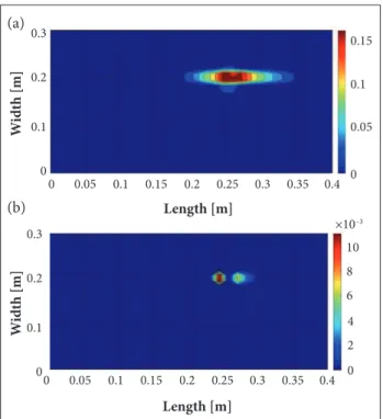
Figure 3a illustrates the damage scalar variable distribution along the plate’s external layer surface (Fig. 3b), for both external and internal layers of the laminated composite.
he diference between damages obtained on distinct layers can be clariied through the linear stress variation along the laminate thickness. Figure 3 illustrates that the maximum D value, in both external layers, is higher than it is in the central
Figure 3. Flat distribution of the variable D for both external (a) and internal (b) layers of the laminate.
hrough WT (DWT and CWT) and the DI (SAHTM, SAPS and DWTAC), the signal originated from the 10 irst vibration modes of the non-damaged laminated composite structure is analyzed. Regularization and interpolationtechniques are implemented to signals derived from the plate vibration modes for PI simulation. he signal interpolation is undertaken using cubic splines to increase the numerical data, and the Tikhonov regularization is then implemented to increase the perturbation generated by damage presences in CW graphs. hose foregoing techniques can be found in the study of Perreux et al. (1992). Ater being altered, the signal is then processed using the mother wavelets Daubechies (dbN), where N notiies the type of mother wavelet. he signal originated from the vibration mode is directly decomposed through WT, on the other hand, the DI require information from the non-damagedand damagedcondition.
In order to emphasize the inluence that choosing the most appropriate vibration mode may have on the damage location, Table 3 shows the DI values and the damage location through
(a)
J. Aerosp. Technol. Manag., São José dos Campos, Vol.9, No 4, pp.431-441, Oct.-Dec., 2017
438 Faria AW, Silva RA, Koroishi EH
the discrete mother wavelet db8 signal (DWT-db8), derived from the irst 10 vibration modes and adopting the damaged plate. From this table, it can be concluded that all DI reach their maximum values in the fourth vibration mode, the one capable of detecting the damage location, which was in turn veriied from the minimum percent error value in directions x and y of the plate (εx = 0.68%,εy = 4.50%), obtained between the point where the damage has been manifested (position of load application, x = 0.25 m and y = 0.20 m) and the one from the mother wavelet db8 (xmax = 0.2517 m, ymax = 0.2090 m); xmax and ymax are the points where the WC reach their maximum values over the surface of the analyzed plate. It can also be noted that the higher the DI values, the least the percent error (εx,εy).
he deriving vibration mode signal of the structure under a damaged condition has also been processed by CWT ater normalization and interpolation techniques had been applied using the mother wavelet Daubechies 8 (CWT-db8), as in the case of the previous simulation.
Figure 5 depicts the lat (Fig. 5a) and spatial (Fig. 5b) distribution of the WC via CWT-db8, which have been
Modes
Damage Indexes Peak coordinates (m)
DWTAC SAPS SAHTM xmax ymax
1 0.0182 7.8565e-4 0.0280 0.2262 0.1478
2 7.8565e-4 2.6202e-4 0.0162 0.2772 0.1507
3 2.8378e-4 2.5226e-4 0.0159 0.0030 0.1507
4 0.2556 0.7943 0.8912 0.2517 0.2090
5 0.0074 4.9348e-4 0.0222 0.1019 0.0866
6 3.9626e-4 2.9773e-4 0.0173 0.0030 0.1507
7 0.0014 1.7812e-5 0.0042 0.0030 0.2134
8 0.0339 0.0297 0.1723 0.0030 0.0881
9 0.0080 3.2681e-6 0.0018 0.0030 0.1567
10 0.0093 0.0198 0.1407 0.2517 0.1522
Table 3. DI values using the discrete mother wavelet db8 and as a function of its irst 10 vibration modes.
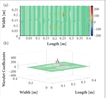
Figure 4 illustrates the DWT lat distribution along the plate surface (Fig. 4a) and space (Fig. 4b), obtained from the db8. he dynamic signals are gathered and processed via DWT-db8 considering only a damaged stage. It can be noticed from all igures that the area where the impulsive load was applied presents the higher WC amplitude.
It is observed from Figs. 4a and 4b that the DWT-db8 could capture the damage on the region around where the impulsive load was applied. In those igures, the DWC-db8 assume the highest value around the damaged area (central point: x = 25 m, y = 0.20 m) and the originated signal from the plate under a damaged stage is also capable of estimating the damage location (Fig. 4b).
fo = −116 N; Dmax= 0.1718; Damage position: xref= 0.25 m and yref = 0.20 m.
Figure 4. Wavelet coeficients of the DWT-db8 transform in a lat distribution along the plate surface (a) and spatially (b) distributed for computing the plate’s dynamic signal.
Figure 5. Wavelet coeficients for CWT-db8 according to a lat distribuition (a) and spatially distributed (b) along the plate’s surface.
200
0 100
–200
–200 0 200 400
–400
0.4
0.4
Length [m]
Length [m] Width [m]
W
id
th [m]
W
av
el
et C
o
effi
ci
en
ts
0.35 0.3
0.3 0.25
0.25 0.2
0.2
0.2 0.2
0.4
0 0 0.15 0.15
0.1 0.1
0.1 0.05
0.05
0 0
–100
200
0 100
–200
–200 0 200 400
–400
0.4
0.4
Length [m]
Length [m] Width [m]
W
id
th [m]
W
av
el
et C
o
effi
ci
en
ts
0.35 0.3
0.3 0.25
0.25 0.2
0.2
0.2 0.2
0.4
0 0 0.15 0.15
0.1 0.1
0.1 0.05
0.05
0 0
–100
(a)
(a) (b)
J. Aerosp. Technol. Manag., São José dos Campos, Vol.9, No 4, pp.431-441, Oct.-Dec., 2017
439
was in turn verified from the minimum percent error value in directions x and y of the plate (εx = 1.88%, εy = 5.20%), obtained between the point where the damage has been manifested (position of load application, x = 0.25 m and y = 0.20 m) and the one from the mother wavelet db8. It can also be noted that the higher the DI values, the least the percent error.
From Tables 3 and 4, it is observed that the damage index SAHTM manifests the higher order of magnitude when compared to DWTAC and SAPS, considering both DWT and CWT.
Since the fourth vibration mode is the most appropriate for locating the damage (Tables 3 and 4), the obtained values DWTAC, SAPS and SAHTM, according to the vibration modes (Tables 3 and 4), are normalized with reference to the DI values from the fourth vibration mode of DWT and CWT. From that, it is possible to generate the data presented in Table 5, where the damage index that best identifies the appropriate vibration mode for locating the damage considering both CWT and DWT is SAPS, since the normalized DI (compared to the damage index from the fourth vibration mode) generally assume the lowest values for SAPS in relation to other indexes. Furthermore, it can be noted that the damage index DWTAC exhibited the closest numerical results for the 2 transforms, as stated previously. Although SAHTM was able to identify the most appropriate vibration mode for locating the damage and determining its correct position, this damage index also presented considerable difficulties for accomplishing that task in comparison with SAPS and DWTAC. This fact is
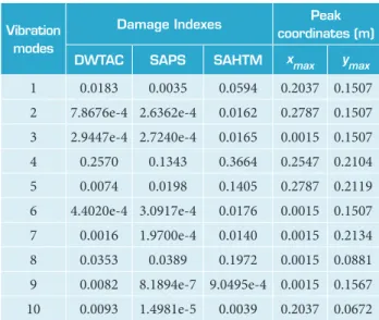
Vibration modes
Damage Indexes Peak coordinates (m)
DWTAC SAPS SAHTM xmax ymax
1 0.0183 0.0035 0.0594 0.2037 0.1507
2 7.8676e-4 2.6362e-4 0.0162 0.2787 0.1507
3 2.9447e-4 2.7240e-4 0.0165 0.0015 0.1507
4 0.2570 0.1343 0.3664 0.2547 0.2104
5 0.0074 0.0198 0.1405 0.2787 0.2119
6 4.4020e-4 3.0917e-4 0.0176 0.0015 0.1507
7 0.0016 1.9700e-4 0.0140 0.0015 0.2134
8 0.0353 0.0389 0.1972 0.0015 0.0881
9 0.0082 8.1894e-7 9.0495e-4 0.0015 0.1567
10 0.0093 1.4981e-5 0.0039 0.2037 0.0672
Table 4. DI values from the irst 10 irst vibration modes of the continuous mother wavelet db8 and a = 2.
fo = −116 N; Dmax= 0.1718; Damage position: xref= 0.25 m and yref = 0.20 m. directly applied to the fourth vibration mode of the plate under a damaged condition. he CWT translation coeicient (a) is equal to 2.
Just as in the preceding simulation involving CWT, DWT is also capable of determining the damaged area, assuming that the WC will reach high amplitudes in this location.
The relevance of selecting the appropriate vibration mode for detecting the damage can be verified from Table 4, where the DI values and damage location from the first 10 vibration modes of CWT-db8, adopting a scale parameter (a) equal to 2. From this table, it can be noticed that all DI reach their maximum values in the fourth vibration mode, the one capable of detecting the damage location, which
Mode DWT CWT
DWTAC SAPS SAHTM DWTAC SAPS SAHTM
1 0.071205 0.000989 0.031418 0.071206 0.026061 0.162118
2 0.003074 0.000330 0.018178 0.003061 0.001963 0.044214
3 0.001110 0.000318 0.017841 0.001146 0.002028 0.045033
4 1 . 0 0 0 0 0 0 1 . 0 0 0 0 0 0 1 . 0 0 0 0 0 0 1 . 0 0 0 0 0 0 1 . 0 0 0 0 0 0 1 . 0 0 0 0 0 0
5 0.028951 0.000621 0.024910 0.028794 0.147431 0.383461
6 0.001550 0.000375 0.019412 0.001713 0.002302 0.048035
7 0.005477 0.000022 0.004713 0.006226 0.001467 0.038210
8 0.132629 0.037391 0.193335 0.137354 0.289650 0.538210
9 0.031299 0.000004 0.002020 0.031907 0.000006 0.002470
10 0.036385 0.024928 0.157877 0.036187 0.000112 0.010644
J. Aerosp. Technol. Manag., São José dos Campos, Vol.9, No 4, pp.431-441, Oct.-Dec., 2017
440 Faria AW, Silva RA, Koroishi EH
confirmed by noticing the high normalized damage values compared to the ones obtained from SAPS and DWTAC.
According to Table 6, and in general terms, the wavelet transform DWT is the most appropriate for locating the damage, since its values of normalized DI have found to be, mostly, lower than the ones obtained from the wavelet CWT. However, this conclusion needs to be appraised carefully, since only 1 scale parameter (a = 2) was used to obtain the results presented in Table 4 (and consequently in Table 6) for the wavelet CWT.
Scale (a)
Damage Indexes Peak coordinates (m)
DWTAC SAPS SAHTM xmax ymax
2 0.2570 0.1343 0.3664 0.2547 0.2104
3 0.0023 1.2204e-4 0.0110 0.1438 0.0881
4 0.2740 0.4722 0.6872 0.2562 0.2104
5 0.0127 0.1560 0.3949 0.2562 0.2119
6 0.2169 0.2276 0.4771 0.2577 0.2104
7 0.1159 0.1918 0.4380 0.2577 0.2104
8 0.1871 0.2237 0.4730 0.2607 0.2104
9 0.2280 0.2983 0.5462 0.2607 0.2104
10 0.4384 0.2648 0.5146 0.2622 0.2090
Table 6. DI values according to different scale parameters using CWT-db8 applied to the fourth vibration mode.
fo = −116 N; Dmax= 0.1718; Damage position: xref = 0.25 m and yref = 0.20 m.
Table 6 presents the damage location values obtained from CWT-db8, employing diferent scale parameters that vary from 2 to 10 and adopting the signal from the fourth vibration mode. From this table, it can be inferred the 3 DI reach relatively narrow values according to scale 3, which is not able to detect the damage location. Hence, DI may be used as a guidance of the most appropriate CWT scale parameters (a) for damage detection in damaged laminated composite structures.
CONCLUSION
In SHM applications, the DWT-1-D and CWT-1-D are adopted for spatially decomposing the vibration modes of damaged composite structures, even though in a 1-D space. he
WC obtained from this decomposition reach maximum values around the damaged area, which provides the approximate damage location.
It has been observed that the fundamental vibration mode (the very first one) is not necessarily the best for detecting the damage in laminated composite plates, since the high frequency modes are equally efficient considering the same goal. Thus, the analyzedDI(SAHTM, SAPS and DWTA) are crucial mathematical tools for pointing out the most desirable vibration mode for damage detection.
It is worth noting that the signal is analyzed by DWT and CWT considering the structure under a damaged stage only, while theDIrequire signal information from both stages, damaged and non-damaged. It has been verified that the vibration mode pattern may accentuate the existent singularities in the wavelet coeicients.
Both DWT and CWT are capable of detecting the matrix damage location in damaged laminated composite structures, yet the continuous transforms demand that the scale parameters (a) must be established and, due to this fact, they present a relatively higher computational cost than discrete transforms. The DI presented herein may be used as a guidance on defining the mentioned scalar parameters. Hence, considering the 2 wavelet transforms, the discrete transform DWT, when associated to either DWTAC or SAPS, would be the most appropriate for the online identification of the matrix damage mechanism proposed and implemented herein.
AUTHOR’S CONTRIBUTION
Conceptualization, Methodology, and Investigation, Faria AW; Writing – Original Drat, Faria AW and Silva RA; Writing – Review & Editing, Faria AW, Silva RA, and Koroishi EH; Funding Acquisition, Resources, and Supervision, Faria AW.
ACKNOWLEDGEMENTS
J. Aerosp. Technol. Manag., São José dos Campos, Vol.9, No 4, pp.431-441, Oct.-Dec., 2017
441
REFERENCES
Bathe KJ (1996) Finite element procedures in engineering analysis. New Jersey: Prentice-Hall.
Boubakar ML, Trivaudey F, Perreux D, Vang L (2002) A meso-macro inite element modeling of laminate structures, Part 1: time-independent behavior. Compos Struct 58(2):271-286. doi: 10.1016/ S0263-8223(02)00049-1
Chang CC, Chen LW (2004) Damage detection of a rectangular plate by spatial wavelet based approach. Appl Acoust 65(8):819-832. doi: 10.1016/S0003-682X(04)00033-7
Faria AW (2010) Modélisation par éléments inis de plaques composites: contribuition a l’etude de l’amortissement, endommagement et prise en compte d’incertitudes (PhD thesis). Uberlândia: Universidade Federal de Uberlândia. In Portuguese.
Hernández E, Weiss G (1996) A irst course on wavelets. Boca Raton: CRC Press.
Katunin A (2011) Damage identiication in composite plates using two-dimensional B-spline wavelets. Mech Syst Signal Process 25(8):3153-3167. doi: 10.1016/j.ymssp.2011.05.015
Loendersloot R, Moix-Bonet M (2015) Damage identiication in composite panels using guided waves. Proceedings of the 5th CEAS Air & Space Conference; Amsterdam, The Netherlands.
Loutridis S, Douka E, Hadjileontiadis LJ, Trochidis A (2005) A two-dimensional wavelet transform for detection of cracks in plates. Eng Struct 27(9):1327-1338. doi: 10.1016/j.engstruct.2005.03.006
Mahmoudi S, Trivaudey F, Bouhaddi N (2015) Nonlinear dynamic response analysis of damaged laminated composite structures. In: Chouchane M, Fakhfakh T, Daly H, Aifaoui N, Chaari F, editors. Design and modeling of mechanical systems - II. Proceedings of the Sixth
Conference on Design and Modeling of Mechanical Systems, Cmsm 2015. Berlin: Springer-Verlag. p. 545-552.
Oppenheim AV, Schafer RW (1975) Digital signal processing. New Jersey: Prentice-Hall.
Perreux D, Suri D, Varchon D, Oytana C (1992) Endommagement mécanique de matériaux composites: rôle sur les propriétés hygrothermiques. Proceedings of La Construction Navale en Composites; Paris, France.
Rah K (2007) Damage modeling in laminated composite structures. Proceedings of the FirW PhD Symposium; Gent, Belgium.
Reddy JN (1997) Mechanics of laminated composite plates: theory and analysis. 2nd edition. Boca Raton: CRC Press.
Reddy JN, Miravete A (1995) Practical analysis of composite laminates. Boca Raton: CRC Press.
Rucka M, Wilde K (2006) Application of continuous wavelet transform in vibration based damage detection method for beams and plates. J Sound Vib 297(3-5):536-550. doi: 10.1016/j.jsv.2006.04.015
Stark HG (2005) Wavelets and signal processing: an application-based introduction. Berlin; Heidelberg; New York: Springer.
Wang Q, Deng X (1999) Damage detection with spatial wavelets. Int J Solid Struct 36(23):3443-3468. doi: 10.1016/S0020-7683(98)00152-8