INTRODUCTION
An important difference between natural teeth and dental implants is the fact that dental im-plants do not move in response to applied loads. As titanium implants do not have a periodontal ligament, intensive loads are transmitted and dis-tributed to the adjacent bone. However, it is de-sirable in the implant-supported prosthesis that masticatory loads are distributed evenly.
There is a physiological limit of bone toler-ance to tensile and compressive strengths and
Photoelastic analysis of stress distribution on parallel and angled
implants after installation of fixed prostheses
Análise fotoelástica de distribuição de tensões em implantes
paralelos e angulados após a instalação de próteses fixas
Cristiane Ueda*
Roberto Adrian Markarian* Cláudio Luiz Sendyk** Dalva Cruz Laganá**
bone-resorption may occur. The loading thresh-old tolerated by the bone is not well-known and the failure of osseointegration can be caused by bone resorption as a result of unfavorable stress concentrations11. In accordance to Kohn16 (1992),
tension distribution is one of the important factors related to implant success; the tensions should be transferred to the adjacent bone, preferentially in an orientation and magnitude that keep the tissues viability near a physiologic state.
* Graduate Students; **Assistant Professors – Department of Prosthodontics, School of Dentistry, University of São Paulo.
ABSTRACT: The longevity of implant-supported prosthetic rehabilitation depends largely on how the masticatory
forces are transferred to the implants and surrounding bone. Anatomical conditions, bone morphology and aes-thetics usually dictate implant placement in less than ideal positions for prosthetic rehabilitation and sometimes it is possible to find them with different inclinations. The purpose of this paper was to compare, through photoelastic analysis, the stress distribution in a fixed prosthesis with 3 parallel implants, to the stress distribution in the same prosthesis in the existence of an angled central implant. Two photoelastic resin models were made and a polari-scope was used in the visualization of isochromatic fringes formed in the models when axial loads of 2 kg, 5 kg and 10 kg were applied to a unique central point of the prosthesis. The presence of inducted tensions (preloads) was observed in the models after applying torque to the retention screws. Preloads were intensified with the incidence of occlusal forces. In the parallel implants, the force dissipation followed the long axis. The angled implant had a smaller quantity of fringes and the stresses were located mostly around the apical region of the lateral implants.
DESCRIPTORS: Dental implantation, endosseous; Prosthesis implantation.
RESUMO: A longevidade das reabilitações orais implanto-suportadas depende, em grande parte, de como as forças
mastigatórias são transferidas aos implantes e ao osso que os circunda. Condições anatômicas, morfologia óssea e estética muitas vezes ditam a colocação de implantes em posições que não são ideais para a reabilitação protética, e podemos encontrá-los com diferentes inclinações. A proposta deste trabalho foi comparar, através de análise fotoelástica, a dissipação de tensões em uma prótese fixa com 3 implantes paralelos entre si com a dissipação de tensões na mesma prótese na existência do implante central angulado. Foram confeccionados dois modelos de resina fotoelástica. Utilizou-se um polariscópio para visualização das franjas isocromáticas que se formaram nos modelos fotoelásticos quando cargas axiais de 2 kg, 5 kg e 10 kg foram aplicadas em um mesmo ponto central da prótese. Verificou-se a indução de tensões (pré-tensões) nos modelos após o apertamento dos parafusos de reten-ção das próteses. As pré-tensões foram agravadas com a incidência de forças oclusais. Nos implantes paralelos, a dissipação de forças seguiu os longos eixos. No implante angulado houve menor quantidade de franjas, e as ten-sões estavam localizadas principalmente ao redor da região apical dos implantes laterais.
According to Canay et al.5 (1996), there is little
information about the magnitude of stress thresh-old to initiate bone resorption. A great number of local and systemic factors influence bone behav-ior and some researchers accept the concept that loading represents the main factor for regulation of bone remodelling during life.
Photoelastic stress analysis is based on the property that some transparent materials exhibit colorful patterns when submitted to loads and viewed with polarized light. This array of colored patterns is called isochromatic fringes. Studies with photoelastic analysis have been throughly conducted to determine the stress distribution around natural teeth, abutments of removable par-tial prosthesis and fixed parpar-tial prosthesis8; around
endosseous implants under complete dentures9,14
or to determine stresses around endosseous im-plants supporting fixed prosthesis1,6,8,12,13,15,17.
The stress distribution around implants placed in the first molar mandibular area was biomechan-ically analyzed in a two-dimensional mathematical model according to the work of Canay et al.5 (1996).
Vertical and angled implants were submitted to vertical loads of 100 N and lateral loads of 50 N. The stress-inducted difference in the surrounding bone, in vertical and angled implants, was higher around the cervical region and lower around the middle third and apical regions. The long-term success of dental implants seems to be critically related to bone presence in the cervical region of dental implants.
Federick, Caputo9 (1996) used photoelastic
models to verify the loads transferred from over-dentures to implants with: Hader splinting bar, Hader splinting bar with distal resilient cap ERA®
system, and only with the ERA® resilient cap
sys-tem, with 2 vertical implants parallel to each other and with 2 convergent inclined implants for oc-clusion with 17º of inclination. The ERA® system
generated tensions with smaller intensity and more uniform distribution. They concluded that regard-less of the overdenture retention system used, the higher stress concentration was found in the distal surfaces of the inclined implants. Brosh et al.3
(1998) also verified that vertical loads applied in angled abutments produced higher stresses at the coronal zone of the implant compared with straight abutments.
Guichet et al.12 (2000) compared
cement-re-tained or screw-recement-re-tained implant restorations, us-ing a photoelastic model with three implants. The marginal gaps were measured with a microscope
before and after the cementation or screwing of the prosthesis. The photoelastic analysis revealed that the cement-retained prosthesis had a more equal stress ditribution than its screw-retained counterparts.
The previous planning of implant localization interferes in the stress distribution and because of some differences observed the use of parallel implants rather than angled ones is preferable. The longevity of the treatment can be increased if load distribution on bone is better understood2,4,7.
Thus, every effort should be made to achieve an ideal implant location and occlusion should be me-ticulously determined to avoid eccentric loading.
The aim of the present study was to compare, through photoelastic analysis, the distribution of stress of a fixed prosthesis with 3 parallel implants to the distribution of stress in the same prosthe-sis with an angled central implant, under vertical loading.
MATERIAL AND METHODS
Two photoelastic resin blocks were made in the following dimensions: 30 mm in height, 75 mm in width and 12 mm in thickness. In order to obtain the models in resin, a preliminary plaster model was made using 3 drillings to place 3 implants in the corresponding positions of the first premolar, second premolar and first molar. All of them were placed parallel to each other with a distance of 4 mm between implants (model P). In the second model (A) the implant corresponding to the infe-rior second pre-molar had its mesiodistal angle changed to 30º.
Three implant analogs were positioned in the drillings. Upon these analogs the impressioned copings were positioned. This impression was the photoelastic resin modeling pattern. Three Conexão® implants, (Conexão Master, São Paulo,
Brazil) 10.0 mm in length and 3.75 mm in diam-eter, were fixed in their impression copings, in the silicon molding. The PL-2 Liquid Plastic resin (Measurement Group Inc., Raleigh, USA) was poured in order to obtain the photoelastic model with the implants transferred. The complete os-seointegration is supposed to allow a contact of the polymerized resin and the implants.
A metallic structure was manufactured using prefabricated cylindrical titanium tubes, Conexão®
through a Laboval 4 microscope (Carl Zeiss, Jena, Switzerland) with a 170 X lens. A torque control (Lifecore Biomedical Inc., California, USA) was used in the attachment of the prosthesis to the implants, with a calibrated force of 20 N, according to manufacturer’s specifications.
The prosthesis was subjected to loads of 2 kg, 5 kg, and 10 kg through a tip connected to the central point of the prosthesis. The model was im-mersed in mineral oil to decrease the light refrac-tion of the surface and to facilitate the observarefrac-tion of the isochromatic fringes, according to Federick, Caputo9(1996).
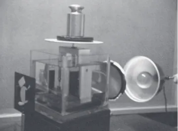
High-resolution digital photos were taken with a Mavica FD 97 camera (Sony, California, USA). The stresses generated in photoelastic models for each loading application were observed. The analysis was made using a circular polariscope, specially manufactured for this study, an analyser, and a source of white light to produce internal colored pattern stresses in the photoelastic mate-rial (Figure 1).
After the photographic recordings of model P, the same prosthesis was installed in model A. The visual interpretation of the isochromatic fringes of the photoelastic model was performed by two ex-aminers and to help qualitative analysis, the area around each implant was divided into three points: left cervical, apical, and right cervical, identified by the letters of the alphabet (Figure 2).
Each fringe represented a stress level and for analysis, two factors were considered, according to French et al.10 (1989):
1. The larger the number of fringes, the higher the stress magnitude.
2. The closer the fringes were to each other, the higher the stress concentration.
RESULTS
Observing the photographic records of the models without load application, we did not ob-serve fringes in the photoelastic resin model, which
FIGURE 1 - Polariscope.
A
B E H
P
C D F G I A
B E H
A
C D F G I
FIGURES 5 AND 6 - Photographic recordings of models P (5) and A (6), after the installation of the prosthesis (torque
of 20 N).
FIGURES 7 AND 8 - Photographic recordings of models P (7) and A (8), after the load application (2 kg).
FIGURES 3 AND 4 - Photographic recordings of models P (3) and A (4), before the installation of the prosthesis and
the load application.
3 4
5 6
indicates the absence of tension14 (Figures 3 and
4).
The first analyzed condition was the torque of the screws during the installation of the prosthe-sis, when a small stress was observed, in both the parallel and angled implants (Figures 5 and 6).
The load application in the parallel implants showed lower stress intensity, better distribution and uniformity among them, with a larger concen-tration in the apical region, mostly in the central implant. In the angled implant, the intensity of the stress was higher and the location of this stress in the central implant was smaller. The concentra-tion was higher in the implants located on both extremities. In the two models, a higher intensity of the stress was observed when a greater load was applied (Figures 7 to 12).
Upon the application of 5 kg of load, the stress increased in the two models (Figures 9 and 10). We can note that in the three parallel implant model, the tensions were concentrated on the middle im-plant just in the central location of the load appli-cation. In the model with the angled implant, this one maintained a lower stress concentration when compared to the other two lateral parallels.
The apical region of the implants had a high-er stress concentration when 10 kg of load was applied (Figures 11 and 12), following the same concentration standard of lower loads. In model P, with the parallel implants, the concentration of stress was higher in the central implant and in model A, the stress concentration was higher in the lateral implants.
For quantitative analysis of the stress distri-FIGURES 9 AND 10 - Photographic recordings of models P (9) and A (10), after the load application (5 kg).
FIGURES 11 AND 12 - Photographic recordings of models P (11) and A (12), after the load application (10 kg).
9 10
bution a sequential table was used following color sequences of fringes (Table 1).
The values of the isochromatic fringes ex-pressed through the respective numbers of order were harvested in points selected from models P and A (Figure 2). The results of readings were ex-pressed in Table 1 and Graphs 1 and 2.
DISCUSSION
According to the research by Deines et al.8
(1993) and French et al.10 (1989), factors such as
concentration and magnitude of stress are related to variables such as the antagonistic tooth, oc-clusal force, number of implants to distribute the load, position of the implant, rigidity of the pros-thesis and geometry of the implant distribution. These results are in accordance to the work pre-sented by Kenney, Richards14 (1998) that had the
same lengths, the same widths and equal formats in their angulations, thus validating the compari-sons studied. These principles were applied in our study.
In this model the force applied on the pros-thesis was axial. However, it is known that in an
in vivo situation, transversal and lateral forces are
also present. We used only axial loads because of our agreement with the works of Deines et al.8
(1993) and Canay et al.5 (1996) that considered
these forces more relevant in clinical conditions. Photoelastic analysis has been widely used in dentistry to study the biomechanical stress trans-fer in several kinds of prosthesis. The photoelastic model is a different homogeneous plastic material that simulates human bone constituted of corti-cal bone and cancellous bone. We realized that the magnitude of the stresses in real bone can be different from those in a model. However, the lo-cation and general standard of these stresses are similar15. The technique used also facilitates a
two-dimensional view of the stress concentration14.
Waskewicz et al.17 (1994) affirmed that stress
generation is initiated with the fixation of the pros-thesis to the abutments and according to them this force can decrease with a well-settled structure. This study recommends the section of the pros-thesis for soldering. Our work also verified a low stress generation when turning the screws of the prosthesis. Considering that the prosthesis was passively settled, such tensions were not consid-ered very significant. Guichet et al.12 (2000) studied
the difference between cement-retained and screw-retained implanted prosthesis and concluded that the significant decrease in the marginal fit was
obtained with the screw-retained prosthesis that was associated with higher stress generation. On the other hand, an increase of the marginal fit of the cement-retained prosthesis was associated to lower stress generation in the photoelastic resin model. We believe that this occurred because part of the occlusal loads are dissipated by the cement layer, suggesting that the cementation layer can be broken with consequent detachment of the pros-thesis.
According to Canay et al.5 (1996) and Brosh et
al.3 (1998) the angled implants generated excessive
tensions in the cervical region when submitted to vertical loads. This fact has an importance in the longevity of the implants since bone loss in the cervical region can compromise the stability of the implant, promoting the penetration of pathogenic bacteria, causing inflammation, bone loss and mobility of the implant. The researchers affirm that the angulated implants, usually planned in the posterior region where vertical loads are com-mon, should be avoided. Federick, Caputo9 (1996)
agree that a perpendicular placement of implants TABLE 1 - Fringe order.
Color Fringe order
Black 0.00
Gray 0.28
White 0.45
Pale yellow 0.60
Orange 0.80
Dull red 0.90
Purple (tin of passage) 1.00
Deep blue 1.08
Blue-green 1.22
Green-yellow 1.39
Orange 1.63
Rose-red 1.82
Purple (tin of passage) 2.00
Green 2.35
Green-yellow 2.50
Red 2.65
Red/green transition 3.00
Green 3.10
Pink 3.65
Pink/green transition 4.00
to the occlusal surface can reduce the intensity of the tensions and the stress concentration around them.
Our study found a smaller tension concen-tration in the angled implant, unlike the results found in other studies3,6,9. This can be explained
by the fact that in our work we evaluated three implants and a fixed prosthesis and not only one or two implants.
In our research, the angled implant was posi-tioned between two other parallel implants which could be considered interesting in rehabilitation
planning where parallel implant placement is not possible. This is also interesting considering that we did not find a higher concentration of stress in the cervical region of the angled implant.
CONCLUSIONS
Considering some limitations of our study we were able to conclude that:
• An induction of preloads in models P and A was observed after turning the retention screws of the prosthesis. These preloads were magnified after occlusal forces were applied. In
0 0. 6 0. 9 0. 9
0 0 0 0 0 0 0 0
1 0. 28 1 1. 39 0. 8 0 1 0 0.5 1 1.5 F rin ge o rd er
A B C D E F G H I
Analyzed points
20 N 2 kg 5 kg 10 kg
0. 6 0. 6 0. 6 0. 6 0. 6 0. 6 0. 6 0. 6 0. 6 0. 6 0. 9 0. 9 0. 9 0. 9 0. 9 0. 9 0. 9 0 0. 6 0. 9 0. 9
0 0 0 0 0 0 0 0
1 0. 28 1 1. 39 0. 8 0 1 0 0.5 1 1.5 F rin ge o rd er
A B C D E F G H I
Analyzed points
20 N 2 kg 5 kg 10 kg
0. 6 0. 6 0. 6 0. 6 0. 6 0. 6 0. 6 0. 6 0. 6 0. 6 0. 9 0. 9 0. 9 0. 9 0. 9 0. 9 0. 9
the parallel implants, the stress distribution followed the long axis, and the fringes con-centration was smaller. The angled implant had fringes in a smaller quantity, located in a mostly dispersed manner around the apical region of both lateral implants.
• Although the photoelasticity results illustrated characteristics with regard to overall location and concentration of stresses, more
quanti-tative data could be obtained by using strain gauges or finite element analysis.
ACKNOWLEDGMENTS
FAPESP (The State of São Paulo Research Foundation), for research funding conceded in 2001 and 2002 (process 00/12921-3); Conexão Systems, for the supply of the implants and components; Titanium Central Laboratory, for technical works.
REFERENCES
1. Assif D, Marchak B, Horowitz A. Analysis of load transfer and stress distribution by an implant-supported fixed partial denture. J Prosthet Dent 1996;75:285-91. 2. Bidez MW, Misch CE. Force transfer in implant
den-tistry: basic concepts and principles. J Oral Implantol 1992;18:264-74.
3. Brosh T, Pilo R, Sudai D. The influence of abutment an-gulation on strains and stresses along the implant/bone interface: comparison between two experimental tech-niques. J Prosthet Dent 1998;79:328-34.
4. Bruggenkate CM, Sutter F, Oosterbeek HS, Schroed-er A. Indications for angled implants. J Prosthet Dent 1992;67:85-93.
5. Canay S, Hersek N, Akpinar I, Asik Z. Comparison of stress distribution around vertical and angled implants with fi-nite-element analysis. Quintessence Int 1996;27:591-8. 6. Clelland NL, Gilat A, McGlumphy EA, Brantley WA. A pho-toelastic and strain gauge analysis of angled abutments for an implant system. Int J Oral Maxillofac Implants 1993;8:541-8.
7. Coward TJ, Watson RM. Locating angulated abutments: a technical note. Int J Oral Maxillofac Implants 1997;12:82-3.
8. Deines DN, Eick JD, Cobb CM, Bowles CQ, Johnson CM. Photoelastic stress analysis of natural teeth and three osseointegrated implant designs. Int J Periodontics Re-storative Dent 1993;13:541-9.
9. Federick DR, Caputo AA. Effects of overdenture reten-tion designs and implant orientareten-tions on load transfer characteristics. J Prosthet Dent 1996;76:624-32.
10. French AA, Bowles CQ, Parham PL, Eick JD, Cobb CM. Comparison of peri-implant stresses transmitted by four commercially available osseointegrated implants. Int J Periodontics Restorative Dent 1989;9:221-30.
11. Glantz PO, Rangert B, Svensson A, Stafforce GD, Arnvidarson B, Randow K, et al. On clinical loading of osseointegrated implants. A methodological and clinical study. Clin Oral Implant Res 1993;4:99-105.
12. Guichet DL, Caputo AA, Sorensen JA. Passivity of fit and marginal opening in screw- or cement-retained implant fixed partial denture designs. Int J Oral Maxillofac Im-plants 2000;15:239-46.
13. Inan O, Kesim B. Evaluation of the effects of restora-tive materials used for occlusal surfaces of implant-sup-ported prostheses on force distribution. Implant Dent 1999;8:311-6.
14. Kenney R, Richards MW. Photoelastic stress patterns produced by implant-retained overdentures. J Prosthet Dent 1998;80:559-64.
15. Kim WD, Jacobson Z, Nathanson D. In vitro stress analysis of dental implants supporting screw-retained and cement-retained prostheses. Implant Dent 1999;8:141-51.
16. Kohn DH. Overview of factors important in implant design. J Oral Implantol 1992;18:204-19.
17. Waskewicz GA, Ostrowski JS, Parks VJ. Photoelastic analysis of stress distribution transmitted from a fixed prosthesis attached to osseointegrated implants. Int J Oral Maxillofac Implants 1994;9:405-11.