INFLUENCE OF HYDRODYNAMIC CONDITIONS AND NOZZLE
GEOMETRY ON APPEARANCE OF HIGH SUBMERGED
CAVITATING JETS
by
Ezddin HUTLIa*, Salem ABOUALIa, Mohamed BEN HUCINEa, Mohamed MANSOURa, Milo{ S. NEDELJKOVI]a, and Vojislav ILI]b
aFaculty of Mechanical Engineering, University of Belgrade, Belgrade, Serbia bSchool of Engineering, University of Western Sydney, Western Sydney, Australia
Original scientific paper DOI: 10.2298/TSCI120925045H
Based on visualization results of highly-submerged cavitating water jet obtained with digital camera, the influences of related parameters such as: injection pres-sure, nozzle diameter and geometry, nozzle mounting (for convergent/divergent flow), cavitation number and exit jet velocity, were investigated. In addition, the in-fluence of visualization system position was also studied. All the parameters have been found to be of strong influence on the jet appearance and performance. Both hydro-dynamical and geometrical parameters are playing the main role in behav-ior and intensity of cavitation phenomenon produced by cavitating jet generator. Based on our considerable previous experience in working with cavitating jet gen-erator, the working conditions were chosen in order to obtain measurable phenom-enon.
Key words: nozzle, convergent, divergent, jet, cavitation cloud, shear stress, vortex ring, length, angle
Introduction
Flow visualization has been an important tool in fluid dynamics research; it has been used extensively in engineering, physics, medical science, meteorology, oceanography, aerody-namics,etc. As was determined from the published literature, not much is known about the un-steady behaviour of the cavitating jet and the development, as well as the collapse of the cavita-tion clouds on the impinging surface [1, 2]. Cavitacavita-tion causes many adverse effects that are to be avoided or at least controlled in any hydraulic facility. On the other hand, cavitation is used in many diverse scientific and industrial applications (jet cutting, under water cleaning,etc.)via
cavitation clouds produced by cavitating jets. As is well known, the impingement of cavitating jet leads to serious erosion in valves and hydraulic equipment. In order to reduce cavitation ero-sion in valves and oil hydraulic equipments or to improve the performance of jet cutting or under water cleaning, it is necessary to have an adequate knowledge about the mechanism and behav-iour of cavitation phenomenon that appears as a cavitating jet [3]. The great advantage of testing cavitation phenomenon by the use of cavitating jet is that the cavitating jet apparatus can simu-late different cavitating conditions. If a relation between the cavitation intensity in a cavitating jet and the related parameters would be investigated precisely, the key parameter to predict the cavitation behaviour could be clarified [4]. The flow across the holes of a nozzle can be con-trolled by different factors, which may be classified under three categories: operation
tions, orifice geometry, and flow properties. The importance of these parameters may be under-stood from the results presented by many authors who have investigated the performance of cavitating jets [5-8]. If the unsteady behaviour and the jet structure are clarified in detail, it is ex-pected that the jet working capacity could be drastically improved [1, 2]. The collapses of the cavities are the origin of high pressure spikes on the specimen. The amplitude of the collapse stress pulses is variable and random, but it can reach up to 1500 MPa, which is a level of stress high enough to deform or to rupture the surface of most industrial alloys [9]. In addition, the col-lapse of cavitation bubbles produces not only mechanical impact, which normally results in cav-itation erosion in fluid machinery, but also high temperature spots which have a significant ther-mal effect. The understanding of these mechanical and therther-mal effects and their application may be employed to improve the corrosion resistance of a material [10]. As reported in previous work the cavitation clouds in cavitating jet has so fast dynamic behaviour in order of fewms which needs special techniques in order to couch the behaviour in time and space [11-14].
The aim of this study is to examine the influences of hydrodynamic conditions, such as cavitation number, exit jet velocity, and the nozzle configuration (convergent or divergent) on cavitation phenomenon, thus analyzing the performance of the jet. The flow visualization is used here to achieve these goals. In this paper, A NIKON COOLPIX 990 digital camera was used for visualization and investigation of the influences of hydrodynamic conditions, nozzle geometry, and the visualization system arrangements. The nozzles used were mounted to be ei-ther convergent or divergent. The visualization investigations were done using a stroboscope to illuminate the cavitating jet for 30ms. The flash frequency was 50 Hz while the shutter camera frequency was 1/30 and 1/60 s–1. The jet images were taken as a movie at approximately 600 frames in 40 s (15 frames per second). The jet behaviour has then been followed by extracting the appropriate images from the recorded movies. In this work the investigation was on the cavi-tation behaviour only in space and in order to overcome the time effect (visualization system) many single shoots has been done for the same working conditions and the average was used for further analysis process.
Experimental set-up, measurements, and error analysis
Shear stress and the cavitation vortex ring in the cavitating jet
When the jet penetrates the stagnant water in the test chamber, a shearing force is gen-erated between the jet and the stagnant water (the shearing force is dependent on the velocity gradient), resulting in the generation of a vortex. The existence of a vortex can be tested by many parameters such as the circulation (G), the vorticity (w), the centrifugal force (FC) and the energy of the vortex. The change from a constant vorticity to a radially varying vorticity is much sharper for a turbulent vortex ring. In a turbulent field, the presence of additional vortices with random circulations in the neighbourhood will disturb the closed streamline pattern around any vortex. In the case of cavitating jets (two phase flow) (pulsed jet: injection of fluid with certain frequency), a part of the exchange momentum is established by a change of the phase (density change), and also, because the Prandtl mixing length theory is based on the assumption that a fluid parcel has to travel over a length (lm) before its momentum is transferred. Basically, for sin-gle phase flow it is easy to understand the concept of the mixing length: since turbulent stress is caused by momentum transfer process, it is useful to have a physical length that defines when the momentum has been transferred [15], while in the case of two phase highly turbulent flow, as in a cavitating jet, it is complicated. Maybe, it can be assumed that the mixing length is equal to the width of the jet at a given point. In cavitating jets created by a circular nozzle, the initial vor-tex of the jet should produce a nearly axisymmetric low pressure. This low pressure lead to the formation of ring-like cavitation bubbles in the near field of the jet. In the early stages of jet de-velopment, cavitation bubbles are mostly generated inside and neighbouring the starting vorti-ces and are sometime connected with each other in the form of a ring. The bubble rings travel downstream with the initial vortices and often survive for a certain distance [2, 11]. In the later stages of jet development, isolated bubbles are formed behind the initial vortices; some are in groups and others are randomly distributed in the jet shear layer. In the case of high continuously submerged cavitating jets as in our case, it is so complicated task to describe the stages of the mechanism of vortex creation, since there is two phase flow in addition to the rebounding and collapsing of the cavitation bubbles, which frequently occur along the jet trajectory producing very fast micro and nano liquid jets and shock waves. These liquid jets produce many new vor-texes; in fact, thereby turbulent flow and chain vortex production exist even it will be in the level of micro size [2, 11, 15].
Influence of nozzle conicity
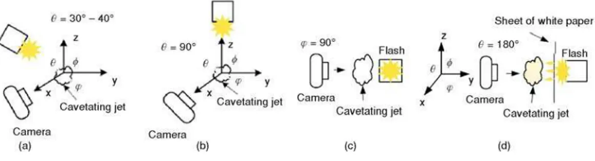
Investigation of the influence of nozzle conicity was done by mounting the nozzle in two ways, once to have a nozzle divergent and once to have it convergent. The installation of the visualization system is shown in fig. 1(b). The investigation was done for four groups of
ing conditions for each configuration only two groups are presented for each configuration (di-vergent and con(di-vergent). The cavitation number was calculated ass = (pref. –pv/0.5 ruref.2 ). wherepv(T) is the saturation (vapor) pressure,r– the fluid density,pref.– the reference pressure (p2),uref.– the reference speed (VJ). The given exit velocities (VJ) during cavitation are based on the single phase flow. For the same mass flow rate, the actual flow velocity will be higher than given.
Analysis for the divergent conical nozzle
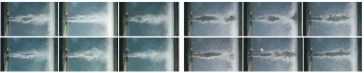
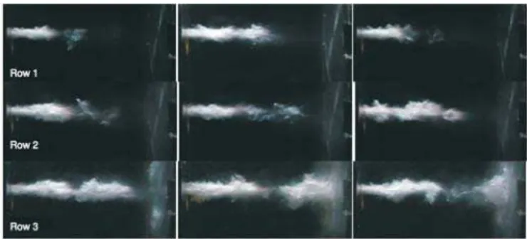
The analysis of the obtained movies under the conditions presented in table1 has been done. Some images are given here to help in the explanation, In fig. 2 only two images presented because there is no difference in the contents of the obtained images extracted from the related recorded movie atP1= 8 bar (tab. 1), the images fig. 2 show that the jet is comprised only of very tiny individual bubbles (no clouds), the spreading angle of the jet is wider than in the other im-age for the other conditions. The existence of tiny bubbles is attributed to the inception of cavita-tion inside the nozzle (not at the nozzle outlet). The result of analysis of movies shows that the behavior is dependent on working conditions examples, Images in fig. 3 (first row,P1= 45 bar) show that the incipience of cavitation began from the nozzle exit as dense clouds and then im-mediately transformed to lighter clouds, which appear as smoky clouds after about 20% of the distance between the nozzle exit and the target surface (which is designated byx,x= 25.67 mm) (first 3 images). The analyses of the remaining groups of images in fig. 3 (first row,P1= 195 bar) show that, the jet penetration, jet breaking point position, jet-spreading angle, and jet density (individual bubbles and bubble clusters) are in-creased as upstream pressure (P1) increases. At the end of the jet trajectory, when the jet strikes the target wall at highP1, it spreads radially and covers all the area with tiny bubbles. These bubbles collapse at different radial positions on the target surface or near it. The position of bub-ble collapse depends on the radial pressure
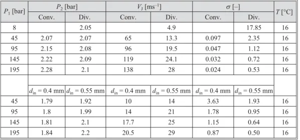
dis-Table 1. Working conditions for investigation of influence nozzle conicity and dimensions
P1[bar]
P2[bar] VJ[ms–1] s[–]
T[°C] Conv. Div. Conv. Div. Conv. Div.
8 2.05 4.9 17.85 16
45 2.07 2.07 65 13.3 0.097 2.35 16
95 2.15 2.08 96 19.5 0.047 1.12 16
145 2.22 2.09 119 24.1 0.032 0.72 16
195 2.28 2.1 138 28 0.024 0.53 16
din= 0.4 mmdin= 0.55 mm din= 0.4 mm din= 0.55 mm din= 0.4 mm din= 0.55 mm
45 1.79 1.92 10 14 3.63 1.93 16
95 1.8 1.99 14 21 1.78 0.95 16
145 1.81 2.1 17.7 25 1.15 0.64 16
195 1.84 2.2 20.5 29 0.87 0.50 16
Figure 2. Appearance of the cavitating jet divergent nozzle (P
tribution while the local stress produced as a result is a function of two parameters: the bubble density and the bubble size [8].
Analysis for the convergent nozzle
Figure 3 (second row,P1= 45 and195 bar), for convergent nozzle (din= 1 mm anddout= = 0.45 mm), reveals that the jet behavior with up-stream pressure is the same as in the case of di-vergent nozzle. However, the position of the breaking point, jet penetration, spreading angle, and the jet density in the case of nozzle convergence are much greater than for the divergent case. This is attributed to the big difference in the velocities for the two nozzle directions. In the case of convergent nozzle atP1= 8 bar, no cavitation was observed. However, atP1= 25 bar the phenom-enon appeared at nozzle exit with irregular and rare frequency: it was unstable, and this can be as-sumed as the inception of cavitation (no image was obtained for this case). In the groups of im-ages in fig. 3 (last three imim-ages in second row,P1= 195 bar) many bubbles distributed throughout the whole area may be observed, this has also been seen withP1= 145 (not presented because of space). This feature is related to the intensive vortex action in the jet, which leads to the liberation of bubble growth and their spreading and floating in the chamber (gas bubble). Finally, these bubbles collapse when they meet the point of sufficient pressure in their path. However, these gas bubbles have longer lifetime as compared to cavitation (vapor) bubbles [2, 11].
The influence of nozzle dimensions on the cavitating jet behaviour
Visualizations of jets created by two different nozzles (both are divergent nozzles but of different dimensions) were also done for working conditions in tab. 1. Only two for each noz-zle are presented (atP1= 95 and 195 bar), fig. 4 presents images are extracted from obtained the results (recorded movies). Upstream pressure (P1) was kept constant, as well as working fluid temperature (T), and standoff distance, while jet velocity (VJ) and downstream pressure (P2) changed with the nozzle geometry (thus the cavitation number also changed). The comparison of obtained results (recorded movies analysis) reveals that the cavitating jet characteristics are strongly dependent on geometry and diameter of the nozzle; jet penetration, jet width, jet spreading angle, and cavitation cloud density are the parameters that significantly change with
Figure 3. Apperance of Cavitating jet – 1strowd
in= 0.45,dout= 1 mm, 2ndrowdin= 1,dout= 0.45 mm
the nozzle geometry change. They decreased as the inlet nozzle diameter decreased. Both gas-eous and vaporous types of cavitation were observed in the present study. Gasgas-eous type of cavi-tation occurred when the dissolved gases in high-pressure came out of solution with liquid in the low-pressure test section (test chamber), while vapour type cavitation, for a given liquid temper-ature, occurred when reduction of pressure due to dynamic effects decreased to saturation pres-sure for that temperature, giving rise to evaporation (local boiling/cavitation).
These two types of cavitation were quite distinct in appearance. The gaseous type seemed to be formed within the entire jet with bubbles of nearly spherical shape. Bubbles did not form clusters. This type of cavitation is mainly dependent on upstream pressureP1. The vapor type cavities strongly depend on the cavitation number and inlet velocity (VJ). Relatively large coalescing vapor cavities may form away from, nearby or possibly inside the nozzle itself. An-other interesting difference between the two types of cavitation is that the vapor cavities disap-pear after a certain distance from the nozzle, while the gaseous bubbles tend to persist indefi-nitely (only an increase ofP2destroys them). Gaseous cavities do not contribute to the erosion of material [2, 8, 11]. The formation of gaseous cavities in the present experiments could be sup-pressed by slight pressurization of the test section, since it was not possible to control the dis-solved gases with degassing of water in the test rig (the water is assumed to be saturated). The existence of these two types of cavitation at high upstream pressures may be clearly distin-guished in the group of images; the gas bubbles appear as spots distributed randomly in the test chamber.
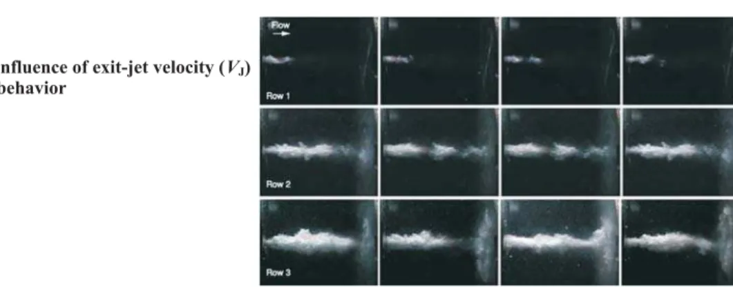
Influence of the cavitation number and exit jet velocity on characteristics of cavitating jets
In order to get better distribution of light so as to improve the quality of images, the flashlight and the camera lens were installed on the same side (same window). Since the window area is not large enough to accept the camera and the flash together in parallel, the flash had to be inclined to the camera direction with an included angleq(in-between 30° and 40°). The experi-mental installation is shown in fig. 1(a). Visualizations were done using convergent nozzles (dout= = 0.4, 0.45, and 0.55 mm) first for different cavitation numberss, which was achieved by chang-ing the downstream pressure (P2) and second for different exit jet velocity (VJ) which was achieved by changing upstream pressure (P1) the other parameters assumed to be constant. Figures 5 and 6 show some images from the results (recorded movies) (fordout= 0.45mm), respectively. The visual analysis of the movies reveals that, the jet appears as a compact, complete solid, and white clouds. The jet penetration is increased assorP2is decreased and when jet strikes the target it starts spreading over the target surface and formation of the characteristic rings is observed. In the first row in fig. 5 the jet did not arrive to the target wall – it disappeared in the region of the sec-ond third of the full distance between the nozzle exit and the target wall (2/3 of standoff distance
Figure 5. Influence of cavitation
x). In fig. 5sRow1> >sRow2>sRow3while in fig. 6VRow2<VRow2<VRow3. The jet is more stable as
VJorP1increase while Jet width and its penetration increased asVJorP1increase. These results are in good agreement with Soyama results [6, 14]. The 3rdrow of images in fig. 6, the gaseous bubbles appear as a fog distributed in the entire chamber.
System arrangement and the information content in cavitating jet images
In order to investigate the influence of arrangement way of the visualization system on the appearance of cavitating jet, two different cases of arrangements has been investigated. In the first case the visualization was made with a sheet of white paper between the flash and the window. The reason for this was to reduce the intensity of light illuminating the jet before enter-ing the camera. In addition, the paper enhances the distribution of the light in the test chamber fig. 1(d) angle between light source and camera lens isj= 180°. In the second case, the visual-ization was made by mounting the flash in such a way to be in parallel with the jet direction (in the same direction of the flow, fig. 1(c) without paper in between). The light was from the other side of the test chamber with the anglej= 90° to the camera lens,i. e. the flash was at right angle to the camera and parallel with jet trajectory. Figure 7 shows the results (2ndand 4thcolumns in each figure for the 1stcase, and 1stand 3rdcolumns for the 2ndcase). The comparison between the two cases reveals that, the position of light and its distribution is very important factor in the in-formation provided by the visualization process for the cavitating jets. In first case the cavitating jet appears as a dark grey shadow. It seems less dense and is discontinuous in some locations. The difference in the jet features compared with the second case may be attributed to the light passing through the jet here, such that the jet appears discontinuous. Also, there exists a reflec-tion process of light by the spherical bubbles in or around the jet. However, this reflecreflec-tion is not
Figure 6. Influence of exit-jet velocity (VJ) on the jet behavior
in the direction of the camera lens, so the camera does not sense the reflected light. All these fac-tors, including the limitation of camera resolution, contribute to the fact that bubbles will not ap-pear in the images and the jet apap-pears as a dark grey shadow. In the second case, and in the pre-vious two cases when flash was mounted as in fig. 1(a, b), the light was reflected by spherical bubbles, thus the distances between the cavitation clouds (or clusters of bubbles), as a result of the break off, could be seen. The rest of the jet appears as a white portion and it contains many tiny bubbles that may reflect some light in the direction of the camera. In fig. 7 atP1= 145 bar, the gas bubbles appear in the images for the second case. However, this was not observed in the firs case. AtP1= 195 bar, the gas bubbles appear in both cases, which may be explained by the appearance of greater number of bubbles at pressureP1= 195 bar than atP1= 145 bar. However, the bubble density (number of bubbles) which appears in the images obtained in the first case is much less than that which appears in the second case. Thus we can notice how the information in the image depends on the arrangement of the visualization system. The interesting point worth mentioning in the end is that the definition of cavitation number (s =P2/P1as proposed by ASTM ) is not enough to describe the phenomenon or is incorrect since the geometry is not in-cluded. The normal definition (s=P2– Pv/0.5 ruref2 ) is more convenient way to describe the phenomenon, even if it is not descriptive enough of the whole phenomenon. However this defi-nition provides values ofs lower when cavitation is more intense which appears reasonable (figs. 5 and 6 are good examples).
Finely the visually analysis of the movies highlighted that, at high injection pressure. The leading part of the main cavitating jet moves gradually toward the direction of impinging target and then shows a shrinking motion in the diameter of cavitating jet near the exit of the nozzle, the peripheral clouds move outward with a shrinking motion and appear to be a string-like vortex cavity with an axis parallel to the target wall surface. The relation between this type of ring-like vortex bubble and the erosion mechanism was presented in previous work [8]. Though the impinging cavitation cloud further develops to a radial direction, the cloud vanish-ing begins to appear near the center of the large cloud region on the wall and rapidly expands to the whole direction to form an annular cloudy zone. This is why the location of collapsing and vanishing clouds in the annular zone is in good agreement with a ring-like erosion distribution [8].
Basic results of computer image processing
The computer image processing was used in order to obtain useful information “mea-sured” to describe the cavitating jet behavior (cavitation clouds). The MATLAB computer soft-ware allows us to analyze an unlimited number of images extracted from recorded movies. As known, the edge detection is identifying points in a digital image at which the image brightness changes sharply or more formally has discontinuities [16]. Sometimes it is a hard task to obtain such ideal edges from real images. Edges extracted from non-trivial images are often hampered by fragmentation, meaning that the edge curves are not connected, missing edge seg-ments as well as false edges not corresponding to interesting phenomena in the image this could be the main error source, thus complicat-ing the subsequent task of interpretcomplicat-ing the im-age data [17] as in fig. 8. The method used to find the edges here is based on the calculation of average pixel values in order to find
old value for each image. Then the image was reduced from colored image to black and white, and then to a binary image. The algorithm assumes that the image contains two classes of pixels (e. g. foreground, cavity) and background (rest of the frame).
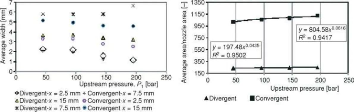
Some properties of the target object (cavitating jet-cavitation cloud), such as area, length, width, were extracted, while in order to see which area in the jet trajectory is changing with time, the software calculated the average pixel value of hundred consecutive images, even the time was big as compared with cavitation changing time (order ofms) and we recorded at 15 frame per secong. From the results shown in fig. 9, one can see that the borders (edges) are in the place where the variation takes place (variation of pixel intensity). This is because of the change of composition in that area (liquid, vapor, or both exist). Even the recording time is so long com-pared with changing time of cavitation phenomenon (µs), still the results in fig. 9 give a general idea about existence of jet oscillation phenomenon which could be estimated using high speed recording system (camera). The comparison between images in fig. 9 shows that the thickness of varied area depends on the geometrical and hydro-dynamical conditions. The variation appears also in the main jet body at high injection pressure. Figure 10 shows the average width of the jet at different positions in the jet trajectory and the average area occupied by jet in the images (hun-dred of images were used under the conditions in table for convergent and divergent nozzle). The results show the effects of geometrical and hydrodynamic conditions on these parameters (area and width).
Figure 9. The most changing parts in the area occupied by the cavitating jet – 1sttwo images (din= 1, dout = 0.45 mm), and 2ndtwo images (din = 0.45, dout= 1 mm), (P1= 45 and 145 bar, tab. 1); image dimensions in mm (for color image see journal web site)
Figure 10. Average area occupied by cavitation, and average jet width as function on upstream pressure, (d
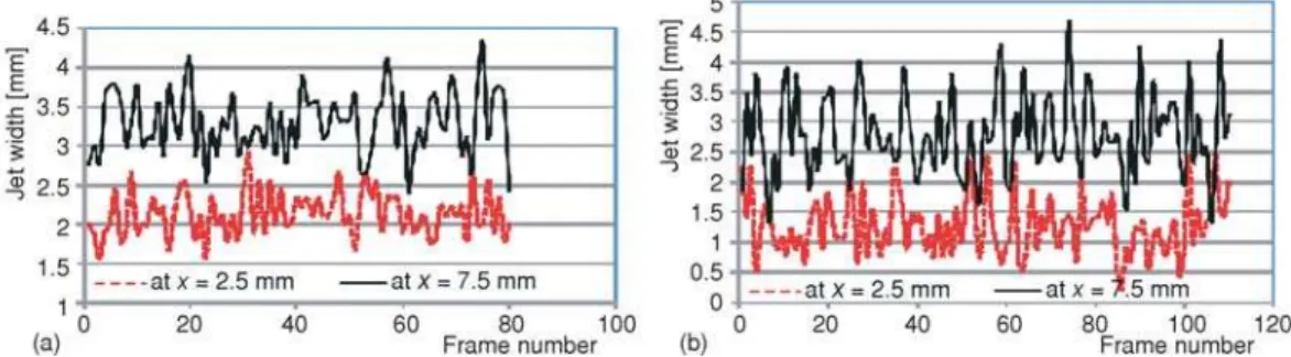
The width was measured at four points along the jet trajectory (only two are presented here). The curves in fig. 11 give general idea about the jet situation at different points along its trajectory, and with time this fluctuation in the thickness is due to the acceleration and deacceleration phenomenon of the cavitating jet or clouds in their movement region (i. e. test chamber), and due to different forces which are acting on the jet periphery, pressure distribution,
etc. In addition the jet produces different cloud sizes, which are the result of growing, shrinking, and collapsing of the clouds during their life stages [11].
Conclusions
The analysis of the movies reveals that, at high injection pressure, the leading part of the main cavitating jet moves gradually towards direction of impinging target and is followed by shrinking motion in the diameter of cavitating jet near the exit of the nozzle. The peripheral clouds move outward with a shrinking motion and appear to be a string-like vortex cavity with an axis parallel to the target wall surface. Though the impinging cavitation cloud further devel-ops to a radial direction, the cloud vanishing begins to appear near the center of the large cloud region on the wall and rapidly expands to the whole direction to form an annular cloudy zone. Because the location of collapsing and vanishing clouds in the annular zone is in good agree-ment with a ring-like erosion distribution, the jet behavior and its features depend on the nozzle mounting (convergent or divergent configuration). The hydrodynamic conditions for cavitation inception and its position depend on the nozzle geometry. The hydrodynamic conditions have strong influence on the jet behavior and its features. Both gaseous and vapour types of cavitation appear at high upstream pressures. The life of gaseous cavitation is longer than of vapour cavita-tion. Vapor types of cavitation depend on cavitation number or on downstream pressureP2, while gaseous cavitation depends mainly on upstream pressureP1. Both of them depend on the nozzle geometry. The visualization arrangement has a significant influence on the quality of jet images, and their content information. The difficulties of capturing the instant of collapsing bubbles are related to inadequate temporal resolution of the illuminating and recording systems, and the large number of the bubbles in the cavitating jet.
Acknowledgment
The authors would like to thank the Ministry of Science Republic of Serbia, for the partial support of this research through the Grant TR35046.
References
[1] Ganippa, L. C.,et al., Comparison of Cavitation Phenomena In Transparent Scaled-Up Single-Hole Die-sel Nozzles, CAV, 2001, session A9.005. http://caltechconf.library.caltech.edu/68/
[2] Vijay, M. M.,et al., A Study of the Characteristics of Cavitating Water Jets by Photography and Erosion, Proceedings, 10th International Conference on Jet Cutting Technology, 1991, pp. 37-67
[3] Yamaguchi, A., Shimizu, S., Erosion Due to Impingement of Cavitating Jet,Transaction of the ASME, 109 (1987), 4, pp. 442-447
[4] Soyama, H.,et al., A New Parameter to Predict Cavitation Erosion,Proceedings, 4thInternational
Sympo-sium on Cavitation California Institute of Technology, Pasadena Cab., USA, CAV, 2001, session A3.002. http://caltechconf.library.caltech.edu/109/I/soyama2.pdf
[5] Zhou, Y. K., Hammitt, F. G., Cavitation Erosion Incubation Period,Wear, 86(1983), 2, pp. 299-13 [6] Soyama, H.,et al., Useful Correlations for Cavitating Jets,The Review of High Pressure Science and
Tech-nology, 7(1998), pp. 1456-1458
[7] Sun, Z., et al., Experimental System of Cavitation Erosion with Water-Jet,Materials and Design, 26 (2005), 1, pp. 59-63
[8] Hutli, E.,et al., Mechanics of Submerged Jet Cavitating Action: Material Properties, Exposure Time and Temperature Effects on Erosion,Archive of Applied Mechanics, 78(2008), 5, pp. 329-341
[9] Karimi, A., Mamouri, M., Deformation Induced by Cavitation Collapse,Proceedings, 7thInternational
Conference on Impact Loading and Dynamic Behaviour of Materials, Bremen, Germany, 1987, pp. 27-1-27-8
[10] Soyama, H., Asahara, M., Improvement of the Corrosion Resistance of a Carbon Steel Surface by a Cavitating Jet,Journal of Material Science Letters, 18(1999), 23, pp. 1953-1955
[11] Hutli, E., Nedeljkovic, M., Frequency in Shedding/Discharging Cavitation Clouds Determined by Visual-ization of a Submerged Cavitating Jet,Journal of Fluids Engineering, 130(2008), 2, pp. 561-568 [12] Keiichi, S., Yasuhiro, S., Unstable Cavitation Behaviour in a Circular-Cylindrical Orifice Flo.,Trans
JSME, International Journal, Ser. B, 45(2002), 3, pp. 638-645
[13] Soyama, H., High-Speed Observation of a Cavitating Jet in Air.,Journal of Fluids Engineering, 127 (2005), 6, pp. 1095-1101
[14] Soyama, H.,et al., Observation of the Cavitating Jet in a Narrow Watercourse,Cavitation and Multiphase Flow, 194(1994), pp. 79-82
[15] Agrawal, A., Prasad, A., Measurements within Vortex Cores in a Turbulent Jet,Journal of Fluids Engi-neering, Transaction of the ASME, 125(2003), 31, pp. 561-568
[16] Zhai, L.,et al., Recent Methods and Applications on Image Edge Detection.Proceedings, International Workshop on Education, Technology and Training & International Workshop on Geo-Science and Re-mote Sensing, IEEE Computer Society, Washington DC, 2008, Vol. 1, pp. 332-335
[17] Lindeberg, T., Edge Detection and Ridge Detection with Automatic Scale Selection,International Journal of Computer Vision, 30(1998), 2, pp. 117-154