July 7–12, 2002, Vienna, Austria Eds.: H.A. Mang, F.G. Rammerstorfer, J. Eberhardsteiner
An Object-Oriented Framework for
Finite Element Programming
Luiz Fernando Martha
Department of Civil Engineering
Pontifical Catholic University of Rio de Janeiro (PUC-Rio) Rua Marquês de São Vicente 225, 22453-900, Rio de Janeiro, Brazil
e-mail: [email protected]
Evandro Parente Junior
Department of Civil Engineering Federal University of Pernambuco (UFPE)
Av. Acadêmico Hélio Ramos s/n, 50.740-530, Recife, Brazil e-mail: [email protected]
Key words: object-oriented programming, finite element method, nonlinear analysis, multi-dimension analysis
Abstract
This work describes an ongoing effort, initiated in early 1990s, in the development of a finite element analysis system, called FEMOOP, based on the object-oriented programming (OOP) paradigm. The over-all class organization of the program will be presented and the main features will be thoroughly discussed. One important feature is the capability of treating multi-dimension finite element models in the same ob-ject oriented, generic fashion. This is accomplished through the definition of two OOP classes: Analysis
Model and Shape. The former is responsible for handling the specific aspects related to the differential
1 Introduction
The application of object-oriented concepts to finite element programming has been receiving great at-tention over the last years [1]. The major advantage of adopting an object-oriented approach is that the program expansion is more simple and natural, as new implementations have a minimum impact in the existing code. Thus, the reuse of code is maximized. Moreover, compared to the classical, structured pro-gramming, the use of the object-oriented programming leads to a more close integration between theory and computer implementation.
The object-oriented programming (OOP) is particularly useful in the development of large and complex programs, as the finite element systems that should handle different element types, constitutive models and analysis algorithms. However, to take full advantage of the object-oriented approach, it is required a thorough understanding of the methodology employed and an extensive effort in program organization.
The aim of this work is to describe an ongoing effort in the development of a finite element analysis system based on the object-oriented programming paradigm. The overall architecture of this system, called FEMOOP, as well as some important classes will be thoroughly discussed. Moreover, some aspects related to the development of the program over the past ten years will also be addressed.
2 Object-Oriented Concepts
The consumer-supplier (or master-slave) paradigm in programming may help understanding the concepts of OOP [2]. The programming activity may be divided in two major roles: a consumer and a supplier. In the present context, a global FEM algorithm may be seen as playing a consumer’s role. For example, the assemblage of the global stiffness matrix requests (as a consumer) the services of specific routines that compute individual finite element stiffness matrices. The routines that compute these matrices are the suppliers to the global algorithm. There are several suppliers, one for each type of finite element.
In a conventional (procedural) programming, the global algorithm is responsible for choosing functions that operate properly on the data that is managed by itself. Therefore, consumer has full visibility to the supplier’s procedures and to the data that is required to perform the actions. Consumer decides how each action has to be performed, calling a specific routine for each type of element. The pseudo-code below illustrates the assembling of a global stiffness matrix in a conventional programming:
ForEachElementInTheModelDo { switch( TypeOfElement ) {
case T3:
ComputeStiffnessT3( dataT3, stiffnessT3 ); AssembleInGlobalMatrix( dataT3, stiffnessT3 ); break;
case Q4:
ComputeStiffnessQ4( dataQ4, stiffnessQ4 ); AssembleInGlobalMatrix( dataQ4, stiffnessQ4 ); break;
case T6:
ComputeStiffnessT6( dataT6, stiffnessT6 ); AssembleInGlobalMatrix( dataT6, stiffnessT6 ); break;
A major problem in this algorithm is that for each new type of element that is created, one case statement has to be added to it. This would happen in all global algorithms that depend on the type of the supplier (element). This means that a common task such as adding a new element type affects the entire program code.
One of the main concepts in OOP, called Encapsulation, changes the consumer-supplier relationship in a global algorithm. Encapsulation means that a consumer sees only the services that are available from a supplier, which in this context is called an object. Therefore, the consumer does not need to know how those services are implemented. As a consequence, only the supplier need to have visibility into the object’s data and to its specific procedures. In a sense, OOP creates a fence protecting the supplier’s data, encapsulating it. The access to specific object’s procedures is performed in a generic and abstract fashion. These generic procedures are called methods. The methods represent the behavior of an object and constitute its external interface.
The pseudo-code of the global algorithm for assembling a global stiffness matrix in an OOP fashion is illustrated below:
ForEachElementInTheModelDo {
elementObj->ComputeStiffness( stiffmatrixObj ); globalmatrixObj->AssembleInMatrix( stiffmatrixObj ); }
In this pseudo-code, ComputeStiffness is a generic method of an abstract element object, while
Assem-bleInMatrix is a method of a global matrix object. The first method returns an abstract stiffness matrix
object, which is passed to the second method. The global algorithm does not have direct access to the object’s data because they are hidden inside the object. The supplier, in this example, has only references to the objects, which will know how to manipulate the appropriate data in their specific implementa-tions of the generic methods. One may observe that the OOP version of the algorithm for assembling a global stiffness matrix does not change at all when a new type of element is created. This is an important characteristic for programs that evolve incrementally such as a finite element analysis program.
The responsibility for choosing the operator (procedure) that is type compatible with the kind of operand (data) has moved from the consumer to the supplier. The consumer decides only which operation has to be performed, calling generically an object’s method. An object, through its class, is responsible for choosing a specific procedure, to consult its data, and to perform the desired action.
In a simplified view, a Class is a set of methods and templates of data. An Object is an instance of a class. Consumer deals only with global algorithms and abstract data types, calling methods (generic procedures) that manipulate objects. Supplier deals with the procedures that implement the methods of a class and its objects. Each object contains a set of state attributes stored in its data.
Another important concept in OOP is Inheritance. This concept is not available in conventional program-ming. Inheritance refers to new classes that inherit methods and data templates. Inheritance is a natural consequence of Encapsulation because the supplier may do any sort of data and procedure manipulation inside its class, as long as it performs a consistent and desired task for the consumer.
need to be copied to the derived class, and modifications in the procedures will automatically affect both classes. Therefore, Inheritance maximizes code reusability.
Another important concept in OOP, called Polymorphism, is a consequence of Inheritance. The consumer may handle instances (objects) of derived classes in the same manner. Thus, the objects of different derived classes are also treated as objects of the base class. For example, in the OOP pseudo-code shown above, all the finite element objects are declared as objects of the most generic base class.
3 Finite Element Programming
Before presenting the class organization of the FEMOOP program it is important to note that the com-putations carried out in a nonlinear finite element analysis occur at three distinct levels: the structure level, the element level, and the integration point level. The structure (or global) level corresponds to the algorithms used to analyze the problem (e.g., linear static, linearized buckling, linear dynamic, nonlinear path-following, and nonlinear dynamic). These algorithms are implemented in terms of global vectors and matrices, and do not depend on the types of elements and materials used in the analysis.
The main task performed at the element level is the computation of element vectors and matrices (e.g., internal force vector and stiffness matrix) required to assembly the global vectors and matrices, which are used by the analysis algorithms. The computation of these vectors and matrices is completely inde-pendent of the algorithm used to (globally) analyze the model.
The communication between the global and the element level occurs in the two directions. The upward direction corresponds to the computation of the global vectors and matrices summing up the element contributions, and the downward direction corresponds to the extraction of the element displacements from the global displacement vector. These communications tasks are carried out using nodal degrees of freedom and element connectivity.
Finally, the computation of stress vector and tangent constitutive matrices is carried out at the integration point level. These quantities are used in the computation of the element vectors and matrices, but they do not depend on the element formulation, provided the basic input data for stress computation are strain components.
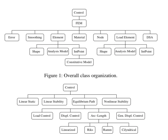
4 The FEMOOP System
The overall class organization of the FEMOOP system is depicted in Figure 1, where all shown rela-tionships are of type “has a.” According to the previous discussion, the global level is represented by the Control and Finite Element Model (FEM) classes, as well as by the three post-processing classes:
Smoothing, Error, and Design Sensitivity Analysis (DSA).
Control is an abstract base class that provides a common interface for the algorithms used to analyze
the problem, while each particular algorithm is a derived class that implements specific methods such as
Initialize (to compute the nodal d.o.f., the number of equations, etc.) and Solve (to execute the required
analysis procedure). The current hierarchy of the Control class is shown in Figure 2. The relationships in this hierarchy are of type “derived from.” It can be seen that until now much of the work has been focused on nonlinear analysis of static problems, which is performed by the Equilibrium Path class.
Element Material Node Load Element
Analysis Model IntPoint
Shape Shape Analysis Model IntPoint
Constitutive Model Smoothing
Error DSA
FEM Control
Figure 1: Overall class organization.
Linear Static Linear Stability Nonlinear Stability Control
Displ. Control Arc−Length Gen. Displ. Control Load Control
Ramm
Riks Cilyndrical Linearized
Equilibrium Path
Figure 2: Control class hierarchy.
to a list of objects of Element class (the elements of the mesh), to a list of objects of Material class (the different materials used in the model), and to a list of objects of Load Element class (fictitious elements that transfer the natural boundary conditions from elements to nodes).
The main tasks of the Finite Element Model class are to compute the nodal d.o.f., to assemble the global vectors and matrices used by the analysis algorithms, to update nodal displacements, and to print com-puted results after convergence. Moreover, during the result computation it also calls, if necessary, the methods of the post-processing classes: Smoothing, Error, and Design Sensitivity Analysis, which are used for stress smoothing, discretization error assessment, and sensitivity computation, respectively.
Node class basically stores the nodal data read from the input file (coordinates, springs, support
condi-tions, and concentrated loads), as well as some variables computed during the program execution, as the nodal d.o.f. and the current displacements. It also provides a number of methods to query and to update the stored data.
Material is an abstract base class that provides a generic interface to handle the different materials
(derived classes) available in the program, which includes some elastic (e.g., isotropic, Cosserat, and Winkler foundation), and elasto-plastic materials (e.g., Tresca, von Mises, Mohr-Coulomb, and Drucker-Prager). The basic objective of these classes is to store the material properties read from an input file and to provide a number of methods to query these properties.
Element is an abstract base class that defines the generic behavior of a finite element. The main tasks
performed by an object of the Element class are the indication of the number and direction of the active nodal d.o.f., the computation of the element vectors (e.g., internal force) and matrices (e.g., stiffness matrix), and the computation of the element responses (e.g., stresses).
exten-Frame 3D Plane Frame
Corotational Condensed Tot. Lagrang. Parametric Truss 3D
Corotational Tot. Lagrang.
Element
2 D 3 D Shell
Figure 3: Element class hierarchy.
sive use of Inheritance and Polymorphism has been carried out, allowing a great amount of code reuse. To give an example, the geometrically nonlinear elements were implemented through the derivation of the basic element classes, avoiding the reimplementation of the linear terms. The implemented features include continuum, bar (trusses and frames), and shell elements (2D and 3D integration). It is important to note that a number of elements derived from the Parametric class (e.g., DKT and DKQ plate elements) and Shell 3D class (e.g., Huang-Hinton and MITC4 elements) were not shown in Figure 3 to keep the presentation clear.
One important characteristic of the FEMOOP system is the capability to handle multi-dimensional fi-nite element models in the same object-oriented generic form. To explain the adopted approach, it is interesting to consider the computation of the stiffness matrix ( ) of a linear continuum element:
✂✁☎✄✝✆✟✞✡✠✝☛☞✞✍✌✏✎✑✒✎✔✓✖✕✗✁✙✘✛✚✜
✢
✚✤✣✦✥✖✧
✞✡✠✝☛☞✞✍✌✏✎✑✒✎★
✚✪✩✫✚✭✬
(1)
where✞
is the strain-displacement matrix, ☛
is the constitutive (stress-strain) matrix, ✎✑✒✎
is the determi-nant of the Jacobian matrix, ✌
is a coefficient related to the differential volume of the element (e.g.,✌
is equal to the element thickness for plane stress problems), and
✩
is the weight of the integration point. It should be noted that the form of this equation does not dependent on the element dimension (1D, 2D, or 3D), shape (triangular, quadrilateral, hexahedral, etc.), and interpolation order (linear, quadratic, or cu-bic). Moreover, it is also independent of the particular differential equation (and of the related variational statement) that governs the element behavior. To handle the different finite elements in a generic form, each object of the Element class has references to objects of three important classes: Shape, Analysis
Model, and Integration Point.
Shape class holds the geometric and field interpolation aspects of the element (dimension, shape, number
of nodes, nodal connectivity, and interpolation order). It is an abstract base class that defines the generic behavior of the different derived classes implemented in the program, which includes a number of 1D, 2D, and 3D parametric shapes with different interpolation orders. Shape class and its derived classes provide methods to query the number of nodes and the element connectivity, to compute the shape functions and their derivatives with respect to parametric coordinates, and to evaluate the Jacobian matrix and the shape functions derivatives with respect to Cartesian coordinates.
On the other hand, Analysis Model class handles the aspects related to the differential equation that governs the problem to be solved. It is an abstract base class that defines the generic behavior of the different models implemented in the program, as the truss, frame, plane stress, plane strain, axisymmetric solid, Winkler foundation, thin and thick plate, thick shell, and 3D solid models. Analysis Model derived classes provide methods to query the number and nature of the active nodal d.o.f., as well as the number and nature of the stresses/strains involved. They also provide methods to compute the ✌
to assemble the ☛
and ✞
matrices (and other matrices necessary to deal with geometrically nonlinear problems), and to compute principal and equivalent stresses.
Finally, each Integration Point object holds the parametric coordinates and the corresponding weight used for the numerical integration. Consider now the computation of the internal force vector ( ), required for a nonlinear analysis. For materially nonlinear problems, this vector can be written as
✁ ✄✝✆ ✞ ✠✂✁ ✌✏✎✑✒✎✔✓✖✕ ✁ ✘✛✚✜ ✢ ✚✤✣✦✥ ✧ ✞ ✠✂✁ ✌✏✎✑✒✎★ ✚✪✩✫✚✭✬ (2)
where the stress vector (✁
) is computed from the current strain vector (✄ ). According to the above
ex-pression, the stresses need to be computed at each integration point. To perform this task, each object of the Integration Point class has a reference to an object of the Constitutive Model class.
Constitutive Model is an abstract base class that provides a common interface to the different constitutive
relations implemented in the program, which include the linear elastic model, some nonlinear Winkler foundation models, as well as different plasticity and damage models. The main methods of Constitutive
Model derived classes are the computation of the stress vector for a given strain vector and the evaluation
of the tangent
☛
matrix, to be used in equation (1), from the initial
☛
matrix and the current stress/strain state. It should be noted that for plasticity and other models the stresses depend not only on the current stress state, but also on the loading history. Therefore, some Constitutive Model derived classes store a set of internal variables (e.g., plastic strains) and provide a method for update these variables after the convergence of the path-following algorithm.
Load Element class was created to allow the generic consideration of natural boundary conditions and
body forces. It is an abstract class that provides a common interface for the different loading conditions considered in the program. Moreover, this base class also implements the computation of consistent nodal load vectors, and the application of the computed loads in the appropriate degrees of freedom.
Equation (3) illustrates the contribution of an element to a consistent nodal load vector (☎ ). The
contri-bution of a distributed load (✆ ) applied at the boundary (✝ ) of a continuum element can be computed
from: ☎ ✁☎✄ ✞ ✟ ✠ ✆ ✌✏✎✑✒✎✔✓ ✝ ✁ ✘✛✚✜ ✢ ✚✤✣✦✥✖✧ ✟ ✠ ✆ ✌✏✎✑✒✎★ ✚✝✩✫✚✭✬ (3) where ✟
represents the matrix of the interpolation functions in the loaded boundary. As equation (1), the form of this equation is independent of the element dimension, shape, interpolation order, and of the differential equation of the particular problem. To perform this type of generic computation, each
Load Element object has references to one Shape object, to one Analysis Model object, and to a list of Integration Point objects.
The Shape object in this computation is responsible for the computation of shape functions and of ✎✑✒✎
, the
Analysis Model object performs the assemblage of the✟
matrix and the computation of the✌
coefficient, while the Integration Point objects are used for the numerical integration of the equivalent nodal loads. The appropriate Shape object is automatically created by the program based on the type of the Load
Element (e.g., side load, surface load, and volume load) and on the Shape of the parent Element. Finally,
it should be noted that the computation of the✆ vector is performed by a method defined by each Load
Element derived class, and that these classes can also redefine the computation of the load vector in order
4.1 Historical note
The design and implementation of the FEMOOP system was initiated in early 1990s. Due to the lack of standardization of the early versions of the C++ language, which compromises the portability of the program, the implementation of the first version was performed in the C language using a discipline of object-oriented programming [3, 4]. As this version was dedicated only to the linear structural analy-sis, the attention was focused in the formulation of classes to compute the stiffness matrix of different elements in a generic form. To this aim, classes Element, Analysis Model, Material, and Gauss (lately substituted by Integration Point) were created.
A major enhancement in the C version of the program was performed to allow the solution of heat transfer problems in the steady-state and transient conditions [5]. Thus, an Algorithm class (lately substituted by
Control class) was created to handle the different analysis procedures, while the Shape and Load Element
classes were created to allow the generic computation of the external load vector for different loading conditions (distributed forces, heat flow, etc.). Finally, in order to use the program for adaptive analysis, an Error class was created to compute the discretization errors using different smoothing procedures [6, 7].
The C version was important to validate the use of the object-oriented concepts in the finite element programming. However, the lack of a formal mechanism for implementing Inheritance, Polymorphism, and Encapsulation in the C language, was recognized since the beginning as a major drawback of this approach. As the structure of C++ language became more stable, and its compilers more efficient and available at different computer platforms (e.g., PCs, Unix workstations), a shift from C to C++ was performed.
This occurred at the same time that the program was expanded to deal with the materially nonlinear problems [8]. These efforts resulted in the creation of the Node class, in modifications in the Gauss class, and in the creation of the Constitutive Model class. Moreover, the Algorithm class was eliminated and substituted by the Control class, that handles the different solution procedures, as well as the Finite
Element Model class that computes the global vectors and matrices used by the Control class. Finally, the Equilibrium Path class was created as a derived class of the Control class in order to handle the different
path-following methods implemented in the program.
FEMOOP system has been used as the computational platform for different researches, including the modeling of strain localization using generalized continuum theories [9], the nonlinear analysis of crete structures including size effects and heterogeneity [10], the shape optimization of nonlinear con-tinuum structures [11], the adaptive analysis and shape optimization of free-form shells [12], and the analysis of plates with unilateral contact constraints [13]. These implementations resulted in the substi-tution of the Gauss class by the Integration Point class (including other integration schemes) and in the creation of the Design Sensitivity Analysis class to carry out the shape sensitivity computation.
FEMOOP has also been modified to implement parallel analyses, which can be performed using two dif-ferent techniques: a domain decomposition technique or an element-by-element scheme [14, 15]. Finally, the implementation of dynamic analysis is currently under way [16].
5 Concluding Remarks
of the FEMOOP project was to devise a basic computational platform to be used in research works developed in the Department of Civil Engineering of PUC-Rio and in the Computational Mechanics Laboratory, Polytechnic School, University of São Paulo.
The object-oriented programming paradigm was adopted due to the intrinsic incremental nature of the de-velopment of such a system, and to the increasing complexity of the program as new features (elements, constitutive models, and analysis algorithms) are incorporated in the system. Moreover, as discussed in the previous sections, the use of the object-oriented programming leads to a more close integration between the finite element theory and the computer implementation, improving the program understand-ability and easing the system documentation.
Now, with more than ten years from the beginning, it is possible to say that the FEMOOP project is a succesful initiative, and that the use of the object-oriented techniques in finite element programming brings real benefits. The experience with the FEMOOP development confirmed that the use of the OOP paradigm strongly increases the system extendability and promotes code reuse. However, it should be recognized that to obtain these benefits it is necessary a detailed study of the problems that need to be solved and a careful work in the program organization.
The experience with the FEMOOP development has been shown that a well-designed class organization accommodates the implementation of a large amount of new features in the program with none or only minor changes in this organization. Moreover, the vast majority of the new implementations performed in the system are the creation of derived classes from existing base classes or the creation of new methods in existing classes. As a consequence, changes in the overall class organization are very rare.
However, this does not imply that the class organization has to be totally created before the program implementation. In fact, the process adopted in the FEMOOP development was exactly the opposite, with the class organization evolving as new features were included in the system, demonstrating that the OOP is really adequate to the incremental developing, which is inherent to complex systems as the finite element programs.
Acknowledgements
The first author acknowledges financial support by CNPq (Project 300.483/90-2). The authors are great-ful with the researchers that contributed in the FEMOOP development (in alphabetical order, among others): Áurea S. Holanda, Carlos Vitor Alencar, Célio O. Moretti, Deane Roehl, Eduardo S. Silveira, Eduardo N. Lages, Estela M. R. Bueno, Gilson Fujji, Ivan F. M. Menezes, Januário Pellegrino Neto, João B. M. Souza Jr., João L. E. Campos, Joaquim B. Cavalcante Neto, Júlia C. P. Barros, Luiz Gil S. Guimarães, Marcelo Frydman, Nick Lehtola, Reynaldo T. Lima, Roque L. S. Pitangueira, Tereza D. P. Araújo, Túlio N. Bittencourt, William W. M. Lira.
References
[1] J. Mackerle, Object-oriented techniques in FEM and BEM, a bibliography (1996-1999), Finite Elements in Analysis and Design, 36, (2000), 189–196.
[3] L. G. S. Guimarães, Object-Oriented Programming Discipline for Analysis and Visualization of
Two-dimensional Finite Element Models, Master’s thesis, Department of Civil Engineering,
PUC-Rio, Brazil (1992), in portuguese.
[4] L. G. S. Guimarães, I. F. M. Menezes, L. F. Martha, Object-oriented programming discipline for
finite element systems, in Proceedings of the XIII CILAMCE, Porto Alegre (1992), pp. 342–351, in
portuguese.
[5] J. C. P. Barros, Thermal Analysis by the Finite Element Method Implemented through an Object
Oriented Philosophy, Master’s thesis, Department of Civil Engineering, PUC-Rio, Brazil (1994),
in portuguese.
[6] J. B. Cavalcante Neto, Self-Adaptive Simulation based on Recursive Spatial Enumeration for
Two-dimensional Finite Element Models, Master’s thesis, Department of Civil Engineering, PUC-Rio,
Brazil (1994), in portuguese.
[7] G. H. Paulino, I. F. M. Menezes, J. B. C. Neto, L. F. Martha, A methodology for adaptive finite
element analysis: Towards an integrated computational environment, Computational Mechanics,
23(5/6), (1999), 361–388.
[8] L. F. Martha, I. F. M. Menezes, E. N. Lages, E. Parente Jr., R. L. S. Pitangueira, An OOP class
orga-nization for materially nonlinear FE analysis, in Proceedings of Joint Conference of Italian Group of Computational Mechanics and Ibero-Latin American Association of Computational Methods in Engineering, Padova, Italy (1996), pp. 229–232.
[9] E. N. Lages, Strain Localization Modeling using Generalized Continuum Theories, Ph.D. thesis, Department of Civil Engineering, PUC-Rio, Brazil (1997), in portuguese.
[10] R. L. S. Pitangueira, Analysis of Concrete Structures Including Size Effects and Heterogeneity, Ph.D. thesis, Department of Civil Engineering, PUC-Rio, Brazil (1998), in portuguese.
[11] E. Parente Jr., Sensitivity Analysis and Shape Optimization of Geometrically Nonlinear Structures, Ph.D. thesis, Department of Civil Engineering, PUC-Rio, Brazil (2000), in portuguese.
[12] J. B. M. Souza Jr., Adaptive Analysis and Shape Optimization of Free-Form Shells, Ph.D. thesis, Department of Civil Engineering, PUC-Rio, Brazil (2000), in portuguese.
[13] A. S. Holanda, Analysis of the Equilibrium and Stability of Plates with Contact Constraints, Ph.D. thesis, Department of Civil Engineering, PUC-Rio, Brazil (2000), in portuguese.
[14] C. O. Moretti, J. B. C. Neto, T. N. Bittencourt, L. F. Martha, A parallel environment for
three-dimensional finite element analysis, in B. Topping, ed., Developments in Engineering Computa-tional Technology, Civil-Comp Press (2000), pp. 283–287.
[15] C. O. Moretti, A Parallel System for Simulation of Three-Dimensional Crack Propagation, Ph.D. thesis, Department of Structural and Foundation Engineering, University of São Paulo, Brazil (2001), in portuguese.
[16] J. Pellegrino Neto, Nonlinear Dynamic Analysis and the Orthogonal Projection Method: Finite
Element Formulation and Object-Oriented Implementation, Ph.D. thesis, Department of Structural