UNIVERSIDADE NOVA DE LISBOA
Faculdade de Ciências e Tecnologia Departamento de Engenharia Electrotécnica
REAL TIME MOBILE SYSTEM FOR SUPPORT IN FIREFIGHTING
ENVIRONMENTS
Por:
João Reis Costa Mendes
Dissertação apresentada na Faculdade de Ciências e Tecnologia da Universidade Nova de Lisboa para a obtenção do grau de Mestre em Engenharia Electrotécnica e de Computadores
Orientador: Prof. Doutor José Manuel Fonseca Co-Orientador: Prof. Doutor Pedro Manuel Vieira
i
Abstract
This dissertation addresses work being performed within the context of the Fire Forest Finder system, fulfilling the requests for a multi-information application intended for a vehicle mounted mobile device.
The main objective of this dissertation is to provide a solution running on a PDA device that provides support in Fire Fighting environments. The user has access to: multi-information data of the theater of operations, an automotive navigation system (TomTom Navigator™) and a text messaging capability.
The hardware present on this system is a DLoG X7™ industrial graded PDA that possesses the right sturdiness for this task. The software developed consists of three distinct interfaces: an appropriately customized TomTom Navigator™ interface for the end-users of this system and two additional applications were created to allow a proper visualization of the available information and also have an interface with text messaging input/output capabilities;
It is important to refer that the GSM protocol, text messaging service in particular was the chosen communication mean due to the fact that this network has, at the time this dissertation was finished, the better and most reliable coverage of remote areas, such as the forests for which this system is intended to.
In terms of experimental validation a series of performance, intuitiveness and usability tests were performed and analyzed in detail with the purpose of demonstrating the validity of the ideas presented.
The thesis is completed by the depiction of the achieved results with the subsequent discussion and identification of open points as a result of the work done.
Keywords
iii
Resumo
No âmbito do sistema Forest Fire Finder esta dissertação tem como objectivo apresentar um sistema de processamento de multi-informação destinado a ser usado num dispositivo móvel montado num veículo.
O principal objectivo deste trabalho é providenciar uma aplicação de software a correr num PDA de modo a prestar um apoio fundamental em ambientes de combate aos incêndios. Neste sistema o utilizador tem acesso a uma panóplia de informações provenientes do teatro de operações, a um sistema de navegação automóvel (TomTom Navigator™) e à capacidade de comunicação por mensagens de texto.
O hardware presente neste sistema é o PDA industrial DLoG X7™ que possui as características de robustez apropriadas para este tipo de ambientes. Em termos do software desenvolvido o sistema é composto por três interfaces distintas: uma interface do TomTom Navigator™ personalizada para os utilizadores finais deste sistema; e duas interfaces que providenciam respectivamente, uma visualização adequada da informação do teatro de operações disponível e uma capacidade de recepção e emissão de mensagens de texto.
Como meio de comunicação do sistema com o exterior é importante salientar que o protocolo escolhido foi o GSM, com ênfase no serviço de mensagens de texto, devido ao facto de até à altura da conclusão da escrita desta dissertação, nenhum outro meio conseguir garantir uma cobertura desta qualidade ao nível de áreas remotas como é o caso das florestas no sistema desenvolvido nesta dissertação.
Em termos de validação experimental foram efectuados vários testes de performance, ergonomia e facilidade de uso, tendo em vista uma análise detalhada que procurou demonstrar a validade das ideias apresentadas.
A dissertação termina com a apresentação dos resultados conseguidos seguida de uma discussão e identificação dos vários pontos em aberto no que concerne ao trabalho efectuado.
Palavras-Chave
v
Acknowledgments
To begin my acknowledgments I would like, first and foremost, to thank my family, for all their endured sacrifices that made possible for my graduation and the comfort, encouragement and affection they have always demonstrated through all these years.
I thank Prof. Pedro Vieira for the orientation, ever-present support and patience to guide my progression even when I felt lost at times. I would like to thank him specially for making all the human and physical resources at NGNS-IS always available for my support; and also, for all the text revision, for this dissertation and the elaborated scientific paper.
To Prof. José Manuel Fonseca, for the co-orientation and the opportunity that was given to be part of this project. I thank you for all the advices, support and the careful revision of the text for this dissertation.
I would like to thank all the people at NGNS-IS that helped me on the course of this dissertation, specially Nuno Pinto, Pedro Duque and Manuela Contrim, without your help and support I would not have been able to pulled this off!
To Mr. Franz Angermeier and the DLoG company for providing essential assistance in solving specific problems that rose during the course of this dissertation.
A very special thank you goes to all my friends and colleagues, for their advice, for their comprehension, understanding, and patience to put up with me through this long process, it was worth it!
vii
Table of Contents
Chapter 1. ... 1
1.1 Background ... 1
1.2 Introduction ... 2
1.3.Objectives and Contributions ... 4
1.4 General Overview of the Dissertation ... 5
Chapter 2. ... 8
2.1 HARDWARE – DLoG X7 ... 8
2.1.1 DLoG X7 Overview ... 8
2.1.2 Operating System ... 10
2.2 SOFTWARE – TomTom ... 11
2.2.1 TomTom Navigator ... 11
2.2.2 Software Development Kit ... 12
2.3 SOFTWARE – Server Backoffice ... 13
2.3.1 SMS Protocol ... 14
Chapter 3. ... 16
3.1. Introduction ... 16
3.2. Windows Messages ... 18
3.3. MAIN Application ... 22
3.3.1 Main Class – Global Algorithm ... 22
3.3.1.1 Hardware Control ... 23
3.3.1.2 Message Routing between Threads and Applications ... 29
3.3.1.2.1 Between Applications ... 30
3.3.1.2.2 Between Threads ... 31
3.3.2 Auxiliar Classes – Algorithms ... 38
3.3.2.1 GSM Communication ... 38
3.3.2.2 Event Processing ... 40
3.4 SMS Application ... 49
viii
3.4.2 Alphanumeric Keypad handling ... 50
3.4.3 Text message traffic handling ... 52
3.5 Tracking, Robustness/Ruggedness and Control Files ... 53
3.5.1 Global Log ... 55
3.5.2 GSM Log ... 56
3.6 Interfaces ... 57
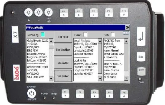
3.6.1 FFFpdaMAIN ... 58
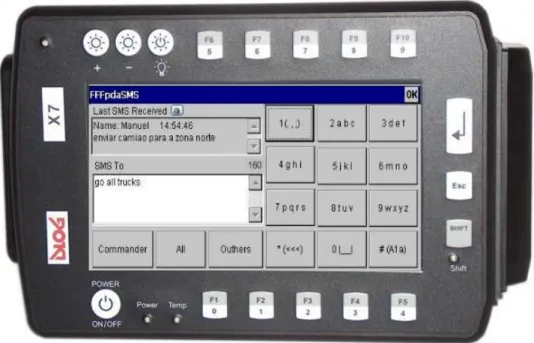
3.6.2 FFFpdaSMS ... 58
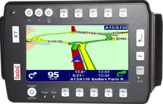
3.6.3 TomTom Navigator Customized ... 59
3.6.4 Administrator Mode ... 61
Chapter 4. ... 62
4.1 Description of the Simulation Environment and Vehicle ... 63
4.2 Tests ... 66
4.2.1 Road-Book Test ... 66
4.2.2 System Usability ... 71
4.2.2.1 TomTom ... 72
4.2.2.2 Assorted Actions ... 74
4.2.2.3 Overall Appreciation ... 74
4.2.2.4 Suggestions ... 75
4.3 Conclusions ... 75
Chapter 5. ... 78
5.1 General Summary ... 78
5.2 Conclusions ... 78
5.3 Future Work ... 79
REFERENCES ... 81
Appendix - A. ... 83
Appendix - B. ... 87
Appendix - C. ... 93
Appendix - D. ... 95
ix
Acronyms and Abbreviations
API Application Programming Interface CAB Cabinet (file format)
CPU Central Processing Unit FFF Forest Fire Finder
GIS Geographic Information System GPS Global Positioning System GPRS General Packet Radio Service
GSM Global System for Mobile Communication MCC Mobile Control Center
OEM Original Equipment by Manufacturer OS Operating System
PDA Personal Digital Assistant PIN Personal Identification Number POI Point of Interest
RAM Random Access Memory
ROM Read Only Memory
SIM Subscriber Identity Module SMSC Short Message Service Center
SMS Short Message Service
SDK Software Development Kit
TT TomTom™
TTN TomTom Navigator™
USB Universal Serial Bus
xi
List of Figures
Figure 1.1 – FFF system overview………..1
Figure 1.2 – Interfaces……….…..4
Figure 2.1 – DLoG X7………..……..….8
Figure 2.2 – Win CE Architecture……….….….9
Figure 2.3 – A complete coded event………13
Figure 3.1 – Global system architecture………16
Figure 3.2 – TTN interface………..……..17
Figure 3.3 – Main interface……….…..17
Figure 3.4 – SMS interface………...….….17
Figure 3.5 – System defined messages………..…...18
Figure 3.6 – Custom application defined messages………..20
Figure 3.7 – Edit boxes scrolling hardware keys………..24
Figure 3.8 – Application selection hardware keys………26
Figure 3.9 – TT events Show/Hide hardware keys………...……27
Figure 3.10 – SMS to MAIN message process……….30
Figure 3.11 – MAIN to SMS message process……….…………31
Figure 3.12 – Outgoing message processes………..………32
Figure 3.13 – Incoming message processes………..………33
Figure 3.14 – System crash message process………..….……34
Figure 3.15 – Start position timer and SMS thread message process………..……….…35
Figure 3.16 – Global Log message process……….….…36
Figure 3.17 – GSM Log message process………...….…36
Figure 3.18 – Fire event detail……….……39
Figure 3.19 – Weather event detail……….………….40
Figure 3.20 – Auto event detail………...……….…40
Figure 3.21 – Water event detail……….…….……40
Figure 3.22 – Human event detail………...……….……41
Figure 3.23 – Invalid Water event………..……….…44
Figure 3.24 – Track Position Update system message………47
Figure 3.25 – System Crash system message………..………48
Figure 3.26 – Alphanumeric keypad………...………49
Figure 3.27 – Invalid event response message………53
Figure 3.28 – Fire event log entry………...…55
Figure 3.29 – Invalid event log entry………..……55
Figure 3.30 – Auto-Refresh log entry……….…55
Figure 3.31 – GSM log entry types………56
Figure 3.32 – FFFpdaMain interface………..…57
Figure 3.33 – FFFpdaSMS interface………..……58
Figure 3.34 – TTN main interface………...…59
Figure 3.35 – TTN browse interface with events………...……59
Figure 3.36 – Customized TTN main menu………...………60
xii
Figure 4.1 – Complete simulation environment………63
Figure 4.2 – Nokia 6020 mobile phone……….…63
Figure 4.3 – Vodafone SMS webpage………...…..64
Figure 4.4 – The used vehicle mounted with the DLoG………...…....64
Figure 4.5 – TT Default Screen………...67
Figure 4.6 – TT interface options………..…....67
Figure 4.7 – FFFpdaMAIN interface options………....…….…..68
Figure 4.8 – TT Event warning message flash……….……….…68
Figure 4.9 – Show/Hide Events keys………..………...69
Figure 4.10 – SMS interface……….………70
Figure 4.11 – SMS dialog……….………...…… 70
Figure 4.12 – Confirm the reception of multiple Events………..…….…………71
Figure 4.13 - Trace a route to a Water event………..……...………71
Figure 4.14 – Go to specific Fire event location………...……….…72
Figure 4.15 – Show/hide Auto event………..……..……….72
Figure 4.16 – Confirm the reception of a SMS and reading of the last two received SMS messages………..…...72
Figure 4.17 – See Weather event detailed information………...72
Figure 4.18 –Send a SMS Message to “All”………...…....73
Figure 4.19 – Turn Off the DLoG………...……...…73
Figure 4.20 – Reboot the DLoG………73
Figure 4.21 – Overall Appreciation……….…….……74
Figure B.1 – DLoG X7……….………….….………...87
xiii
List of Tables
Table 2.1 – Event/Code conversionable………...……….13
Table 2.2 – SMS Protocol………...…...14
Table 3.1 – TT events Show/Hide keys……….………27
Table 3.2 – Events struct type and array size correspondence………...………...…41
Table 3.3 – Event/Occurrence types………...45
Table 3.4 – Event/Occurrence TT screen messages………...………....46
Table 4.1 – Road-Book guide……….…..…66
Table A.1 - Event/code message types……….……..……..….…83
xv
List of Algorithms
Algorithm 3.1 – Main class global……….………22
Algorithm 3.2 – Hardware control……….…23
Algorithm 3.3 – Scroll UP……….……25
Algorithm 3.4 – Application selection………...……26
Algorithm 3.5 – TT All Events Show/Hide………..………28
Algorithm 3.6 – GSM communication………..………38
Algorithm 3.7 – Event class global………42
Algorithm 3.8 – Incoming Event………..…….……43
Algorithm 3.9 – Process Event………..………44
Algorithm 3.10 – Outgoing Event………...………..………47
Algorithm 3.11 – SMS class global………..….……49
Algorithm 3.12 – Alphanumeric keypad handling………50
Algorithm 3.13 – Keypad value rotating……….…..………51
1
Chapter
1.
I
NTRODUCTION
1.1
Background
Technology in the last years has seen an exponential growth and has helped to provide solutions on many levels in different areas. A common objective rises: provide tools which help the human decision process, specifically in the case of this dissertation regarding a real time situation based on a multitude of available data at each moment.
Forest fire is a scourge that affects many countries and the last years have been a testimony of this situation. Once the Fire has been detected the swiftness of the reaction and response times are essential in order to minimize the damages. An optimized access to all the available information related to the theater of operations is fundamental to improve the quality and the speed of the decision process.
To respond to this problem, NGNS – Ingenious Solutions™ has developed the Forest Fire Finder™ (FFF), an innovative system of forest fire detection and location. It provides forests owners with an honest reliable system that is human independent, given its autonomous and automatic character and insures a decrease of response time to the emergency [NGNS-IS 2009] .
2
In this context rises the need for a system that has the following characteristics: capability of accurately showing the precise location of fires, other vehicles and water supplies; providing visualization of real-time periodic data from each of the referred elements; show instant detailed meteorological data and that could also be used as communication medium by means of a simple and reliable text-messaging system.
1.2
Introduction
Following the analysis of the problematic previously enunciated, the theme of this dissertation became a challenge of developing a user-friendly application which runs on industrial graded Personal Digital Assistants (PDA) adequate to the harsh environmental conditions. This system should supply the user with multiple real time data from the global fire scenario and provide communications through the Short Message Service (SMS) text messaging system.
Some solutions have been tried in the past, the most similar consisted on a hand-held mobile device approach to disaster management, based its communications in a continuous Global Communication for Mobile Communications (GSM) data-link. Due to cost and technology limitations at the time, this project was not pursued. [Fischer 2000]. The key difference to the work developed in this thesis, is the fact that instead of relying on a continuous stream of data being passed constantly to send maps, images, text, the present system offers a more efficient and cost-effective solution. By using a navigational software that provides the map visualization needed and the inherent routing tool, this method allows all the information needed to be passed exclusively by coded text messages which will be interpreted appropriately.
3 industry [FMSy 2009]. The work developed for this dissertation combines the features of the previous mentioned examples in a unique decision support system that has the following key features: improve response time through a navigational software, provide the Firemen with a visual scenario of the theater of operations, and also update this information in real-time. Mobility on the case of this dissertation is fundamental, so the system was designed to be used in a vehicle mounted PDA device, with simple and intuitive interfaces in order to simplify the task of the Firemen. As an alternative to the common radio communications, text messaging capability is provided which can be used as an alternative broadcasting medium.
The innovation that this system proposes is to provide a mobile tool to aid the decision process, specifically, on a Fire scenario maintaining an easy and simple interaction with the Firemen. This design objective modeled the visual and interactive features of the system interfaces, providing the Firemen with an intuitive presentation of the real-time available information combined with map visualization.
The first task was to choose an adequate PDA for the problematic in hand and the decision was to have a fixed robust device on the vehicle instead of a portable handheld one. This is justified by the need for a more ergonomic firemen oriented device that could support the abuse of the physical (temperature, pressure, impact) conditions which are common inside a firefighting vehicle. In accordance to several factors, explained latter on this thesis, the DLoG X7™ was chosen.
The second concern was to decide whether to implement a Global Positioning System (GPS) navigational software, or on the other hand resort to one of the currently available on the market, that could provide the capabilities that the project required. A careful investigation on the status quo of the navigational software paradigm was performed. Taking in account that the main objective of this dissertation is the creation of an application that, above all features provides, the most quantity of useful data to the firefighter, the decision was made not to develop a navigational software. So TomTom Navigator™ 6.010 (TTN) was chosen as the software to be used. The downside of this decision is that newer versions of the TTN could not be used due to the limitations of the PDA hardware operating system (OS), Microsoft Windows CE 5.0™ (WinCE). This will be discussed in detail later in this dissertation.
4
Microsoft Visual Studio 2005 suite. The debugging process was performed by deploying and remote debugging the several applications on the PDA X7 itself, due to the fact that the TT SDK do not allow for the use of an emulator.
Having set the base for our application, both hardware and software aspects, the next decision was to divide the application into three interfaces that can be accessed through hardware buttons: “TTN”, “Main” and “SMS” – Figure 1.2. There is an additional administrator override option which closes the running applications and brings up the standard WinCE interface and all its inherent capabilities.
Figure 1.2 –Interfaces
1.3 Objectives and Contributions
This dissertation deals with the work being performed in the context of the FFF project, but standing as an independent yet globally integrated module that seamlessly interacts with the existent platform.
The specific objectives of the project addressed in this dissertation dealt by the author are the following:
Research on the PDA, DLoG X7™ device and all its hardware possibilities from the perspective of the end-user, in this case the firemen.
Develop a Text Messaging protocol that carries all the communications with the backbone server, from the Global System for Mobile Communication (GSM) module signal reception, to a higher message processing level
5 Implementation of a robust, error free system that after a reboot in case of an anomalous error or system failure, could be brought up-to-date automatically. Exhaustive study of TTN 6 and the provided SDK.
The main contribution of this dissertation is to provide within the Firefighting paradigm a useful, user-friendly tool that hopefully allows a faster and more precise response to a fire scenario on a Forest, giving emphasis on real time updated data concerning all the parts involved on the operation, human, physical and environmental.
This dissertation has resulted in a paper submitted to an international journal of the specialty, ”Fire Technology”.
In addition, this dissertation represents the culmination of the Electrical and Computers Engineering course of the Universidade Nova de Lisboa, This dissertation has also has the important objective of allowing the conclusion of the course as its last project. The work carried out will be evaluated with the purpose of awarding the engineering degree in the mentioned course.
1.4 General Overview of the Dissertation
This dissertation is organized in five chapters as described in the following paragraphs. The first and present chapter (“Introduction”) presents an introduction and objectives statement of the theme of this dissertation. The second chapter (“Resources Overview”) introduces the system architecture on which the application runs, in terms of hardware as well as software. A brief description with a state of the art context frame accompanies each of the referred resources.
The third chapter (“System Architecture”) explains all the software applications developed for this dissertation.
6
8
Chapter
2.
R
ESOURCES OVERVIEW
This chapter proceeds to present in detail the chosen tools for the realization of the intended real time mobile decision support system, both in terms of the developed software as well as the physical device on which this system is running. The first section describes the used hardware specifically the DLoG X7™ PDA. The second section depicts the GPS Navigational Software TTN and its SDK. Finally, the third and final section describes the high level SMS Protocol developed for this system.
2.1
HARDWARE
–
DLoG X7
This section describes the chosen PDA for this thesis, the DLoG X7™, The first section consists on an overview of the device, enlightening its features and resources and the final section is dedicated to the OS used, WinCE.
2.1.1
DLoG X7 Overview
The problematic of this thesis required a PDA that could withstand the extreme environmental(temperature, humidity, water resistance and shock) conditions that are present in forest fires environments, and that also possessed a minimum display size of 7 inches, The necessity of being vehicle mounted was also taken in account. In terms of features and software requirements, the requirements were a modem with GSM and GPS communications features and the use of a Windows™ OS.
9 which enables the transmission of the necessary data for real time debugging issues with the use of Microsoft ActiveSync 4.5™. Thanks to the robust design with aluminum housing, (IP54/IP65 Protective class) the device provides effective protection against mechanical, electrical and chemical damage and extreme ambient temperatures. It is designed without an external fan to lower maintenance requirements. The key advantage of the DLoG™ X series lies in its functionality and compact design. Various mounting brackets allow installation in the most confined spaces which met with the project demands [DLoG 2006].
Figure 2.1 – DLoG X7
10
systems, which is the reason why it is used on several DLoG™ products [SE 2008]. The device has the following options: input for a GSM antenna, an entrance for GPS antenna, Subscriber Identity Module (SIM) card reader, a 16-pin Power / Main connector, an Auxiliar 14-pin connector and a 12-pin audio.
2.1.2
Operating System
The Original Equipment by Manufacturer (OEM) OS of the DLoG X7™ as it was previously referred is WinCE. It is a highly modular, with a relative simple kernel where optional components run as separated processes. By using separate processes for optional modules the OS becomes more reliable.
All system calls are handled in the kernel (by a software trap interface) and redirected to the correct process if needed. The main advantages of WinCE are the interoperability with the general purpose windows environment (with technologies like DCOM) and the ease to make windowing applications just like in the general purpose windows operating system. This provides a large developer base for the non real-time part of the system. The real-time part however is better designed by developers with a good understanding of real-time behavior.
11 Although it has a modular design so that a minimal configuration can suit small systems, it is to complex and has a much larger footprint to be a good solution for deeply embedded systems. Regarding threads and processes management, WinCE is a classical pre-emptive multitasking system with support for both processes and threads within the same process. It uses a priority based scheduler to decide which thread that is ready to run it will activate. Remark that priority number 0 is highest priority. Threads with the same priority are scheduled using a fair round-robin time slice mechanism. This time-slice quantum can be set for each thread separately.
The number of running processes in WinCE is limited to 32. The reason for this can be located in the partitioning of the virtual memory. The number of running threads within a process is only limited by the available system resources (RAM) [Dedicated Systems Experts 2004].
2.2
SOFTWARE
–
TomTom
This section describes the automotive navigational software TomTom Navigator™ 6 (version 6.030) that was selected for this Thesis, beginning with an overview of the application and a brief description of its most important functionalities. On the final section the Software Development Kit (SDK) is introduced given special focus to the Application Programming Interface (API) calls used on the application developed for this thesis.
In order for this version of TTN (6.030) to work with the DLoG X7™ WinCE OS there was a need to change the Cabinet (CAB) files, what was kindly performed by Franz Angermeier from DLoG™.
2.2.1
TomTom Navigator
An automotive navigation system is a satellite navigation system designed for use in vehicles. In the case of this thesis it uses the GPS feed from the M2501B Automotive external modem to acquire position data to locate the user‟s vehicle on a road in the unit's map database.
12
of the other functionalities consist on several route choices available at any given time (shortest, quickest, avoiding toll booths or by required arrival time), the possibility of adding custom created Points of Interest (POI) that are icon representations on the map itself which were fundamental to this Thesis (as it will be explained in detail on Chapter 3.3.2.2.). In terms of visualization it has the capability of displaying maps/routes in either 2D or 3D perspectives with a night vision oriented alternative color scheme. It also possesses a reaction algorithm in case of a missed turn or instruction which leads to an instant recalculation of the desired route from the current location.
The status bar is customizable with only the desired information which improves readability; this fact in conjunction with the simple yet clear driving instructions display gives plenty of notice and provides extra focus on the action of driving itself. With over twenty two languages as an option the universality of this software is further enhanced [TT 2008].
2.2.2
Software Development Kit
A Software Development Kit is a set of development tools that provides the capability of creating applications using aspects or even the whole existent software package, framework or operating system. In the case of this dissertation the Application Programming Interface (API) was used and all the function calls present on the developed application will be depicted on the next paragraphs. The reason why only the used functions are shown, and not a complete listing, relates to the TT SDK copyright agreement terms.
AddPoi (…, char* aFilename , long aLongitude , long aLatitude , char* aName , char* anId)
Adds a point of interest to the .OV2 file specified by the POI category argument. The point of interest will have the name and co-ordinates given by the corresponding arguments. An external identifier string can also be attached to the point of interest. When the .OV2 file does not yet exist, it is created.
DeleteAllPoi (… , char* aFilename)
13
DeleteClosestPoi (… , char* aFilename, long aLongitude, long aLatitude)
Deletes a point of interest from the .OV2 file specified by the POI category argument. The POI to be deleted is the closest one to the given co-ordinates among the points of interest that are within a distance of 100 meters from there.
FlashMessage ( … , int aMilliSeconds)
Flashes a message on screen in TTN, for the specified amount of milliseconds.
GetCurrentPosition(…)
Gets current GPS position (latitude, longitude, speed in km/h and direction in degrees) and GPS status (general or receiving).
MakeUserPoiVisible ( … , char* aFilename, long aVisibility)
Enables or disables displaying a specific user-created POI type.
ShowCoordinatesOnMap ( … , long aLongitude, long aLatitude)
Centers the map at the point with given coordinates.
StartApplication (…)
Starts TomTom Navigator in the background.
StopApplication (…)
Stops Navigator if it was running, otherwise does nothing.
TomTomApplicationToForeground (…)
Brings TTN to the foreground. The difference with 'BringNavigatorToForeground()' is that this method is quicker, but does not start up TTN if it wasn't already running [TT 2007].
2.3
SOFTWARE–
Server Backoffice
14
2.3.1
SMS Protocol
The SMS protocol present on this dissertation was designed with an important guideline: maximization of the amount of information per SMS. This means that each message event type has the most amount of specific information; and also in each SMS a series of complete events can be sent until the 160 characters limit is reached. Taken in account the aforementioned facts the following paragraphs describes each of the fields of a multi event SMS message and also every single event type possible.
As a design guideline it was decided that either Server or User controlling the PDA will only send completed events in each SMS message, separated with the character “#”– Figure 2.3.
Figure 2.3 – A complete coded event
Each event type has several fields, separated by semicolons with the first two entries on each single event being: a unique global ID attached to each given event (for univocal and tracking purposes), followed by the respective event type code, as shown on Table 2.1.
SMS type Code Fire 11 Weather 22 Auto 33 Water 44 Human 55 Misc 66
Table 2.1 –Event/Code conversion table
The remaining fields on each message are described on Table 2.2, with detailed explanation of each field being done on APPENDIX A – SMS Protocol
16
Chapter
3.
S
YSTEM ARCHITECTURE
This chapter presents the proposed architecture for the developed real time control system that manages the PDA device actions. The first section presents a global overview of the system. The second section describes the importance and the use of Windows Messages on this system. The third and fourth sections describe the Main and the auxiliary (Event and SMS) classes in detail. The fifth section deals with all the tracking, robustness and control issues that were taken in account on this system. Finally the sixth and final section proceeds to describe all the Interfaces designed for the system.
3.1. Introduction
The main objective of this dissertation was to create a multi-interface application that could handle, route and display various types of data in real time. The data is handled transparently to the user, through the Main Class and the auxiliary classes that run on a multi-threaded system. The communication aspects are divided into to two types of concerns: external and internal. The external communication relating to the server communications is handled by the SMS Class from the lower level Serial Port data processing to the higher level SMS protocol. All the internal communication between the TTN and the two interfaces, “FFFpdaMain” and “FFFpdaSMS” is performed via Windows Messages.
17
FFFpdaMAIN
SMS EVENTS
MAIN APPLICATION
FFFpdaSMS
TomTom NAVIGATOR
Start
SMS APPLICATION
Main Interface SMS Interface
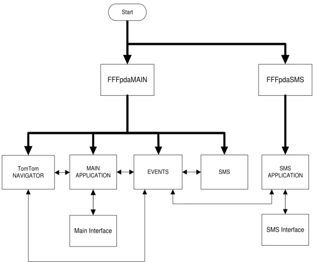
Figure 3.1 – Global system architecture
As Figure 3.1 shows, two applications are deployed on the OS boot-up: FFFpdaMAIN and FFFpdaSMS. FFFpdaMAIN is responsible for the launching of several events: TTN, the auxiliary Events and SMS Threads and its own interface. FFFpdaSMS on the other hand only launches its respective interface.
18
Figure 3.2 – TTN Interface Figure 3.3 – Main Interface Figure 3.4 – SMS Interface
The SMS Thread is constantly checking for incoming or outgoing SMS messages. The appropriate conditioning is done for the messages that are received and passed to the Event thread and also to the messages that the Event thread requests to be sent to the server.
The Events thread as referred on the previous paragraphs is responsible for the Event Processing (incoming), Event Building (outgoing) and TTN Visual event handling. The fundamental interaction with the Main thread is also addressed for logging aspects and also establishing a connection with the other running applications. Finally, this thread also deals with the FFFpdaSMS interface in terms of sending the typed Text and other specific actions that will be explained latter in this chapter.
The Main class can be described as a Global System Manager in terms of its importance on all the events: interconnecting threads through message routing, hardware buttons handling, logging all the events that occurred, system robustness control and also managing its own interface – Figure 3.3.
The FFFpdaSMS Application mainly handles the interface – Figure 3.4 – which consists of an alphanumeric keypad and some Text boxes for visualization purposes.
3.2. Windows Messages
“Unlike MS-DOS-based applications, Windows-based applications are event-driven. They do not make explicit function calls (such as C run-time library calls) to obtain input. Instead, they wait for the system to pass input to them. The system passes all input for an application to the various windows in the application. Each window has a function, called a window procedure that the system calls whenever it has input for the window. The window procedure processes the input and returns control to the system.
19 example, when the user types, moves the mouse, or clicks a control such as a scroll bar. The system also generates messages in response to changes in the system brought about by an application, such as when an application changes the pool of system font resources or resizes one of its windows. An application can generate messages to direct its own windows to perform tasks or to communicate with windows in other applications.
The system sends a message to a window procedure with a set of four parameters: a window handle, a message identifier, and two values called message parameters. The window handle identifies the window for which the message is intended. The system uses it to determine which window procedure should receive the message. A message identifier is a named constant that identifies the purpose of a message. When a window procedure receives a message, it uses a message identifier to determine how to process the message. Message parameters specify data or the location of data used by a window procedure when processing a message. The meaning and value of the message parameters depend on the message. A message parameter can contain an integer, packed bit flags, a pointer to a structure containing additional data, and so on” [MSDN 2008a].
Message Map
“The system sends or posts a system-defined message when it communicates with an application. It uses these messages to control the operations of applications and to provide input and other information for applications to process. An application can also send or post system-defined messages. Applications generally use these messages to control the operation of control windows created by using preregistered window classes” [MSDN 2008a]. On Figure 3.5 all the system-defined messages handled on this system are listed:
Figure 3.5 – System defined messages
ON_WM_CLOSE() ON_WM_DESTROY() ON_WM_CTLCOLOR() ON_WM_SETFOCUS() ON_WM_KILLFOCUS() ON_WM_COPYDATA()
20
On the case of this dissertation, custom application-defined messages were created for the system and its different applications as well as to communicate with other simultaneous processes. The window procedure that receives them must interpret the messages and provide appropriate processing. This type of information transmission method provides the system with a very flexible way of passing data between threads on the same application (ex: Main and Events) and also exchanging data between different applications (Main and SMS).
All systems keep a message queue in order to keep the message flow organized and controlled and with the exception of the WM_PAINT message, the WM_TIMER message, and the WM_QUIT message, the system always posts messages at the end of a message queue. This ensures that a window receives its input messages in the proper first in, first out (FIFO) sequence.
There are two approaches to message processing: PostMessage() and SendMessage(). ”The
SendMessage function sends the message to the window procedure corresponding to the given window. The function waits until the window procedure completes processing and then returns the message result. On the other hand an application can post a message without specifying a window. If the application supplies a NULL window handle when calling PostMessage, the message is posted to the queue associated with the current thread. Because no window handle is specified, the application must process the message in the message loop. This is one way to create a message that applies to the entire application, instead of to a specific window”[MSDN 2008a].
21 Figure 3.6 – Custom application defined messages
The particular data path between intra-thread, inter-thread messages, and also through the applications that each of these messages follows is explained in detail on Chapter 3.3.1.2.
UWM_CENTER UWM_TOFRONT UWM_FKEY UWM_LASTSMS UWM_ADMIN UWM_GLOBALLOG UWM_SMSLOG UWM_NLOG UWM_PRERAWTEXT UWM_RAWTEXT UWM_TEXTTOSEND UWM_SMSTOSEND UWM_GOSMSGO UWM_START UWM_BOOM UWM_SYSTEMBOOM UWM_GOBUILD GSM_OFF GSM_CONNECTING GSM_CONNECTED GSM_NEED_PIN GSM_READY GSM_OPTIONS_OK GSM_PIN_OK UWM_ERROR UWM_READ UWM_SHUTDOWN UWM_PIN UWM_SMSCENTER UWM_SHOW UWM_OPTIONS UWM_LOG
Main application messages
SMS application messages
Data logging messages
Inter-thread routing messages
Events threads messages
22
3.3. MAIN Application
The next chapter explains and describes in detail the actions and procedures of the denominated FFFpdaMAIN application, which specifically translates on all the code developed in the FFFpdaMainDlg, FFFauxiliar and SMS classes. Although all user input is handled through a dialog window programmed on this class, there is a Chapter – 3.6, on which all the interfaces are described.
The first section will deal with the code that was written on the Main Class itself that concerns mainly with initializations and terminations processes, and hardware control handling. It also specifies the windows messages and their routing between applications and threads. The second and last section will describe all the actions performed and handled by the two auxiliary classes: Events and SMS.
3.3.1
Main Class
–
Global Algorithm
The sequence of the algorithm – Algorithm 3.1 – begins with the initialization, where the following actions take place: all hardware Hotkeys are registered; the existence of the text files for the Global and GSM logs, globallog#.txt and gsmlog#.txt is verified. Also both Events and SMS threads are started and the TTN application is launched.
The aspects that deal with robustness, auto-recovery, and self sufficiency are described in greater detail on a latter chapter. It is important to point out that a system crash check is performed at this stage of the process and, if a crash did occur, a response mechanism is initiated. The process begins by sending a SMS text message to the server with the date of the first event received since the PDA was started. This will enable the server to resend all the events from that initial moment till the present, which brings the system up-to-date, and allows for a complete information recovery.
From this stage onwards it is all about runtime operations: hardware control, logging and windows message routing, which will be detailed on the following sub-chapters.
In accordance with the initial system crash check, a proper closing check action is enabled so that the system knows how to proceed on the next startup. Specifically, if the system is correctly terminated a character “1” will be written on the system.txt, else the “0” that was written on the initialization will remain and the recovery process will be called on the next startup.
23 occurrence: unregister the hardware Hotkeys, close the Global and GSM logs text files with the adequate terminator (“end of operation”); close the Events and SMS threads and close the TTN.
Start
End INITIALIZATION
OK systemstate=0 IS systemstate = 0?
SEND SMS TO SERVER
RUNTIME OPERATIONS
PROPER CLOSE?
systemstate=0 TERMINATION
Y
N
Y N
Algorithm 3.1 – Main class global
3.3.1.1 Hardware Control
24
This can be simply translated into the following definition: a key or key combination that causes some function to occur in the computer, no matter what else is currently running [ZDNET 2008a].
According to the Microsoft Development Network™ (MSDN) the process action follows this course when a key is pressed and the system looks for a match against all hot keys. When finding a match, the system posts the WM_HOTKEY message to the message queue of the window with which the hot key is associated. However, in the case that the hot key is not associated with a window, the message is posted to the thread associated with the hot key. This function cannot associate a hot key with a window created by another thread. [MSDN 2008b]
Start
ON_WM_HOTKEY
ON_FKEY
WPARAM = ?
TomTom EVENT SHOW/HIDE APPLICATION
SELECT SCROLL
Algorithm 3.2 – Hardware control
25 Main Application Information Scrolling Keys
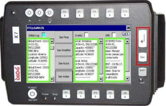
One of the goals of this dissertation was to maximize the user-friendly interaction with the PDA. Taken the fact that the use of gloves is mandatory and the event information flow of data is continuous, the capability of scrolling text is of the upmost importance. So, the use of two hardware buttons on the right side of the PDA was attributed to Upwards and Downwards Scrolling actions – Figure 3.7. This gives a more analog and “in-control” feel. So the only screen touching interaction would be to choose the desired EditBox on which to perform the the action.
Figure 3.7 – Edit boxes scrolling hardware keys
26
Start
WPARAM = 20
smsefocus=TRUE gefocus=TRUE
elfocus=TRUE
End Y
N
N
N
N
Y
Y
Y
Algorithm 3.3 – Scroll UP
Application Selection Keys
The chosen keys were the F1, F3 and F5 as Figure 3.8 illustrates. The remaining adjacent keys, F2 and F4 were disabled for ergonomic and user friendly aspects in order to simplify and focus the firemen‟s range of possibilities.
27 Figure 3.8 – Application selection hardware keys
Start
WPARAM = 8
End Y N
WPARAM = 10
WPARAM = 12
Tomom API CALL
SHOW FFFpda MAIN APPLICATION
SHOW FFFpda SMS APPLICATION Y
Y N
N
28
TomTom™ Events Show/Hide Keys
The importance of intelligible interfaces is of vital importance especially on small screens and in harsh environments scenarios as is the case of this dissertation. However, sometimes visual data overload can occur. The capability to perform correct event filtering may just give the proper visualization needed by the user.
In accordance to those notions the top row of hardware buttons ranging from F6 to F10 – Figure 3.9 – was attributed to Show and Hide actions on the visual representations of the Events. These Events are: Fire, Weather, Vehicle and Water; the Event/key correspondence is detailed on Table 3.1.
Figure 3.9 – TT events Show/Hide hardware keys
Hardware Key Events F6 All Events
F7 Fire
F8 Weather
F9 Vehicle
F10 Water
29 In a similar action with the previous algorithms all the referred events are caught by the ON_FKEY procedure. On this specific case the auxiliary flags allow the system to proceed in terms of the correct action required, to Show or Hide the desired type of event. This algorithm is of similar characteristics on all the keys associated to this type of actions, for illustrations purposes the All Events
action is depicted on Algorithm 3.5.
Start
IS fkey=13?
End
Y
N
HIDE ALL EVENTS IS flagsa=0?
(...)
SHOW ALL EVENTS Y
N
Algorithm 3.5 – TT All Events Show/Hide
3.3.1.2 Message Routing between Threads and Applications
30
3.3.1.2.1 Between Applications
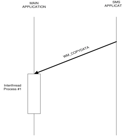
There are many ways to achieve inter-process communication using Visual C++. The main reason is that 32-bit applications run in a separate address space, so the address of a string in one application is not meaningful to another application in a different address space. Using the SendMessage() API function to pass a WM_COPYDATA message overcomes this problem.
1) Send user composed SMS text message
After the user has written the desired text on the SMS application, this text string has to pass it to the main application where it will be rerouted to the SMS thread. This is done by sending a WM_COPYDATA message. The first part is the telephone number of the chosen recipient (Commander, All) and the second part is text message content itself – Figure 3.10.
MAIN APPLICATION
SMS APPLICATION
WM_C OPYD
ATA
Interthread Process #1
31 To keep the user in-loop with human text messages being received by the PDA, the functionality of showing the last received human text message was added to the SMS application. So when this kind of message arrives, the system sends through the Main application a WM_COPYDATA message with the name of the sender and the received text – Figure 3.11.
MAIN APPLICATION
SMS APPLICATION
WM_COPYD ATA Interthread
Process #2
Figure 3.11 – MAIN to SMS message process
3.3.1.2.2 Between Threads
As stated before the need for a FIFO message loop is important to keep the correct chronology of the events Input/Output (I/O) flow. Also the use of the PostMessage() enables the system to continue its actions without runtime interruption. A limitation of Windows messages parameters is that they can only contain integers, but using a pointer to a structure, additional data can be “sent” to other threads. The inter thread messages can be divided in to two different types: General and Logs.
1) General Messages
32
It is important to mention that the Main application will act merely as a router between threads, not producing any data modification. This task is left to the appropriate procedures on the corresponding threads.
Outgoing SMS messages to server
If a SMS text message needs to be sent through a request from the SMS application the text string is passed through a WM_COPYDATA message which now is processed on the Events thread. To pass the information the UWM_TEXTTOSEND message is sent and a specific thread process, BuildEvent(), will construct the message according to the defined SMS protocol. It then send it again to the Main thread through a UWM_SMSTOSEND message. The formatted text will finally be sent to the SMS thread via the UWM_GOSMSGO message which ultimately sends it to the server.
33 Figure 3.12 – Outgoing message processes
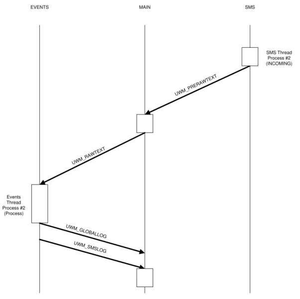
Incoming SMS message from server
When a SMS text message arrives, the SMS thread must pass the raw text to the Main thread through the UWM_PRERAWTEXT message. From this point it is rerouted to the Event thread using the UWM_RAWTEXT message where it will be handled by the ProcessEvent() function.
34
EVENTS MAIN
Events Thread Process #2
(Process)
UWM_ PRER
AWTEXT
SMS
UWM_GLOBAL LOG UWM_SMSL
OG
SMS Thread Process #2 (INCOMING)
UWM_ RAWTEXT
Figure 3.13 – Incoming message processes
System Crash Recovery SMS message
35 Similarly to the processes previously described, a message is sent to the Main thread, UWM_GLOBALLOG, which will log the crash event recovery event – Figure 3.14.
EVENTS MAIN UWM_GLOBAL OG Event Thread Process#1 (Build) UWM_GOSMSG O UWM_ SYST EMBO OM SMS UWM_SMST OSEND SMS Thread Process (OUTGOING) Process#3 (Recovery) Process#2 (Send SMS message)
Figure 3.14 – System crash message process Start Truck position timer and SMS thread
The vehicle where the PDA is mounted must obviously send its own GPS position to the server. However, it should only do that if its position has changed more than a certain amount of degrees every 60 seconds. Therefore, a Truck refresh position timer process must be started at system startup, which is done via the UWM_BOOM message to the Events thread.
36
port, modem communication). This will put the modem on standby ready for any text messaging traffic that will follow – Figure 3.15.
EVENTS MAIN
Event Thread Process#3 (AutoRefresh)
UWM_ BOOM
SMS
SMS Thread Start Process#3
(Initialization)
UWM_ST ART
Figure 3.15 – Start position timer and SMS thread message process
2) Log Messages
This section will address the specific messages (UWM_GLOBALLOG and UWM_GSMLOG) that are sent between the Main and the Events threads, when a logging action is required. The global log entries will be shown on the Global Log EditBox. Both log entries will be written on the respective Text Files (globallog.txt and gsmlog.txt) as evidenced on the following diagrams – Figure 3.16 and Figure 3.17.
37
EVENTS and MAIN MAIN
UWM_ GLOBAL
LOG Process#3 (Log Event)
Write File
Figure 3.16 – Global Log message process
GSM
MAIN SMS
Write File Process#3
(Log Event)
UWM_GSML OG
38
3.3.2
Auxiliar Classes
–
Algorithms
The following classes, SMS and Events, were created and adapted to provide more flexibility to the system, lighten the work load on the Main class and allow a more independent handling process. The only drawback being the information passing between classes had to be done trough the described windows messages with its inherent advantages and disadvantages.
The first class that will be described is the SMS class which deals with all the GSM communication protocol. The second auxiliary class is the Events class which deals with all mechanisms that involve Event reception, processing and construction of the appropriate text messages.
3.3.2.1 GSM Communication
In order for the application to receive the Text Messages from the server a GSM Protocol had to be implemented. This task was greatly facilitated due to the fact that a protocol with a similar configuration was already implemented by NGNS Software Developer Nuno Pinto(SMS Class) which itself uses a Serial Communication Class implemented by Prof. Pedro Vieira. A certain degree of adaptation was imperative in order for these classes to work with the rest of the system, specifically:
- All the Log messages from the Modem, GSM, and Serial classes were sent to the Main Application for the appropriate handling.
- The SIM Card operation of checking for a correct Personal Identification Number (PIN) does not make much sense in the context on which the device will operate.
39 Start INITIALIZATION ConnectGSM Message To Send SEND SMS Y N Y N SENDSMS TIMER READCOM TiMER SMS / REPORT INSERT IN SMS BUFFER SMS REPORT
Text = ? N
Y READ REPORT REMOVE SENT MESSAGE FROM SMS BUFFER
Send Thread Message UWM_PRERAWTEXT
Algorithm 3.6 – GSM communication
The sequence of the algorithm begins with the initialization, where the SMS Center server number is retrieved from a text file, numbers.txt. This text file provides a more flexible and swift manner of changing its value whenever the Administrator desires.
40
timers: SENDSMS Timer and READCOM Timer. These timers have the functions of waiting for a formatted text message to be sent or wait for a new text/report message arrival. Without going into much detail as this class was fully completed and functional, it is important to emphasize a specific point. In order to manage unsent messages that are waiting in queue, an internal thread message loop was used. The removal of sent messages from this loop is done after the reception of the correspondent report has been received.
As a final note it is important to refer that upon a text message arrival the information is passed to the Main class using the windows message UWM_PRERAWTEXT.
3.3.2.2 Event Processing
This sub-chapter has the objective of describing the incoming process of handling the raw SMS Text sent by the FFF Server. The outgoing process of sending all application Text Messages (human or system ones) is described on the previous classes (SMS and Serial).
One of the most important characteristics of this project is the ability to provide access to data from multiple occurrences of five types of Events (Fire, Weather, Auto, Water and Human). The necessity to create five struct types arose in order to provide the Firemen with specific information. This information concerns both geographical visualization, as well as specific event related data, such as: Fire location and status as a Fire event– Figure 3.18; meteorological detailed information and location from a Weather Station, as a Weather event; to Figure – 3.19; vehicle details information and location as an Auto event – Figure 3.20; water supply location and capacity availability as a Water event – Figure 3.21; and finally, human text message details and content as a Human event – Figure 3.22.
Figure 3.18 – Fire event detail
struct AFires
41 Figure 3.19 – Weather event detail
Figure 3.20 – Auto event detail
Figure 3.21 – Water event detail
struct AWaters
EventId Name Time State Longitude Latitude
struct AAutos
EventId IO Name Time Enable AutoType State Longitude Latitude
struct AWeathers
42
Figure 3.22 – Human event detail
To maintain a limited file size and avoid program memory overflow, the dimension of the arrays of structs was limited depending on its specific relevance and recurrence probability. The following Table 3.2 illustrates this fact.
Struct Type Vector Size
Fires 30
Weathers 30
Autos 50
Waters 30
Humans 50
Table 3.2 – Events struct type and array size correspondence
Global Event Process
The sequence of the algorithm – Algorithm 3.7 – begins with the initialization stage, where a series of actions are done. The structs memory allocation is performed with values stated on Table 3.2. The systems own event number (eventnum) is generated. The initial system GPS coordinates are set which are related to the Auto Position Timer handling process. Finally the SMS Server Center number is retrieved from the numbers.txt text file.
The next stage can be described as parallel computing due to the fact that three processes will be running at the same time: Truck Position Refresh, an Incoming event task (SMS text message to send) and an Outgoing event task (SMStext message received). The Truck Position Refresh process is a very simple algorithm. It checks and keeps in memory the vehicles current GPS coordinates every
struct AHumans
EventId IO Name
NameReceiver Time
43 60 seconds and performs a comparison to the previous stored coordinates. If the position of the vehicle has not moved within a radius of one meter, or in angle terms more than 0.000189 degrees in Longitude and 0.000112 degrees in Latitude, the system will not take any action. However if the position has changed a new SMS text message will be sent to the server to inform of the update on the vehicle relative position. Start INITIALIZATION Current values = Past Values SEND New Vehicle Postion
SMS message Y N AUTO REFRESH TIMER CLOSE=True? Start AUTO REFREESH TIMER N Y TERMINATION SMS TEXT MESSAGE TO SEND SMS TEXT MESSAGE RECEIVED End
Algorithm 3.7 – Event class global
44
1) Incoming Event
The incoming event algorithm starts with the Text Message reception process on the SMS thread. This sends the unformatted text to the Events thread through the windows message process previously explained. The raw text must be processed and its events parsed. This action is performed by the ProcessRawText() function which is basically a for loop that calls ProcessEvent() for each event – Algorithm 3.8.
Start
TEXT MESSAGE RECEPTION
PROCESS RAW TEXT
PROCESS EVENT
End
For each Event
Algorithm 3.8 – Incoming event
Process Event
45
Occurance TYPE
REMOVE
UPDATE
End RECURRENT EVENT?
Start
ANALYZE EVENTS
VALID=TRUE?
NEW
Y N
SEND SYSTEM SMS message
Algorithm 3.9 – Process Event
Figure 3.23 – Invalid Water event
This text message is then sent to the server, where the appropriate action will be performed. The next step consists of checking the reoccurrence of the event, so that the system knows what action to take. It can create a NEW event, or on the other hand UPDATE or DELETE an existent one. All the Events types and occurrence actions are shown on Table 3.3.
46
Event/Occurrence NEW UPDATE DELETE
Fires Y Y Y
Weathers Y Y N
Autos Y Y Y
Waters Y Y N
Humans Y N N
Table 3.3 – Event/Occurrence types
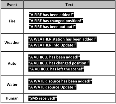
All of these actions are sent to the Main thread for logging purposes. Concerning the TTN a POI type is added with the type of event “Event” and the Event index “#” which translates on the following tag, in the case of a Fire Event:
_Fire 1_
A text message flashes on the navigator screen during five seconds with the following possible formats:
_A “event” has been added !_ _A “event” has been updated !__
_A “event” has been removed!_
47
Event Text
Fire
“A FIRE has been added!”
“A FIRE has changed position!”
“A FIRE has been put out!”
Weather “A WEATHER “A WEATHER station has been added!”
Info Update!”
Auto
“A VEHICLE has been added!”
“A VEHICLE has changed position!”
“A VEHICLE has left the scene!”
Water “A WATER source has been added!”
“A WATER source Update!”
Human “SMS received!”
Table 3.4 – Event/Occurrence TT screen messages
In case the received message is of the Human type the information with the name and text of the sender is displayed on the SMS dialog EditBox on the Main application and sent to the SMS application.
2) Outgoing Event
48
Start
HUMAN TRUCK POSITIONUPDATE
End Type of Event
SYSTEM VALIDITY
SYSTEM CRASH
SEND FORMATED SMS message BUILD EVENT
Algorithm 3.10 – Outgoing Event
Every time the user writes a text message on the SMS application the correspondent windows message process is initiated. Before being sent to the SMS thread, it needs to be formatted by the Build Event() function, to respect the high level developed protocol explained on Chapter 2.3.1.
A Truck Position Update system message after formatting is shown on Figure 3.24:
Figure 3.24 – Track Position Update system message
The System Validity invalid message has already been explained on the previous Process Event paragraph.