Jos´
e Filipe Morgado Vieira
Licenciado em Ciˆencias da Engenharia Electrot´ecnica e de Computadores
A Random Access MAC Protocol for MPR
Satellite Networks
Disserta¸c˜ao apresentada para obten¸c˜ao do Grau de Mestre em Engenharia Electrot´ecnica e de Computadores, pela Universidade Nova
de Lisboa, Faculdade de Ciˆencias e Tecnologia.
Orientadores : Lu´ıs Bernardo, Professor Auxiliar com Agrega¸c˜ao, FCT-UNL
Rui Dinis, Professor Auxiliar com Agrega¸c˜ao, FCT-UNL
J´uri:
Presidente: Prof. Doutor Rodolfo Oliveira
Arguente: Prof. Doutor Francisco Cercas
Vogais: Prof. Doutor Lu´ıs Bernardo
Prof. Doutor Rui Dinis
i
A Random Access MAC Protocol for MPR Satellite Networks
Copyright c Jos´e Filipe Morgado Vieira, Faculdade de Ciˆencias e Tecnologia, Universi-dade Nova de Lisboa
A Faculdade de Ciˆencias e Tecnologia e a Universidade Nova de Lisboa tˆem o direito,
perp´etuo e sem limites geogr´aficos, de arquivar e publicar esta disserta¸c˜ao atrav´es de
exem-plares impressos reproduzidos em papel ou de forma digital, ou por qualquer outro meio
conhecido ou que venha a ser inventado, e de a divulgar atrav´es de reposit´orios cient´ıficos
e de admitir a sua c´opia e distribui¸c˜ao com objectivos educacionais ou de investiga¸c˜ao,
iii
v
To my father, mother, sister, Marisa and to the rest of my family.
”Having a place to go, is a home. Having someone to love, is a family. Having both,
Agradecimentos
Quero come¸car por agradecer ao meu orientador, o Professor Lu´ıs Bernardo. Agrade¸co
bastante o esfor¸co e o apoio que por ele foi feito, ao manter-me sempre motivado,
inte-ressado e claro, toda a ajuda preciosa e grande paciˆencia em todas as fases da elabora¸c˜ao
desta disserta¸c˜ao. Agrade¸co-lhe a verifica¸c˜ao cuidadosa do texto desta disserta¸c˜ao, mesmo
em hor´arios apertados, com correc¸c˜oes e melhoramentos valiosos em todas as sec¸c˜oes. Ao
co-orientador, Rui Diniz pela disponibilidade. Um grande obrigado.
Quero tamb´em para agradecer todo o apoio dado pelos professores da sec¸c˜ao de
teleco-munica¸c˜oes. Ao DEE pelas condi¸c˜oes oferecidas para a realiza¸c˜ao do curso e da disserta¸c˜ao
e tornar este lugar uma autˆetica segunda casa para mim. A todos os docentes que me
acompanharam ao longo destes 5 anos. Foram todos importantes no meu percurso e todos
contribuiram um pouco para a minha forma de encarar a engenharia. `A FCT-UNL por
me acolher e tamb´em por todas as boas condi¸c˜oes oferecidas para a minha forma¸c˜ao e o
bem-estar por todos os dias aqui passados.
Quero tamb´em agradecer `a Professora Helena Fino. Sempre acreditou em mim. Foi
excepcional no apoio, entreajuda, amizade e na orienta¸c˜ao dada `as decis˜oes que tive de
tomar ao longo do curso. A Professora foi determinante para a sua conclus˜ao com sucesso.
Muito obrigado.
Quero agradecer aos meus amigos do gabinetes de telecomunica¸c˜oes por todos os
mo-mentos bem passados e a entreajuda constante que se sentiu nestes locais, de destacar,
F´abio J´ulio, Jo˜ao Chala¸ca, Bruno Branco, Nuno Vasconcelos, Ricardo Lampreia, Pedro
Cunha, V´ıtor Ast´ucia, Pedro Almeida e Francisco Ganh˜ao.
Um grande obrigado ao resto dos meus amigos do curso com os quais estabeleci la¸cos
de amizade que desejo que perdurem ao longo da nossa vida. De destacar, Ruben
Ga-lante, Ant´onio Furtado, F´abio Passos, Telmo Ferraria, Rui Lopes, Francisco Esteves (um
viii
especial obrigado pela revis˜ao da minha disserta¸c˜ao), Gon¸calo Barros, Pedro Leit˜ao, Jo˜ao
”The Champ” Silva, Nuno Pereira, Ana Filipa Sebasti˜ao, Hugo Serra, Ant´onio Eleut´erio,
Jorge ”Abafador” Correia, Filipe Martins e Mauro Dias.
Aos meus amigos fora do curso, estes tamb´em um grande obrigado por acreditarem em
mim, pelo apoio e as devidas desculpas por estes 5 anos, pelo facto de ter praticamente
desaparecido das suas vidas, Tom´as Barros, Duarte Lima Martins, Hugo Tenda, Bruno
Fonseca, Ant´onio Rodrigues, Pedro Bic´o e ao resto da sua fam´ılia, Manuel Cano e ao resto
da sua fam´ılia, Jo˜ao Brissos, Francisco Fialho, Ant´onio Fayad, Carolina Amaral e `a sua
fam´ılia, Isabel Martins e o resto da fam´ılia.
Ao meu Pai e M˜ae, Jos´e e Em´ıdia Vieira e `a minha irm˜a Lena, obrigado por tudo. E
tudo mesmo. S˜ao a luz nos dias escuros, as vozes de for¸ca e os pilares da minha vida para
tudo. Todo o esfor¸co que fizeram para que eu sempre estivesse bem foi essencial, palavras
n˜ao chegam para descrever o qu˜ao importante foram e s˜ao. Obrigado.
Ao resto da minha fam´ılia, Teresa, Ana, Rita, Ant´onio, Manuel, Marina, Francisco e
Maria Jo˜ao um grande obrigado tamb´em pelo apoio dado.
Um par´agrafo especial `a Marisa, que esteve ao meu lado durante este ´ultimos anos,
acreditando sempre em mim, ao longo deste longo percurso. Para al´em de todo o amor e
amizade, foi a minha grande companhia durante o curso e s´o tenho a agradecer por todos
os momentos passados, todo o trabalho conjunto, muito exigente, para obter os melhores
Resumo
Os cen´arios de acesso aleat´orio em redes de sat´elite de baixa altitude (LEO), s˜ao
tipica-mente incompat´ıveis com os requisitos de qualidade de servi¸co (QoS) para tr´afegos
mul-tim´edia, especialmente quando os terminais m´oveis necessitam de operar a baixa potˆencia.
As arquitecturas com optimiza¸c˜ao entre camadas, combinadas com recep¸c˜ao
multipa-cote (MPR), s˜ao uma boa escolha para melhorar o desempenho geral de um sistema sem
fios. O protocolo Hybrid Network-assisted Multiple Access (H-NDMA), exibe elevada
eficiˆencia energ´etica, com capacidade de MPR, mas a sua utiliza¸c˜ao em sat´elites est´a
limi-tada pelo elevado tempo de propaga¸c˜ao. Este protocolo foi adaptado para sat´elites, com
Satellite-NDMA, que requer uma fase pr´evia de agendamento introduzindo um atraso
sig-nificativo.
Nesta disserta¸c˜ao desenvolveu-se um protocolo de acesso aleat´orio que usa H-NDMA,
para redes de sat´elite LEO, denominado Satellite Random-NDMA (SR-NDMA). O
proto-colo foca-se no problema inerente `as redes de sat´elite (tempos de propaga¸c˜ao e consumos
energ´eticos elevados) definindo uma abordagem h´ıbrida com um conjunto inicial de
ac-cessos aleat´orios juntamente com um conjunto de poss´ıveis retransmissi˜oes agendadas.
Um receptor MPR combina as multiplas c´opias recebidas, reduzindo gradualmente a taxa
de erro. S˜ao propostos modelos de desempenho para o d´ebito, atraso, jitter e eficiˆencia
energ´etica considerando filas finitas nos terminais. ´E tamb´em estudado o problema da
optimiza¸c˜ao da eficiˆencia energ´etica do sistema, sendo calculados os paramˆetros que
per-mitem cumprir os requisitos de QoS.
O desempenho do sistema ´e avaliado para um receptor que usa Single-Carrier with
Frequency Domain Equalization (SC-FDE). Os resultados demonstram que o sistema ´e
energ´eticamente eficiente e consegue fornecer um QoS suficiente para suportar servi¸cos
como video conferˆencia.
Palavras Chave: Recep¸c˜ao multi pacote, Satellite Random Network-assisted
Di-versity Multiple Access (SR-NDMA), Acesso aleat´orio, Redes de sat´elite LEO, SC-FDE.
Abstract
Random access approaches for Low Earth Orbit (LEO) satellite networks are usually
in-compatible with the Quality of Service (QoS) requirements of multimedia traffic, especially
when hand-held devices must operate with very low power.
Cross-Layered optimization architectures, combined with Multipacket Reception (MPR)
schemes are a good choice to enhance the overall performance of a wireless system.
Hy-brid Network-assisted Diversity Multiple Access (H-NDMA) protocol, exhibits high energy
efficiency, with MPR capability, but its use with satellites is limited by the high round
trip time. This protocol was adapted to satellites, in Satellite-NDMA, but it required a
pre-reservation mechanism that introduces a significant delay.
This dissertation proposes a random access protocol that uses H-NDMA, for Low Earth
Orbit (LEO) satellite networks, named Satellite Random-NDMA (SR-NDMA). The
pro-tocol addresses the problem inherent to satellite networks (large round trip time and
significant energy consumption) defining a hybrid approach with an initial random access
plus possible additional scheduled retransmissions. An MPR receiver combines the
multi-ple copies received, gradually reducing the error rate. Analytical performance models are
proposed for the throughput, delay, jitter and energy efficiency considering finite queues
at the terminals. It is also addressed the energy efficiency optimization, where the system
parameters are calculated to guarantee the QoS requirements.
The proposed system’s performance is evaluated for a Single-Carrier with Frequency
Domain Equalization (SC-FDE) receiver. Results show that the proposed system is energy
efficient and can provide enough QoS to support services such as video telephony.
Keywords: Multipacket Reception, Satellite Random Network-assisted Diversity
Multiple Access (SR-NDMA), Random Access, LEO Satellite Networks, SC-FDE.
Acronyms
ARQ Automatic Repeat-reQuest BER Bit Error Rate
BS Base Station CC Code Combining
CDMA Code Division Multiple Access CDPD Cellular digital packet data
DAMA Demand Assigned Multiple Access DC Diversity Combining
DTMC Discrete Time Markov Chain EPUP Energy Per Useful Packet FDE Frequency Domain Equalization FDM Frequency Division Multiplexing FF-NDMA Feedback Free-NDMA
FDMA Frequency Division Multiple Access FEC Forward Error Correction
FFT Fast Fourier Transform GPS Global Positioning System GSO GeoStationary Orbit
H-ARQ Hybrid Automatic Repeat-reQuest
H-ND MA Hybrid Network-assisted Diversity Multiple Access HIPERLAN High Performance Radio LAN
HSDPA High-Speed Downlink Packet Access HSUPA High-Speed Uplink Packet Access
xiv ACRONYMS
IC Interference Cancelation ID Identification
IFFT Inverse Fast Fourier Transform ISI Intersymbol Interference
ISL Inter Satellite Link LAN Local Area Network LEO Low Earth Orbit LTE Long Term Evolution MAC Medium Access Control MEO Medium Earth Orbit
MIMO Multiple Input Multiple Output MMSE Minimum Mean Squared Error
MLSE Maximum Likelihood Sequence Estimation MPR MultiPacket Reception
MT Mobile Terminal MUD Multi-User Detection
NDMA Network-assisted Diversity Multiple Access NGSO NonGeoStationary Orbit
OBP OnBoard Processing
OFDM Orthogonal Frequency-Division Multiplexing OSI Open Systems Interconnection
PAR Peak-to-Average Ratio
PAPR Peak-to-Average Power Ratio PER Packet Error Rate
PIC Parallel Interference Cancelation PHY Physical
PSK Phase-Shift keying
xv
QPSK Quadrature Phase-Shift Keying RA Random Access
RTT Round-Trip Time
S-NDMA Satellite Network-assisted Diversity Multiple Access SA Scheduled Access
SC Single Carrier
SC-FDE Single Carrier-Frequency Domain Equalization SIC Successive Interference Cancelation
SR-NDMA Satellite Random Network-assisted Diversity Multiple Access TDMA Time Division Multiple Access
Contents
Agradecimentos vii
Resumo ix
Abstract xi
Acronyms xiii
1 Introduction 1
1.1 Current context . . . 1
1.2 Objectives and Contributions . . . 2
1.3 Dissertation Structure . . . 3
2 Literature Review 5 2.1 Satellite Communications . . . 5
2.1.1 Satellite Constellations . . . 6
2.1.2 Systems in Low Earth Orbit . . . 7
2.1.2.1 Iridium Satellite System . . . 8
2.2 Satellite Multiple Access Schemes . . . 9
2.2.1 Code Division Multiple Access . . . 10
2.2.2 Frequency Division Multiple Access . . . 11
2.2.2.1 Orthogonal Frequency Division Multiplexing . . . 11
2.2.2.2 Single Carrier with Frequency Division Equalizer . . . 13
2.3 Error Correction Schemes . . . 14
2.3.1 Forward Error Correction . . . 15
2.3.2 Diversity Techniques . . . 15
2.3.3 ARQ Schemes . . . 16
2.3.4 Hybrid ARQ Schemes . . . 16
2.3.4.1 Type-I Hybrid ARQ Schemes . . . 17
2.3.4.2 Type-II Hybrid ARQ Schemes . . . 18
2.4 MAC Protocols in Satellite Communications . . . 19
2.4.1 Random Access Protocols . . . 20
2.4.2 Demand Assignment Protocols . . . 22
xviii CONTENTS
2.5 Collision Resolution Techniques . . . 22
2.5.1 PHY-Layer Solutions . . . 23
2.5.1.1 Multipacket Reception . . . 23
2.5.2 PHY-MAC Cross-Layered Designs . . . 26
2.5.2.1 Network-assisted Diversity Multiple Access Protocols . . . 27
3 Satellite-Random-NDMA Protocol 33 3.1 System Characterization . . . 33
3.1.1 Medium Access Control Protocol . . . 34
3.1.1.1 Random Access Mode . . . 35
3.1.1.2 Scheduled Access Mode . . . 36
3.1.1.3 Operation of the SR-NDMA protocol . . . 38
3.1.2 Multipacket Reception - Receiver Structure . . . 39
3.2 Analytical Performance Model . . . 42
3.2.1 Scheduled Access Phase . . . 43
3.2.2 System’s Steady State . . . 46
3.2.3 Throughput and Channel Utilization Analysis . . . 49
3.2.4 Energy Consumption . . . 50
3.2.5 Delay and Jitter Analysis . . . 51
3.2.5.1 Initial Time . . . 51
3.2.5.2 Queuing delay until RA transmission . . . 52
3.2.5.3 Service Time . . . 52
3.2.5.4 Total delay and jitter . . . 54
3.3 Optimization Procedure . . . 55
4 Simulation Results 57 4.1 System Considerations . . . 57
4.1.1 Satellite orbits and system’s Round Trip Time . . . 57
4.1.2 Handling very low power using CDMA . . . 58
4.1.3 Transmission and System Parameters . . . 60
4.2 Performance Analysis . . . 63
4.2.1 n⋆ calculation . . . 63
4.2.2 Bmax parameter . . . 65
4.2.3 N parameter . . . 66
4.2.4 n(0P) parameter . . . 70
4.2.5 S-NDMA and SR-NDMA comparison . . . 72
5 Conclusions 75 5.1 Final Considerations . . . 75
5.2 Future Work . . . 76
CONTENTS xix
Appendix 87
List of Figures
2.1 LEO-Low earth orbit. Adapted from [Ipp08] . . . 8 2.2 Generic architecture of the Iridium system and its typical services. Adapted
from [JT01] . . . 9 2.3 OFDM - signal processing. Adapted from [FABSE02] . . . 12 2.4 SC-FDE - signal processing. Adapted from [FABSE02] . . . 14 2.5 Classification of techniques applied for MPR. Adapted from [LSW12] . . . 24 2.6 A cross-layer design on the basis of multiple packet reception. Adapted
from [LWLK07] . . . 26 2.7 S-NDMA Demand Assigned scheme. Adapted from [GBD+12] . . . 31
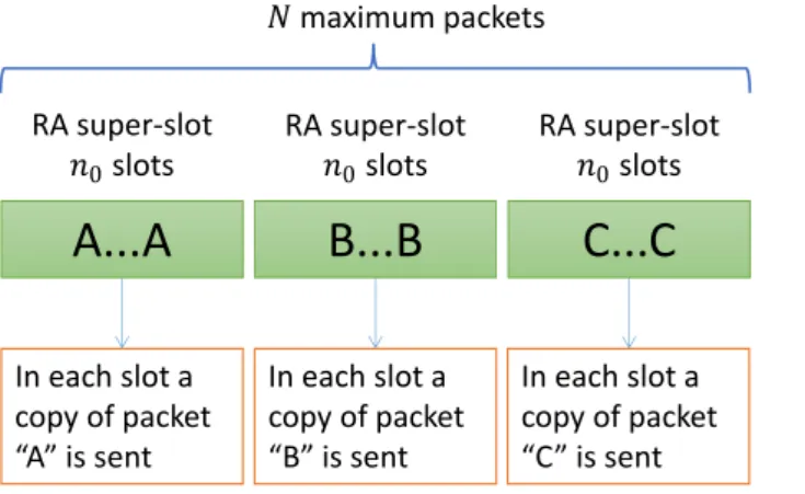
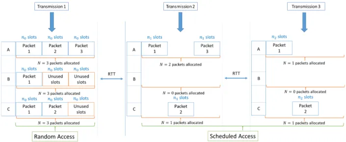
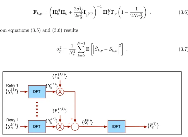
3.1 Maximum allocated RA slots and the structure of each RA super-slot . . . 35 3.2 Two MTs sending a packet using SR-NDMA . . . 37 3.3 P = 3 users transmitting MAC data packets using SR-SNDMA . . . 38 3.4 Structure of the receiver for the l packet reception . . . 41 3.5 BER performance for the adopted receiver. Adapted from [GDB+11] . . . . 42 3.6 The time a MT has to wait in average to start its transmission. . . 51 3.7 Random access, l= 0. The time a packet spends on queue depends onN. . 52 3.8 Scheduled access, l= 1...R. The time the remaining packets last in queue
depend mainly onBmax and the optimization procedure for scheduling the
slots. . . 53
4.1 Satellite’s covering angle range . . . 57 4.2 Satellite with θ displacement for RTT calculation purposes . . . 58 4.3 The system’s data structure . . . 59 4.4 ζRminimum that satisfies PER ≤1% over Eb/N0 . . . 64
4.5 Optimal n(0P) values over minimum Eb/N0 . . . 64
4.6 ρb (Channel utilization) over the allocated slots Bmax. - 4.6(a) various N
-4.6(b) various Eb/N0 . . . 65
4.7 ρb (Channel utilization) over the allocated slotsBmax. - 4.7(a) variousn(0P)
- 4.7(b) various λJ . . . 66 4.8 Throughput over the total load λJ for different values of N, Bmax = 32
slots, optimaln(0P) for 5 MTs . . . 67
xxii LIST OF FIGURES
4.9 Throughput over the Total Load for different values ofN,Bmax= 16 slots,
optimaln(0P) for 5 MTs . . . 67 4.10 Delay and Jitter over the total loadλJ for different values ofN . . . 68 4.11 EPUP over the Total Load for different values of N, Bmax = 32 slots,
optimaln(0P) for 5 MTs . . . 69 4.12 EPUP over the total allocated slots per RTT (Bmax slots) different values
of N, optimaln(0P) for 1 MT,lambdaJ =0.13 . . . 69 4.13 First example of EPUP and delay over the throughput for differentn(0P) . . 70 4.14 Second example of EPUP and delay over the throughput for different
opti-mal n(0P) . . . 71 4.15 EPUP over the total allocated slots per RTT (Bmax slots) for different
optimaln(0P),N=4, λJ =0.13 . . . 72 4.16 EPUP comparison between S-NDMA and SR-NDMA when 5 MTs transmit,
List of Symbols
B Bandwidth used in the uplink in Hz . . . 61
BmaxMaximum number of slots allocated by the satellite to a MT per RTT . .39
c Speed of light in m/s . . . 58
DmaxMaximum delay bound . . . 55
E Expected value of a random variable . . . 45
Eb Average bit energy associated to a given packet transmission . . . 15
Ep Packet transmission energy . . . 51
fb Binomial distribution . . . 48
fc Carrier frequency . . . 60
Fk,p Feed-forward coefficients of the linear receiver . . . 40
Gr Antenna gain at the satellite in dBs . . . 60
Gt Antenna gain at the mobile terminal in dBs . . . 60
Hk,p(r) Channel frequency response from thepth user, during therth transmission 40
J Number of members of a group of MTs associated with a satellite . . . 35
Kk(l) One number of MTs that successfully transmit at retransmission k during an SR-NDMA epoch with lretransmission super-slots . . . 44
xxiv LIST OF SYMBOLS
l lth transmission in an epoch . . . 36
Lf s Free space path loss in dBs . . . 60
M Number of bits in a data packet . . . .41
N Maximum number of packets that a MT can send per epoch . . . 35
M AX Maximum MT’s in queue length . . . 47
N0 Power spectral density of the noise . . . 15
n Matrix that includes the number of slots used for all retransmissions and different MTs . . . 36
nP
l Number of slots used with P MTs for the l transmission . . . 36
n(P) Vector containing the slots withP MTs for all transmissions . . . 36
n0 Number of random access slots used in the initial transmission . . . 35
n(0P) Optimal number of random access slots, forP MTs . . . 64
Ns Number of symbols in a data block . . . 39
Nk(r) The channel noise during therth transmission . . . 40
n(P) Matrix containing all slots values, for all possible retransmissions, to be used for all possibleP MTs . . . 36
P Number of transmitting users . . . 36
Pp The transmission power per packet . . . 50
Pr Received power at the satellite in dBs . . . 60
pt Transmission signal power in watts . . . 60
Ptx
The probability of a MT transmitting a packet in one of the N sets of n0
xxv
qm
Number of packets in the MT’s queue in the beginning of the m group of RA slots . . . 47
QmaxMaximum capacity of the queue . . . 47
Qx Gaussian error function . . . 41
R Scheduled retransmissions . . . 35
Re Earth’s radius . . . 58
rs Distance from a MT to the satellite in km . . . 58
S Throughput . . . 49
ST Service Time . . . .54
Sf CDMA spreading factor . . . .59
Sk,p Data block transmitted by a user p, in the frequency domain . . . 39
sn,p Data block transmitted by a user p, in the time domain . . . 39
T Round Trip Time in slots . . . 35
Ton Slot transmission time . . . 50
Vl Number of packets successfully received during the lth SA retransmission
slots . . . 48
Xl Number of packets being transmitted inlth SA retransmission slots . . . 47
X0 Number of packets being transmitted in the RA slots . . . 47
Yk,r
Received signal, from multiple MTs, at the receiver in the frequency domain for a given transmission r . . . 39
α Peak-to-Average-Ratio of the radio frequency power amplifier . . . 50
η Drain efficiency of the radio frequency power amplifier . . . 50
xxvi LIST OF SYMBOLS
Ψ(P,R)Random state vector that defines the packet transmission behavior . . . . 44
ψl(P,l)
The random state vector with the number of MTs that successfully transmit at retransmissionkduring an SR-NDMA epoch withlretransmission super-slots . . . 44
Ω(Pl) The space state defined by the SR-NDMA epoch withlretransmission super-slots andP MTs . . . 44
ρR RA slot utilization . . . 47
ρb Allocated bandwidth efficiency . . . 49
ξ Steady state queue distribution . . . 47
τ MTs total delay . . . 37
θ Satellite’s covering angle . . . 57
̟ The time in queue until a packet is transmitted at the RA slots . . . 52
ǫ Packet loss ratio . . . 57
ζl(P) Total number of slots for P users until the lth transmission . . . 40
ε Total packet loss ratio . . . 49
Chapter 1
Introduction
1.1
Current context
An important requirement in the evolution of telecommunications is its capability to
pro-vide permanent and ubiquitous connectivity regardless of the location. The integration of
the satellite communications in the terrestrial network will bring the telecommunications
network to a level where global connectivity, anywhere and any time, can be achieved. The
ubiquitous coverage of the satellite network provides a complementary service to the very
high data rate available in the areas covered by terrestrial cellular services. For example,
it will be possible a reachability on inaccessible areas, or areas involved in unpredictable
catastrophic events where the infrastructure was destroyed.
With the advent of 4G Long Term Evolution (LTE)-Advanced, mobile ultra-broadband
Internet access for Mobile Terminals (MTs) enabled services that rely heavily on
broad-band and Quality of Service (QoS), such as high-definition mobile TV, gaming services, IP
telephony, mobile web access, video conferencing and cloud computing. To truly
appreci-ate the user’s experience anywhere in the world, it makes sense to integrappreci-ate the terrestrial
network with a satellite network. However, compared to terrestrial cellular infrastructures,
satellite networks have higher propagation delays and require much higher transmission
power due to the large distance between the terminal and the satellite. Therefore, to
seamlessly integrate the 4G LTE terrestrial network with satellite networks, and at the
same time provide multimedia services with guaranteed QoS, MTs must have low cost
and operate with low power. Future technology will have energy efficiency as a major
2 CHAPTER 1. INTRODUCTION
requirement for such systems and it should be fully compliant with the users demands.
1.2
Objectives and Contributions
Most of the medium access control (MAC) protocols proposed for satellite networks that
satisfy QoS requirements [Pey99], [DGDRH09] use Demand Assigned Multiple Access
(DAMA) or a hybrid mode with random access and reservations mechanisms. However,
these options lead to an overhead increase and higher delay, due to reservations
mecha-nisms in DAMA, or result in the loss of some packets due to collisions during the random
access phase.
Multipacket Reception (MPR) and cross-layered techniques are a good solution to
en-hance the communication in wireless mediums, but with the cost of higher receiver and/or
MAC protocol complexity. Network Diversity Multiple Access (NDMA) [TZB00] is a
cross-layer solution that uses MPR, which was proposed for terrestrial cellular networks,
where the Base Station (BS) forces the transmission of a number of MAC packet copies
equal to the number of MTs involved in a collision. An evolution of NDMA was
pro-posed in [GPB+11], called Hybrid-NDMA (H-NDMA), which applied Hybrid Automatic
Repeat reQuest (H-ARQ) to NDMA in a terrestrial cellular network, forcing additional
transmissions to enhance packet reception when difficult reception conditions persist, e.g.
low Signal-to-Noise Ration (SNR) or high interference. However, H-NDMA is unsuitable
for satellite networks due to the multiple control packets required for additional
retrans-missions and acknowledgements, which may introduce delay and jitter incompatible with
several kinds of QoS requirements [AMCV06]. In order to overcome these issues, Satellite
NDMA (S-NDMA) [GBD+12] was proposed, which applied the H-NDMA approach in
a satellite network, considering a Demand Assigned Multiple Access (DAMA) approach.
The satellite schedules multiple concurrent MTs, packet transmissions, defining the
trans-mission power that minimizes the MTs average energy consumed for each packet correctly
received. However, the DAMA approach introduces an initial extra Round-Trip Time
(RTT) delay for slot reservation. This dissertation proposes the Satellite Random-Access
NDMA (SR-NDMA) protocol, which adds the random-access capability to S-NDMA. It
combines random access and scheduled access slots, and lets MTs transmit without
1.3. DISSERTATION STRUCTURE 3
(LEO) satellite network, based on the Iridium satellite constellation, using Single
Carrier-Frequency Domain Equalization (SC-FDE) scheme for the uplink transmission. Analytical
performance models are proposed to compute the throughput, energy consumption, delay
and jitter, considering a constrained bandwidth and limited queue size restrictions, and
assuming homogeneous Poisson load. This model is used to calculate the optimal energy
transmission parameters that guarantees the QoS requirements, given a know uniform
average load.
In result of the work developed in this dissertation, a paper was accepted in the
IC-CCN 2013 conference, [VGB+13], and another paper was submitted to the New2An 2013
conference. A journal article is also being prepared using the work developed.
1.3
Dissertation Structure
The dissertation structure is briefly organized as follows: Chapter 2 contains a related work
overview. A brief overview about satellite networks is followed by the typical modulation
schemes used, error control mechanisms, typical MAC protocols for satellite networks and
finalizes with the presentation of collision resolution methods, which include an overview
about MPR and NDMA. Chapter 3 presents the SR-NDMA protocol proposed, covering
the system overview, the MAC protocol and the analytical performance models, which
describe the system and the optimization approach followed to calculate its configuration.
Chapter 4 presents the SR-NDMA system configuration parameters considered and a set of
performance results, i.e. throughput, energy consumption and transmission delay. Finally,
Chapter 5 contains the conclusions and incorporates future work that could be done by
Chapter 2
Literature Review
2.1
Satellite Communications
Satellite networks have properties which make them attractive for a variety of applications
and a set of situations where they are the only resource to communicate. For instance,
satellites have a coverage area that greatly exceeds that of a terrestrial system, they allow
the use of higher bandwidths and support on a global basis all forms of communications,
ranging from simple point-of-sale validation to bandwidth intensive multimedia
applica-tions [IRS+04].
Satellites traditionally serve as bent pipes, i.e. a satellite is constituted by several
transponders, each of which is listening to a portion of the radio-frequency spectrum. Each
transponder amplifies the incoming signal and rebroadcasts it into another frequency to
avoid interference with the incoming signal. As bent pipes, they act as repeaters between
two communication points on the ground, so there is no OnBoard Processing (OBP)[HL01].
However, some of the satellite systems do allow OBP. This can be advantageous in a
com-munication satellite by providing baseband processing and switching; i.e. its functions are
similar to those performed in terrestrial local area networks, which include, demodulation,
demultiplexing, error detection and correction, switching, congestion control, buffering,
remultiplexing, modulation and network synchronization [Ins00, p. 39].
We are faced with the challenge of integrating the terrestrial and satellite systems.
With the forthcoming appearance of the fourth generation of wireless communication
sys-tems, future satellite systems should support applications with stringent Quality of Service
6 CHAPTER 2. LITERATURE REVIEW
(QoS) and demanding bit-rates [IRS+04].
The current satellite environment is quite rigid [LK07]. In the first place, the cost
associated with designing, developing and operating a space vehicle is extremely high.
Secondly, the requirements are stringent because satellites have to survive in a harsh
en-vironment without the easy access for repairs, maintenance or upgrades. This leads to
developers having the obligation to build inflexible specialized vehicles with long life
ex-pectancy. In [LK07] a study was made with the purpose to change the mindset of the
future satellite system to a more flexible one, showing that a long term benefit can be
obtained. For example, to improve flexibility, a software update can be sent on an
up-link to easily adapt the function of the satellite. Another example is shared processing
in a satellite network; as processing capability improves, all satellites utilizing the shared
processor would be able to take advantage of the performance improvement [KB00].
2.1.1 Satellite Constellations
A satellite system can be classified into Geostationary Orbit(GSO) and Nongeostationary
orbit(NGSO), which includes Medium Earth Orbit(MEO) and Low Earth Orbit (LEO)
[PD11, p. 117]. The GSO orbit contains the majority of the satellites in operation. These
satellites are synchronized with the Earth’s rotation, appearing fixed to an observer on
Earth. Along with its high altitude, 35,786 km above the equator, a GSO satellite can
cover one third of the Earth’s surface, meaning three GSO satellites are enough for a global
coverage. In spite of this, the cost associated with the launching of GSO satellites is high,
and there is a inherent signal degradation with distance, due to its high altitude [HL01].
These disadvantages force the use of large antennas and large transmission power for both
the satellites and the ground terminals. Adding to this, there is a high propagation delay
for these links (typical value of 250 ms), which does not help for real-time traffic [Uni02,
p. 356].
The NGSO satellites systems have the unique feature of viewing the entire Earth’s
surface periodically from a single satellite. If simultaneous viewing of the Earth is
re-quired, a constellation of satellites can be employed [Uni02, p. 419].
The LEO satellites systems (with orbits ranging from 160 to 1500 km above the
2.1. SATELLITE COMMUNICATIONS 7
high speed data and voice communications. In contrast to GSO systems, due to their
rapid motion, which causes more frequent handovers [CAI06], LEO orbits require more
satellites to provide the same communications services. However, they are much smaller
and require significantly less energy to insert into orbit [Ipp08, p. 28]. Due to the shorter
path distances to the ground stations, the LEO orbits require smaller power and smaller
antennas sizes of the earth terminals and have lower propagation delays, between 10 and
25 ms [JT01]. The LEO satellites can also, with proper inclinations, cover high latitude
locations, including polar areas, which cannot be reached by GSO satellites [Ipp08, p. 27].
The MEO satellites orbit at an altitude between 2000 and 4000 km [BWZ00], hence
the MEO satellites cover larger areas of the Earth surface, are visible for longer
peri-ods and a lower number of such satellites is necessary to cover the entire Earth [PP07],
compared to LEO satellites. The MEO orbit is very similar to LEO’s but has higher
prop-agation delays, on the order of 80 ms [BWZ00]. MEO satellites have been found useful
for meteorological, remote sensing, navigation and position determination applications.
The Global Positioning System (GPS), for example, employs a constellation of up to 24
satellites operating in 12-hour circular orbits [Ipp08, p. 28].
2.1.2 Systems in Low Earth Orbit
LEO satellite constellations (Figure 2.1) are promising solutions for satellite networks,
due to their low delay and bit error characteristics [NBSL11]. Although, since they do
not have a high view angle to offer adequate global coverage, these systems require a large
number of satellites (24 to 66 have been proposed). These satellites must be served by a
large number of earth stations, perhaps 200 or more. Low altitude may also increase the
risk of shadowing1 of the signal by vegetation, terrain and buildings. As with the cellular
service, this may cause interruptions in transmissions [Man95].
LEO networks can be separated according to the kind of applications they offer. They
can be separated into Low Bit Data Rate (Little LEO), Mobile Telephony (Big LEO) and
High Bit Data Rate (Broadband LEO). A LEO system which provides Low Bit Data Rate
is ORBCOMM. Example of Big LEOs are Iridium and Globalstar, while for Broadband
LEO systems there are Teledesic and Skybridge [Man95] [Uni02, p. 420].
8 CHAPTER 2. LITERATURE REVIEW
160 - 1500 km circular orbits
–– requires earth terminal tracking
–– approx. 8 to 10 minutes per pass for an earth terminal
–– requires multiple satellites (12, 24, 66, . . . ) for global coverage –– popular for mobile satellite communications applications
160 – 1500 km circular orbits
Figure 2.1: LEO-Low earth orbit. Adapted from [Ipp08]
Iridium and Globalstar provide narrow-band mobile voice services, whereas Teledesic
and Skybridge provide primarily fixed broadband connections comparable to urban
wire-line service. ORBCOMM is used for commercial purposes primarily to provide electronic
mail and paging to portable and mobile devices. It is not intended to carry voice calls
[Man95].
2.1.2.1 Iridium Satellite System
Iridium system was completely deployed in May of 1998. It is based on a constellation
proposed by [AR87], with 66 cross-linked operational satellites, plus seven in-orbit spares.
These 66 satellites are arranged in six north-south necklaces, with one satellite every 32
degrees of latitude. All the satellites belonging to this constellation are located 780 km
above the Earths surface [PRFT99].
Satellites that are part of Iridium system use Inter-Satellite Links (ISLs) to route
traf-fic. Call setup procedures and the interface of Iridium with the existing Public Switching
Telephone Network (PSTN) are handled by regional gateways. Iridium provides a
net-work where the satellites communicate with other satellites that are near and in adjacent
orbits. This kind of operation allows a simple call to roam over several satellites, coming
back to the ground when downlinked at an Iridium gateway, and patched into an PSTN
for subsequent transmission to destination. The existence of 48 cells (spot beams) per
satellite with a capacity of 3840 channels, with 402Km of diameter apiece on the Earths
surface for each satellite, is important to decrease the probability of existing dropped calls
2.2. SATELLITE MULTIPLE ACCESS SCHEMES 9
while others are used for data and voice [PRFT99].
The ISLs and the links to the ground gateway stations work in the Ka band2. The
frequency band used for mobile, pager and navigation services is the L band3, which use
the band 1.61 to 1.63 GHz [BWZ00]. Figure 2.2 shows the Iridum system architecture
with its typical services.
Iridium satellites are also programmable, so it is possible to upload new instructions
to them, in order to maintain good performances and high reliability levels [www12].
Figure 2.2: Generic architecture of the Iridium system and its typical services. Adapted from [JT01]
.
2.2
Satellite Multiple Access Schemes
In satellite systems, there exist several ways to define separate communication channels,
shared by several terminals [Ret80] [Uni02, p. 287]: Frequency Division Multiple
Ac-cess (FDMA), Time Division Multiple AcAc-cess (TDMA), Code Division Multiple AcAc-cess
(CDMA) and Space Division Multiple Access (SDMA), which are a set of common
ac-cess techniques. More recently, in order to support higher data rates and to be able
to cope with severe multipath propagation 4 two additional solutions were adopted in
the WiMax/3GPP-LTE systems: Orthogonal Frequency Division Multiplexing (OFDM)
2frequency band ranging from 18 to 31 GHz 3L band ranges typically from 1Ghz to 2Ghz
10 CHAPTER 2. LITERATURE REVIEW
and Single-Carrier Frequency-Domain-Equalization (SC-FDE) [Wan11]. In this section, a
short overview is given to CDMA, OFDM and SC-FDE since they are considered in the
work developed in this dissertation.
2.2.1 Code Division Multiple Access
CDMA is a form of spread spectrum communication in which a narrowband signal is
deliberately spread in the frequency domain, resulting in a signal with a wider bandwidth.
This can make it more tolerant to interference, noise and jamming as well as allowing
multiple signals from different users to share the same frequency band [PD11, p. 135].
The last characteristic is feasible since CDMA employs a special coding scheme that allows
multiple users to be multiplexed over the same physical channel. The transmissions are
distinguished by using different codes for each user, which are approximately orthogonal.
That code allows CDMA on the receiver side to reject everything except the desired
signal, using a frequency correlation operation. The receiver has the obligation to know
the codeword that the transmitter used, in order to detect the message signal. There is
no knowledge among users, so it means that each users operates in a independent way
[Rap01, p. 405].
CDMA is practical for digital formatted data and offers the highest power and spectral
efficiency operation of the three fundamental techniques (FDMA,TDMA,CDMA). A good
spectral efficiency is achieved since several CDMA networks can share the same frequency
band, because the undetected signal behaves as noise to all receivers without knowledge
of the code sequence. This is particularity useful in applications such as NGSO Mobile
Satellite Service systems, where bandwidth allocations are limited. Also, only a small
portion of the signal energy is present in a given frequency band segment at any time,
therefore, frequency selective fading or dispersion will have a limited effect on overall link
performance. Again, because only a small portion of the signal energy is present in a
given frequency band segment at any time, the signal is more resistant to intentional or
unintentional signals present in the frequency band, thereby reducing the effects on link
performance [Ipp08, p. 285].
However, CDMA can have performance issues due to the near-far problem. This occurs
2.2. SATELLITE MULTIPLE ACCESS SCHEMES 11
Stronger signals, raise the noise level for weaker signals at the receiver, making them less
likely to being detected. The near-far problem is particularly difficult in CDMA systems,
where transmitters share transmission frequencies and transmission time. To combat the
near-far problem, power control is used in most CDMA implementations. Power control
is provided by each base station in a cellular system and assures that each terminal in
the base station coverage area provides the same signal level to the base station receiver.
This solves the problem of a nearby subscriber overpowering the base station receiver and
drowning out the signals of far away subscribers. Despite the use of power control within
each cell, terminals out of the cell provide interference which is not under the control of
the receiving base station [Rap01, p. 406].
2.2.2 Frequency Division Multiple Access
FDMA is a channel access method based on the Frequency Division Multiplex (FDM)
scheme, which associates different frequency bands to different data streams. In the
FDMA case, the data streams are allocated to different users. As a result, each user
is individually allocated to one or several frequency bands (or channels) [PD11, p. 133].
For a large bandwidth, FDMA has some limitations due to equalization complexity.
Equalization has the purpose of reducing Intersymbol Interference (ISI) to allow the
re-covery of the transmitted symbols. FDMA was improved by two additional approaches,
OFDM and SC-FDE.
2.2.2.1 Orthogonal Frequency Division Multiplexing
OFDM is an evolution of FDM, and works by transmitting several modulated sub-carriers
in parallel where each one occupies a narrow bandwidth [Cim85]. This way, the channel
bandwidth is divided into many sub-carriers that independently send data. Each
subcar-rier is modulated with a conventional modulation scheme such as Quadrature Amplitude
Modulation (QAM) or Phase-Shift Keying (PSK) at a lower symbol rate than the original
data stream, maintaining total data rates similar to conventional single-carrier modulation
schemes in the same bandwidth [NP00, p. 33].
OFDM, as opposed to single-carrier schemes, has the ability to handle severe channel
conditions such as frequency-selective fading due to multipath or narrowband interference,
ampli-12 CHAPTER 2. LITERATURE REVIEW
tude and phase of each subcarrier, equalizing each sub-carriers gain and phase does the
compensation for frequency-selective fading [FABSE02]. The equalization is less complex
because the many narrowband signals are modulated at a low symbol rate instead of one
rapidly modulated wideband signal. Multipath propagation, which can cause ISI, can
be eliminated by introducing a guard interval between each symbol. The feasibility of
introducing guard intervals is bigger in OFDM since low symbol rates make longer
sym-bol durations, as long as the channel dispersion is not longer than the guard interval, so
the use of time domain equalization is not usually mandated. However, in case of higher
data rates and channels with extensive time dispersion an equalizer is unavoidable [BS04,
p. 103].
IFFT CPI Channel FFT ChannelInvert Detect
Receiver Transmitter
OFDM
CPI:Cyclic prefix insertion
Figure 2.3: OFDM - signal processing. Adapted from [FABSE02] .
In OFDM (Figure 2.3), Inverse Fast Fourier Transform (IFFT) is applied on blocks
of M data symbols at the transmitter side to generate the multiple sub-carriers. On the other hand, the receiver can extract the sub-carriers by applying a Fast Fourier Transform
(FFT) on received blocks [FABSE02]. There is also a cyclic prefix whose goal, besides
helping in avoiding ISI with the previous data block, is to make the received block look
periodic, simulating a circular convolution, allowing an efficient FFT operation. Cyclic
prefix carries the repetition of the last data symbol in a block, being consequently
dis-carded at the receiver [BS04, p. 27].
It is widely recognized that a serious problem in OFDM is the possibility of extreme
amplitude excursions of the signal. The signal is the sum of the several slowly modulated
sub-carriers. In the most cases, the different carriers line up in phase at some instant in
time, and therefore produce a very high Peak to Average Power Ratio (PAPR). The
2.2. SATELLITE MULTIPLE ACCESS SCHEMES 13
transmit these peaks, not only must the D/A (Digital-to-Analog) converter have enough
bits to accommodate the peaks, but more importantly, the power amplifier must remain
linear over an amplitude range that includes the peak amplitudes. This leads to both high
cost and high power consumption [BS04, p. 57]. The multiple access is achieved in OFDM
by assigning subsets of sub-carriers to individual users. This allows simultaneous low data
rate transmission from several users.
As a proof of its maturity, OFDM was selected as the High Performance Local Area
Networks (HIPERLAN) transmission technique, became part of the IEEE 802.11 (Wi-Fi)
standard as well as one of the the radio technologies for the LTE-Advanced.
2.2.2.2 Single Carrier with Frequency Division Equalizer
SC-FDE is an alternative to OFDM. While OFDM is a recognized multi-carrier solution to
combat the effects of multipath conditions, mainly due to the favorable trade-off it offers
between performance in severe multipath conditions and the signal processing complexity
[Cim85], single-carrier modulation when combined with frequency domain equalization
(SC-FDE) is capable of delivering a similar performance with essentially the same overall
complexity [FABSE02], plus some advantages characteristic to single-carrier schemes.
SC-FDE has data sent at a high rate through one carrier and the data is modulated,
for example with QAM or PSK, with equalization at the frequency domain. The frequency
domain equalization is the frequency domain analogue of what is done by the conventional
linear time domain equalizers. Frequency domain equalization is computationally simpler
than the corresponding time domain equalization, since equalization is performed on a
block of data at a time, and the operations on this block involve an efficient FFT
op-eration and a simple channel inversion opop-eration. When combined with FFT processing
and the use of a cyclic prefix, a single-carrier system with FDE has essentially the same
performance and low complexity as an OFDM system [FABSE02].
In OFDM and SC-FDE, one FFT and one IFFT block are employed in the system,
even though in different places (Figure 2.4) and for different reasons. In the OFDM
system, Fourier transforms are used for modulation and demodulation, whereas in the
single-carrier system they are all incorporated in the receiver for converting time domain
14 CHAPTER 2. LITERATURE REVIEW
can be accomplished in the frequency domain [PVK+08].
The use of SC modulation and FDE by processing the FFT of the received signal has
a very attractive features: Single-Carrier modulation uses only one carrier, so the PAPR
is lower. As SC-FDE systems have low PAPR, the power amplifier of an Single-Carrier
transmitter does not need a big linear range to be able to support a given average power,
so the power amplifier is less complex on these systems, resulting in a more efficient power
consumption due to the reduced power backoff [FABSE02]. This main feature also gives
good possibilities of both systems coexistence. For instance, in 3GPP-LTE, the Base
Sta-tion (BS)5 uses an OFDM transmitter and an SC-FDE receiver and the Mobile Terminal
(MT) uses a SC-FDE transmitter and an OFDM receiver, avoiding IFFT operation
com-plexity on the transmitter side and as result, improving the terminal battery resources
[ZCM12].
CPI Channel FFT ChannelInvert IFFT Detect
Receiver Transmitter
SC-FDE
CPI:Cyclic prefix insertion Figure 2.4: SC-FDE - signal processing. Adapted from [FABSE02]
.
2.3
Error Correction Schemes
When data is sent on a channel, it is subject to errors for various reasons such as multipath
fading, shadowing, among other reasons [Rap01, p. 139]. In order to ensure reliable
communication, Forward Error Correction(FEC) (or channel coding), and/or Diversity
Techniques may be employed.
2.3. ERROR CORRECTION SCHEMES 15
2.3.1 Forward Error Correction
FEC relies on additional redundancy of the codewords 6 while diversity techniques rely
on the redundancy from several copies of the same data symbol. FEC differs from
error-detecting codes, since they include less redundancy than FEC, only enough for the receiver
to know that an error exists, but without knowing what the error is. The strategy used
in FEC is to include redundant information on sent data blocks, allowing the receiver to
analyze it and see if data was correctly received, and if not, to know what was the error
[PD11, p. 202].
Satellites and MTs rely on FEC to avoid data errors on the channel. Shannon [Sha48]
studied the maximum rate at which data is reliably sent on a physical channel. He showed
that, for a given transmission rate less or equal than the channel capacity, there is a
forward correction scheme that allows data transmission with a small error probability, at
the cost of spectral efficiency. If the rate is higher than the channel capacity, there is no
reliable scheme. However, it is possible to increase the spectral efficiency at the cost of a
higher bit energy noise ration, Eb/N0, where Eb is the average bit energy and N0 is the
average channel noise [CHIW98].
2.3.2 Diversity Techniques
Diversity techniques refers to a kind of schemes where the method used for improving
the reliability of a message signal is using two or more communications channels with
different characteristics. Diversity techniques play an important role in order to lessen
fading effects and channel interference as well as avoiding error bursts (i.e. in burst error
channels, errors occur in clusters) by combining multiple versions of the same signal and
make a single improved signal. Diversity techniques can be employed in frequency, spatial
and time domains.
Frequency diversity arises when the signal is transmitted using several frequency
chan-nels or spread over a wide spectrum. The frequency response is no longer linear in these
conditions, essentially due to the occurrence of fading and ISI. The main problem is then
how to deal with the ISI while at the same time exploiting the inherent frequency diversity
in the channel. There are three common approaches to deal with this, Single Carrier
16 CHAPTER 2. LITERATURE REVIEW
tems with equalization (see section 2.2.2.2), spread spectrum methods and Multi-Carrier
systems like OFDM (see section 2.2.2.1). For more information on frequency diversity
consult [TV05].
In spatial diversity the signal is transmitted over several different propagation paths.
In the case of wireless transmission, it can be achieved by using multiple transmitter
an-tennas and/or multiple receiving anan-tennas. A well known example of such scheme is the
Multiple Input Multiple Output (MIMO) technique, which has become a standard for
WiMax and 3GPP LTE, where multiple antennas are used at both the transmitter and
receiver to improve communication performance [SBT11, p. 249].
Time diversity consists on obtaining multiple versions of the same signal, as any other
diversity scheme, but at different time instants [TV05, p. 76]. It usually works by the BS
demanding more data retransmissions from a MT when the MT data symbols are received
with error. Automatic Repeat reQuest (ARQ) and Hybrid-ARQ schemes can be
consid-ered as a subset of the time diversity class and will be explored in the following section.
Notice that all these diversity techniques are employed in conjunction with multiple
access schemes, some of which were explored in section 2.2.
2.3.3 ARQ Schemes
ARQ protocols are reliable data transfer protocols that are based in retransmissions.
Nor-mally, in this type of protocols, the receiver can inform the sender of what has been
received with and without errors in order for the sender to retransmit what was not
re-ceived correctly. This information exchange is performed by control messages.
An ARQ error-control system consists in the incorporation of an error detection code,
with a certain retransmission protocol. Typically, if an error is detected, the receiver
dis-cards the erroneously received data and requests a retransmission of the same data. This
process is repeated over and over, until the codeword is successfully received.
2.3.4 Hybrid ARQ Schemes
Hybrid-ARQ schemes are known as the combination of ARQ and FEC schemes, both
al-ready approached, and basically consists of a FEC subsystem contained in an ARQ system.
2.3. ERROR CORRECTION SCHEMES 17
overcomed [LCM84]. The purpose of embracing FEC as a function of an ARQ system is to
reduce the number and the frequency of retransmissions by correcting some error patterns
which may occur most frequently. Thus, the system throughput may be increased when
some of the errors are corrected. Another advantage is that, unlike pure FEC systems,
even when an uncommon error pattern is detected the receiver requests a retransmission
rather than passing the erroneous decoded codeword to the end user. In general, a proper
combination of ARQ and FEC schemes open the door to a more reliable system than an
FEC only and also an higher throughput system than an ARQ only, thereby combining
the assets of each system. The H-ARQ schemes can be divided in two categories: Type-I
Hybrid ARQ and Type-II Hybrid ARQ [LCM84].
Recent interest in Hybrid ARQ schemes comes from the quest for reliable and
effi-cient transmission under fluctuating conditions in future wireless networks. Hybrid ARQ
techniques are currently used in 3GPPs High-Speed Downlink Packet Access (HSDPA),
High-Speed Uplink Packet Access (HSUPA) and LTE [LL08]. Also, since the work done
in this thesis relies on Hybrid-ARQ architectures, an overview will be given about this
topic.
2.3.4.1 Type-I Hybrid ARQ Schemes
The type I hybrid ARQ protocol is the simplest of hybrid protocols. In this protocol, each
frame is encoded for error correction and error detection [Wic95]. The message and the
error detecting parity bit are encoded using an FEC code. The error correction parity bits
are used in order to correct channel errors at the receiver side. The message estimation and
the error detection parity bits are outputted to an FEC decoder, which tests it for error
detection to determine if the message should be accepted or rejected due to errors. When
the message is long or the channel signal strength is low, Type I H-ARQ can increase
the efficiency, because this protocol decreases unsuccessful transmissions probability by
adding extra FEC parity bits.
It is possible to have a coding gain if a compensation between the reduction of
trans-missions and the increase of message length is made. There is a crossover point in terms
of strength between ARQ protocols and Type I H-ARQ protocols when the protocol’s
18 CHAPTER 2. LITERATURE REVIEW
cases, this hybrid protocol type does not improve the efficiency, because the strong
sig-nal allows the delivery of free error messages. So the extra FEC parity bits are wasted.
Hence, H-ARQ protocol type is not the best option in this case, as opposed to plain ARQ
protocols [Wic95].
The Cellular Digital Packet Data (CDPD) wireless data protocols are an application
that use these strategies [CHIW98].
2.3.4.2 Type-II Hybrid ARQ Schemes
Type-II hybrid ARQ protocols are more sophisticated than the type I, since the schemes
used take into account when the channel becomes noisy and increasingly more errors start
to occur. It is a sort of adaptive scheme by behaving like a pure ARQ when the channel
is smooth and steady and while the channel becomes noisy, extra parity-check bits are
added to the codeword. [Man74] and [Sin77] were the precursors of the fundamentals
ideas behind the functioning of type-II H-ARQ. Here, a message in its first transmission
is coded with parity-check bits for error detection only, as in a pure ARQ scheme, forming
a codeword. If the receiver detects an error in the respective codeword, it saves the
erroneous word and requests a retransmission. Now, the retransmission is not necessarily
the original codeword, as is in type-I scheme, but can be a block of parity-check bits
formed based on the original codewords and an error-correcting code. After this block
of parity-check bits has been received, it is used to correct the errors presented in the
previous stored codeword. If it does not succeed, a second retransmission is requested.
The second retransmission may be either a repetition of the first and original codeword
or another block of parity-check bits, depending on the retransmission strategy and the
type of error-correcting code to be used. The main goal of Type II H-ARQ protocols is
to work with the efficiency given by plain ARQ protocols in strong signals and to obtain
the improvement of type I H-ARQ when the quality of the signal is low [Wic95, p. 417].
Code-Combining and Diversity Combining
Costelo et al [CHIW98] defined two main categories to classify the type-II Hybrid ARQ
family, commonly known and referred as packet combining systems: Code-Combining
2.4. MAC PROTOCOLS IN SATELLITE COMMUNICATIONS 19
In code-combining systems, the packets are concatenated to form noise-corrupted
codewords from increasingly longer and lower rate codes. In diversity-combining systems,
the individual symbols from multiple, identical copies of a packet are combined to create a
single packet with more reliable constituent symbols. These identical copies are obtained
by straightforward retransmissions. DC systems are generally suboptimal with respect
to CC systems, but are simpler to implement [CHIW98]. DC techniques can easily be
extended to SC-FDE schemes and provide significant improvements in terms of delay and
throughput performance [DCM08] [PBD+10].
2.4
MAC Protocols in Satellite Communications
Medium Access Control (MAC) schemes are important in a wireless medium to coordinate
MTs eligible for packet transmission. This means that MAC protocols have the job to
control the access of communicating stations to the wireless medium, to share the
net-work bandwidth [PD11, p. 258]. In the wireless medium multiple MTs might contend
the wireless channel and interfere with each other [GL00]. Therefore, the design of the
access scheme is of extreme importance, since it should enhance the throughput of the
system and diminish the interference between the different MTs. However, not all MAC
protocols are useful for satellite communications since some requirements are not achieved,
primarily due to the long propagation delay. A large range of protocols that are applied
in Local Area Networks (LANs) and Wide Area Networks (WANs) can not be used for
this purpose. According to [Pey99] the main architectural objectives when designing MAC
protocols for satellite communications are high channel throughput, low transmission
de-lay, channel stability, protocol scalability, channel reconfigurability and low complexity of
the algorithms used for the protocols.
MAC protocols can be generically classified as distributed or centralized [GL00].
Dis-tributed MAC protocols rely on carrier sensing and collision avoidance algorithms, run
locally by the MTs. The 802.11 DCF protocol is an example but they are also designed
for distributed wireless networks (Ad-Hoc networks, Wireless Sensor Nets).
Centralized MAC protocols, as opposed to distributed ones, are coordinated by a BS.
All the communications must go through the BS. In a satellite communication system,
20 CHAPTER 2. LITERATURE REVIEW
MAC protocol allows higher throughputs and energy efficiency.
Centralized MAC protocols divide themselves into three categories: Random, Hybrid
and Guaranteed Access [GL00]. Inside Hybrid Access exists two subcategories: Random
Access and Demand Assignment. Let us focus on Random Access and Demand Assignment
protocols, since these are the most important regarding this thesis. Demand Assigned are
a class of protocols intended to increase efficiency by an advanced capacity reservation
procedure while in random access protocols each station makes it own decision regarding
when to access the channel, making them easy to implement and adaptive to varying
demand.
2.4.1 Random Access Protocols
In the case of satellite mobile networks, a large number of user terminals may generate
infrequent packets, generating ”bursty” traffic with frequent inactivity periods in the
re-turn link7. A Demand Assignment protocol in these operating conditions will not perform
optimally [DGDRH09]. Random Access techniques are by nature, very robust to this
type of traffic and to large populations of terminals sharing the same capacity. A list
of protocols based on random access used in satellite networks are available in [MB02],
which includes the ALOHA protocol, slotted ALOHA (S-ALOHA) protocol,
selective-reject (SREJ) ALOHA protocol, the Time-Of-Arrival Collision Resolution Algorithm
pro-tocol and the Announced Retransmission Random Access (ARRA) propro-tocol.
ALOHA protocol
In ALOHA protocol, stations are not synchronized and only transmit packets when they
are ready. When a collision occurs, each station knows that it happened and retransmits
the packet after a random period. This random period provides stability to the protocol
[Pey99]. S-ALOHA is an improvement to the original ALOHA protocol, which introduces
discrete time slots and doubled the maximum throughput. A station can send only at the
beginning of a time slot, and thus collisions are reduced. The time slot is defined by the
network clock and equal to the common packet duration [Pey99].
2.4. MAC PROTOCOLS IN SATELLITE COMMUNICATIONS 21
SREJ-ALOHA protocol
With ALOHA, collisions between packets are most often partial 8, however the coherence
of the packet is destroyed by even a partial collision. This leads to retransmission of the
contents of the whole packet, although only a part has suffered a collision. The
SREJ-ALOHA [Ray87] was designed to avoid a complete retransmission. The transmitted packet
is divided into sub-packets, each having its own header and protocol bits. When a collision
occurs, only the sub-packets involved are retransmitted. The efficiency of the protocol is
greater than that of the ALOHA protocol. The SREJ-ALOHA protocol is well suited to
applications in which the messages have variable lengths.
Time-Of-Arrival Collision Resolution Algorithm protocol
The Time-Of-Arrival Collision Resolution Algorithm protocol [Cap79] provides an
im-provement to the ALOHA protocol by avoiding the possibility that a packet which has
already been subjected to a collision encounters another packet during its retransmission.
To achieve this, stations avoid transmitting new packets in the time slots provided for
retransmission of packets which have suffered a first collision. This protocol implies a
procedure for identifying packets which have suffered a collision and the setting up of
temporary coordination of transmissions. However such a protocol tends to be complex
to implement.
ARRA protocol
The ARRA protocol increases the efficiency of S-ALOHA by introducing a frame structure
which permits numbering time slots. Each packet incorporates additional information
indicating the slot number reserved for retransmission in case of collision. This protocol
avoids collisions between new messages and retransmissions [MB02, p. 289].
Random access protocols comparison
In terms of efficiency, ALOHA protocol does not exceed an average normalized throughput
of 18% and the mean transmission time increases as the traffic increases due to the
22 CHAPTER 2. LITERATURE REVIEW
creasing number of collisions and packet retransmissions. S-ALOHA reaches a maximum
average normalized throughput values around 36% [Pey99]. The SREJ-ALOHA has a
practical limit, in the order of 30%, which is caused by the addition of headers to the
sub-packets. The Time-Of-Arrival Collision Resolution Algorithm protocol has an efficiency
of 40% to 50% while ARRA protocol has an efficiency of about 50% to 60% [Pey99].
2.4.2 Demand Assignment Protocols
Demand Assignment Multiple Access (DAMA) protocols are intended to increase efficiency
even more by an advance capacity reservation procedure. According to [GL00], DAMA
protocols allocate bandwidth to MTs according to their QoS constraints.
A mobile terminal reserves a particular time slot within a frame for its own use. The
efficiency can be as high as 70% to 90% depending on the fraction of capacity used for the
signalling information associated with the reservation procedure [Pey99]. Reservation can
be implicit or explicit [Ret80].
Implicit reservation is reservation by occupation; that is, every slot occupied once
by the packet from a given station remains assigned to this station in the frames which
follow. This protocol is called R-ALOHA [Rob73]. The disadvantage is that a station is in
a position to capture all the time slots of a frame for itself. The advantage is the absence
of set-up time for a reservation.
Explicit reservation involves a station sending a request to occupy certain time slots to
a base station. Two examples of this are R-TDMA and contention-base priority-oriented
demand assignment (C-PODA) [JBH78]. The disadvantage of these protocols is the
es-tablishment time, which can be prohibitive for some interactive applications.
2.5
Collision Resolution Techniques
As was already said, Demand Assignment schemes are generally good for constant bit rate
traffic with limited buffering or strict delay constraints, but they fail when arrivals are
more bursty. In this case, random access schemes are generally preferable since they allow
low mean delay, provided that the overall traffic load is limited. However, they also open
the door for a collision environment.
2.5. COLLISION RESOLUTION TECHNIQUES 23
usually considered for the PHY layer when designing the MAC protocols. Errors only exist
when collisions occur due to simultaneous transmissions and when only one user transmits,
the packet arrives at the receiving end error free. H-ARQ techniques were discussed in
section 2.3.4, but they are not appropriate when packets are lost due to collisions. In
those cases, the traditional approach is for the MAC layer to ask for the retransmission
of the packets associated with different users with different probabilities to avoid more
collisions. Random access protocols were based in this collision model and therefore they
were designed to resolve collisions. This model does not consider however the possibility
that packets may be successfully decoded in the occurrence of a collision. So, with the
evolution of wireless communications, the design of both PHY and MAC layer went beyond
the collision model.
Packet reception in the presence of collisions was improved and at the same time,
the overall network efficiency was increased by upgrading or making the different protocol
layers cooperate. This section serves as an overview on some collision resolution techniques
as well as recent improvements that emerged when trying to resolve the collision problems.
2.5.1 PHY-Layer Solutions
Traditionally, the PHY layer leaves to the MAC layer the task of separating users via
scheduling. However, signal processing techniques at the PHY layer have evolved in a
way that the problem of packet collisions can be solved. For instance, in [ZR94] and
[HKL97] was observed, that the signal capture mechanisms can decode a packet that has
a higher power, in comparison with all the other packets involved in a certain collision.
A conclusion can be taken; collision problems could not be exclusively solved by MAC
layer. In the next sub-section, a PHY layer solution to solve collisions, called Multipacket
Reception (MPR), is explained.
2.5.1.1 Multipacket Reception
MPR is the capability of simultaneous decoding of more than one packet from multiple
concurrent transmissions, or in another words, packets involved in collisions. MPR is
currently an active area of research (e.g. [SL11] [BCA12]) since it provides improvements
to both throughput (i.e. multiple packets are received at a given time as opposed to
![Figure 2.1: LEO-Low earth orbit. Adapted from [Ipp08]](https://thumb-eu.123doks.com/thumbv2/123dok_br/16580693.738532/36.892.220.667.129.365/figure-leo-low-earth-orbit-adapted-from-ipp.webp)
![Figure 2.2: Generic architecture of the Iridium system and its typical services. Adapted from [JT01]](https://thumb-eu.123doks.com/thumbv2/123dok_br/16580693.738532/37.892.133.763.385.619/figure-generic-architecture-iridium-typical-services-adapted-jt.webp)
![Figure 2.5: Classification of techniques applied for MPR. Adapted from [LSW12]](https://thumb-eu.123doks.com/thumbv2/123dok_br/16580693.738532/52.892.130.842.332.626/figure-classification-techniques-applied-mpr-adapted-lsw.webp)
![Figure 2.6: A cross-layer design on the basis of multiple packet reception. Adapted from [LWLK07]](https://thumb-eu.123doks.com/thumbv2/123dok_br/16580693.738532/54.892.167.709.648.890/figure-cross-layer-design-multiple-packet-reception-adapted.webp)
![Figure 2.7: S-NDMA Demand Assigned scheme. Adapted from [GBD + 12]](https://thumb-eu.123doks.com/thumbv2/123dok_br/16580693.738532/59.892.271.629.639.991/figure-ndma-demand-assigned-scheme-adapted-from-gbd.webp)

![Figure 3.5: BER performance for the adopted receiver. Adapted from [GDB + 11]](https://thumb-eu.123doks.com/thumbv2/123dok_br/16580693.738532/70.892.223.674.126.474/figure-ber-performance-adopted-receiver-adapted-gdb.webp)
