INTEGRATED MASTER IN ENVIRONMENTAL ENGINEERING 2014/2015
Biodegradation of Diesel in Laboratory and Pilot Scale
Ana Bebiana Reis Gouveia
Submited thesis to obtain the
MASTER DEGREE IN ENVIRONMENTAL ENGINEERING
President of the Jury:
Academic Supervisor: Anthony Steven Danko
(Invited Auxiliary Professor, Department of Mining Engineering, Faculty of Engineering, University of Porto)
Company’s Supervisor: Tereza Hnátková
(Project Director of Dekonta, a.s.)
i
A
CKNOWLEDGMENTSThe limited space of this section does not allow me to thank to every single person that contributed to maintain my sanity and helped me achieve the goals of the Integrated Master on Environmental Engineering. Therefore, I write some true and heartfelt words to some of the people in a way of profoundly thanking them.
I would like to express my sincere gratitude to my thesis advisor, Professor Anthony Danko, for the endless patience, encouragement and advices given. Without his attentive guidance, this thesis would not have been possible to accomplish. I am also thankful to João Jesus for the constructive suggestions and comments not only on the structures but also the content of the thesis sharing his professional experience and extensive knowledge.
My sincere thanks also to the personnel from Dekonta a. s., especially to Tereza Hnátková, Petra Najmanová, Michal Šereš, Fernando Rebelo and Michal Otevřel for the huge patience and support through all three months spent in the company and even afterwards, through the extensive exchange of e-mails and knowledge. I would also like to thank Managing Director Robert Raschman for the opportunity and privilege of participating in this internship which contributed to enrich my academic and scientific knowledge. Also a special thanks to Erasmus+ and Gabinete de Ensino Superior for allowing me to participate in this internship by giving the financial support needed. I would like to thank my Parents, which without their huge support and understanding I would not be able to get through this. My siblings also had an important role in this journey, as well as my brother-in-law providing genuine moments of laughs and companionship.
I would also like to thank my Aunt and Godmother Manuela for the long phone talks, huge support and empathy and to my Uncle Norberto, Aunt Raquel, and cousins, Lisandra, Ricardina and Isabel for teaching me what it means to have a big and crazy family.
ii
My deep thanks to all of my crazy friends in the University’s Residence especially to Vanessa Silva, Mariana Dionísio, Marisa Costa, Zezé, Zé Pedro, Papoilas, João Ribeiro Alex and Tiaguinho for always believing in me, encouraging and providing the most
ii
funny moments of the last 5 years. Also a special thanks to Inês, Alexandra, Karol, Blue and João for being my company during the time I was writing my thesis.
I would also like to thank my friends of the faculty, Ana Francisca, Sílvia, Rita, Inês, Marta, João Martins and João Vaz for providing the enough strength to carry on and always being on my side when I most needed.
Last but for sure, not least, a special thanks to my closest friends, specially to Vanessa, Joana, Ema, Claudio and Ricardo, who truly know me and even though they were far away, they were always there and supportive during the most difficult times, keeping me sane during these 5 years.
iii One runs the risk of weeping a little if one allows himself to be tamed.
v
A
BSTRACTThis dissertation has as a main goal the analysis of the biodegradation behavior of diesel in laboratory tests and at a pilot scale constructed wetland that was operated with different configurations.
Laboratory tests examined the biodegradation capacity of different microorganisms present in four sludges that were collected from four different stormwater runoff treatment systems. In addition to this biomass, four different halophilic bacteria (HB) were also used to evaluate their biodegradation behavior. Additional carbon sources, including tenzide (a surfactant) and glucose were also added to see if they would impact microbial growth.
In addition, three pilot scale diesel biodegradation tests were carried out in a three-stage stormwater runoff purification technology composed of a mechanical pre-treatment, biological treatment and infiltration system. Biological treatment was composed of a constructed wetland, the type of which could be changed by rerouting influent flow. These types include the vertical subsurface flow, the horizontal subsurface flow and combined or hybrid system.
According to the obtained results, the best biodegradation behavior was observed for HB for F1 in the non-sterilized samples. However, the biodegradation process in these tests did not occur as expected. For the microplate reader tests, native microorganisms of each sludge sample adapted better to the presence of BSM, tenzide and diesel, suggesting that tenzide improves diesel biodegradation. HB had a better growth rate in presence of BSM, glucose and diesel. Concerning the pilot test, the results showed that very low diesel concentrations were observed at the effluent of the treatment system. However, treatment efficiency was difficult to determine due to the HRT of the system and the duration of sampling.
vii
R
ESUMOA presente dissertação tem como principal objetivo avaliar a biodegradação do diesel em testes laboratoriais e em ensaios piloto em leitos de plantas com diferentes regimes hidráulicos.
Os testes laboratoriais avaliaram a capacidade de biodegradação de microrganismos presentes em lamas recolhidas de quatro diferentes sistemas de tratamento de águas pluviais. Para além disso, quatro diferentes tipos de bactérias halofílicas foram usadas com o mesmo propósito. Algumas fontes de carbono foram adicionadas, incluindo tenzide (um surfactante), glucose e diesel, de modo a verificar o impacto destes compostos no crescimento microbiano.
Os sistemas piloto usados nos ensaios de biodegradação de diesel, seguindo a tecnologia de purificação de águas pluviais geralmente utilizada, compreendiam os três subsistemas: o pré tratamento mecânico, o tratamento biológico e o sistema de infiltração. O tratamento biológico era composto por um tipo específico de leito de plantas que poderia ser o de escoamento subsuperficial de fluxo vertical, horizontal ou o sistema híbrido.
Tendo em conta os resultados obtidos, a melhor biodegradação foi observada pela bactéria halofílica denominada de F1 nas amostras não esterilizadas. No entanto, o processo de biodegradação não ocorreu como era de esperar. No que toca ao teste no leitor de microplaca verificou-se que os microrganismos nativos das lamas recolhidas ajustaram-se melhor à presença de BSM, tenzide e diesel demonstrando que a tenzide facilita a biodegradação do diesel. No entanto, as bactérias halofílicas demonstraram um melhor crescimento microbiano quando na presença de BSM, glucose e diesel. Por fim, os resultados obtidos para o teste piloto demonstraram uma pequena concentração de diesel no efluente do sistema de tratamento. No entanto, tornou-se difícil avaliar a eficiência do tratamento devido ao elevado tempo de residência hidráulico de cada tratamento biológico comparativamente à baixa duração do teste.
PALAVRAS-CHAVE: Leito de plantas, bactérias halofílicas, diesel,
ix
T
ABLE OFC
ONTENTS 1. INTRODUCTION ... 1 1.1. PROBLEM DESCRIPTION ... 1 1.2. THESIS ORGANIZATION ... 2 2. STATE OF ART ... 32.1. ORIGIN OF STORMWATER RUNOFF ... 3
2.2. STORMWATER COMPOSITION ... 3
2.3. STORMWATER TREATMENT OPTIONS ... 7
2.4. CONSTRUCTED WETLANDS ... 8
2.4.1.1. Free water surface (FWS) wetlands ... 12
2.4.1.2. Subsurface Flow (SSF) Wetlands ... 13
2.4.2. Removal Mechanisms ... 16
2.4.2.1. BOD Removal ... 16
2.4.2.2. TSS Removal ... 16
2.4.2.3. Nitrogen Removal ... 17
2.4.2.4. Phosphorus Removal ... 18
2.4.2.5. Pathogens and Organic Compounds Removal ... 19
2.4.3. Microbiology ... 19
2.4.4. Operation and Maintenance ... 21
2.5. NATIONAL LEGISLATION OF CZECH REPUBLIC ... 22
3. SCOPE ... 25
4. CASE STUDY – DEKONTA A. S. ... 27
5. MATERIAL AND METHODS ... 29
5.1. LAB SCALE ASSAY – DIESEL BIODEGRADATION TESTS ... 29
5.1.1. Bacterial density estimation ... 30
5.1.2. Biodegradation test ... 32
5.1.3. Bacterial growth estimation on different carbon sources ... 34
x
6. RESULTS AND DISCUSSION ... 41
6.1. LAB SCALE ASSAY – DIESEL BIODEGRADATION TESTS ... 41
6.1.1. Bacterial density estimation ... 41
6.1.2. Biodegradation tests ... 41
6.1.3. Bacterial growth estimation on different carbon sources ... 47
6.2. PILOT SCALE ASSAY – DIESEL BIODEGRADATION TESTS ... 51
7. RECOMMENDATIONS TO THE COMPANY ... 54
8. CONCLUSIONS ... 56
9. REFERENCES ... 58
xi
T
ABLE OFF
IGURESFigure 1 - Example of use of CWs on wastewater treatment systems (EPA 1999) ... 9
Figure 2 - Types of CWs (adapted from Vymazal, 2008) ... 10
Figure 3 - Configuration of a FWS wetland system (Wetland International 2003) ... 13
Figure 4 - Configuration of a SSF CW (Langergraber 2008) ... 14
Figure 5 - Biogeochemical cycle of nitrogen (adapted from Nunes 2007) ... 17
Figure 6 – a: Runoff settling tank located in Kladno empty; b: Runoff settling tank located in Kladno full ... 30
Figure 7 – Constructed wetland located in Zličín ... 30
Figure 8 – Constructed wetland located in Brno ... 30
Figure 9 – Serial Dilution (adapted fromGallego et al. 2001) ... 31
Figure 10 – Pilot test with one constructed wetland ... 36
Figure 11 – Pilot test with the hybrid system ... 38
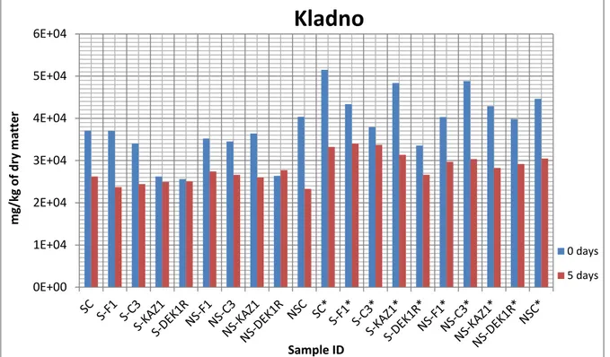
Figure 12 - NES values for sludge from Kladno ... 43
Figure 13 - NES values for sludge from Zličín ... 44
Figure 14 - NES values for the sludge from Brno ... 45
Figure 15- NES values for sludge from D1-Brno ... 46
Figure 16 - Three stage treatment ... 69
Figure 17 - Mechanical pre-treatment ... 69
Figure 18 - Real representation of the Mechanical pre-treatment ... 70
Figure 19 - VSSF CW ... 70
Figure 20 - Real representation of the VSSF CW ... 71
Figure 21 - HSSF CW ... 71
Figure 22 - Real representation of the HSSF CW ... 72
Figure 23 - OD at 630 nm measured with each sludge sample and HB with BSM and diesel ... 73
Figure 24 - OD at 630 nm measured with each sludge sample and HB with tap water . 73 Figure 25 - OD at 630 nm measured with each sludge sample and HB with glucose and tenzide ... 74
xii
Figure 26 - OD at 630 nm measured with each sludge sample and HB with BSM ... 74 Figure 27 - OD at 630 nm measured with each sludge sample and HB with BSM and glucose ... 75 Figure 28 - OD at 630 nm measured with each sludge sample and HB with tenzide and diesel ... 75 Figure 29 - OD at 630 nm measured with each sludge sample and HB with BSM, tenzide and diesel ... 76 Figure 30 - OD at 630 nm measured with each sludge sample and HB with BSM, glucose and diesel ... 76 Figure 31 - OD at 630 nm measured with each sludge sample and HB with BSM with tenzide ... 77
xiii
T
ABLE OFT
ABLESTable 1 – Stormwater pollutants ... 5
Table 2 - Nutrients removal efficiencies in different types of CWs ... 10
Table 3 - Examples of hybrid CWs used for different wastewater treatment (Vymazal 2013a) ... 12
Table 4 - Limit values and technical standards according to Decree No. 294/2005 ... 23
Table 5 - Location and designation of each stormwater runoff treatment systems ... 29
Table 6 - Biodegradation treatments for each sludge sample ... 33
Table 7 - Dilutions used for the microplate reader tests ... 35
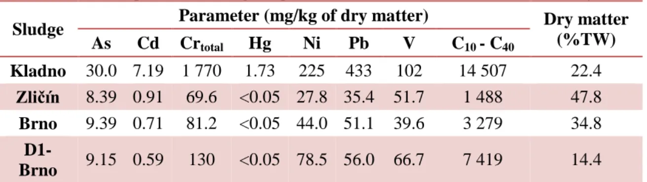
Table 8 - Initial values for the composition of each sludge sample collected from each stormwater runoff treatment system ... 41
Table 9 - OD variation of each sludge subjected to different conditions and lag phase time ... 48
Table 10 - Concentration of oil polluted water in a VSSF CW ... 51
Table 11 - Concentration of oil polluted water in a HSSF CW ... 52
Table 12 - Concentration of oil polluted water in a HCW ... 53
Table 13 - CFU counting for sludge sample from Kladno ... 66
Table 14 - CFU counting for sludge sample from Zličín ... 66
Table 15 - CFU counting for sludge sample from Brno ... 66
Table 16 - CFU counting for sludge sample from D1-Brno ... 66
Table 17 - Volume of HB added to 200 mL of saline solution for each sludge sample . 67 Table 18 - Microplate reader schema for the first test containing Kladno (sludge 1), Brno (sludge 2) and Zličín (sludge 3) ... 68
Table 19 - Microplate reader schema for the second test containing D1-Brno (sludge 4) and HB ... 68
Table 20 - NES values and dry matter for sludge from Kladno ... 78
Table 21 - NES values and dry matter for sludge from Zličín ... 79
Table 22 - NES values and dry matter for sludge from Brno ... 80
xiv
N
OTATIONBMPs – Best management practices BOD – Biochemical oxygen demand BSM – Bacterial standard medium CFU – Colony forming units CW – Constructed Wetland FWS – Free water surface HB – Halophilic bacteria HRT – Hydraulic retention time HSSF – Horizontal subsurface flow
ICP-AES – Inductively Coupled Atomic Emission Spectroscopy MC – Microbial community (Zličín, Brno, Kladno, D1-Brno, HB) MPN – Most probable number
MTBEs - Methyl tertiary-Butyl Ether NES – Non-polar extractable substances NW – Natural wetland
OD – Optical density
PAHs – Polycyclic aromatic hydrocarbons PCBs –Polychlorinated Biphenyls
SSF – Subsurface flow
TPH – Total petroleum hydrocarbons TSS – Total suspended solids
TW – Total weight
VOC – Volatile organic compounds VSSF – Vertical subsurface flow
1
1. I
NTRODUCTION1.1. Problem description
Water is an essential part of life. Increases in the world’s population and urbanization has led to increased water pollution and decreased water quality with effluents from domestic, municipal, agricultural and industrial wastewaters and stormwater runoff (Vymazal 2014). This requires the construction of drainage systems so that effluents can be subjected to proper treatment before being sent to rivers or lakes, thereby safeguarding ecosystems and public health (Barbosa, Fernandes, David 2012).
Stormwater runoff is considered a nonpoint source since it can originate from multiple sources, can be transported a long distance, has highly variable flows and a multitude of contaminants, including physical objects of different sizes and chemical contaminants, which complicate its management (Zhen et al. 2006).
The adverse effect of stormwater runoff was recognized in the 1960’s and there has been an increasing concern over its management. The main goal of the treatment of urban runoff is the reduction of sediment, nutrients and chemical pollutants before reaching natural waterbodies downstream. Since the treatment of stormwater is the main subject of this work, it is important to understand its origin, composition and some of the treatment options (Hallberg 2006; Geosyntec Consultants, Wright Water Engineers 2012).
The main goal of this thesis was to analyze the biodegradation behavior of different organic compounds by inocula from four sludges collected from four different stormwater runoff treatment systems along with the impact of halophilic bacteria (HB), in laboratory experiments. In addition, the treatment performance of a pilot scale constructed wetland operated with different flow regimes was also evaluated.
2
1.2. Thesis Organization
In order to better understand what this dissertation intends to address, a general outline is presented as follows:
Chapter 1
A general description of the difficulty of stormwater runoff treatment is made. The main objective of the present dissertation is also described.
Chapter 2
In this chapter, a description of the origin, composition and available treatment systems for stormwater runoff is mentioned. Attention is mainly focused on constructed wetland (CW) as a main treatment option for runoff water. Different types of CWs have different removal efficiencies according to the composition of the water to be treated. This section also includes various laws including discharge limits.
Chapter 3
This chapter includes the scope of the dissertation.
Chapter 4
This chapter includes information about the company where the laboratory work was done.
Chapter 5
This chapter describes the materials and methods used to obtain the expected results. It is divided into different procedures for the laboratory biodegradation tests and the pilot scale tests, including the microbiological analyses, operational flow regime, etc.
Chapter 6
The obtained results and their analyses are presented in this chapter.
Chapter 7
The recommendations to the company are listed here and take into account the obtained results and the initial objectives.
Chapter 8
3
2. S
TATE OF ART2.1. Origin of stormwater runoff
Urban stormwater or stormwater runoff are terms that define water from a rainstorm or a snowstorm that are measured in a downstream river, stream, ditch, gutter or pipe immediately after precipitation has occurred. It can also originate from water that percolated through the soil that later reaches a stream (Malaviya, Singh 2011). One important aspect of stormwater runoff is called “first flush”, where most of the particles present on impervious surfaces are transported during the first few millimeters of precipitation (Färm, Waara 2005).
Urbanization is contributing to the increasing amount of stormwater flow due to removal of vegetation and topsoil. This topsoil is being removed for the construction of new infrastructures such as buildings, roads and pavements. In addition, drainage systems are being installed underneath this new construction with the specific task of collecting urban discharges that come with the rainfall, and afterwards sending it to the receiving water.
The existence of these structures, which are made mostly of impervious material, contribute to the loss of the water-retaining functions of soil and vegetation. As such, this stormwater washes away pollutants and sediments from pastures, roads, houses, parking lots and other contaminants and sediments to the receiving water, leading to water quality degradation in these bodies (Barbosa, Fernandes, David 2012).
The majority of the compounds found in these effluents are generated from building materials, traffic releases (tires, brakes, de-icing agents), human activities and wet and dry deposition. Therefore, quality of the urban stormwater is highly influenced by the path that the drainage system takes (Eriksson et al. 2007).
2.2. Stormwater composition
Urban stormwater is composed of a multitude of different pollutants, including 78 metals and other inorganic elements and 385 xenobiotic organic compounds, heavy metals, biocides, nutrients and suspended solids (Eriksson et al. 2007). As such, these compounds can impact ecosystems due to issues associated with the toxicity and erosion in the recipient waters.
4
The composition and quantity of pollutants present in stormwater runoff depends on the season. For example, changes in temperature in winter influences snowmelt, and this also affects the flow and concentration of contaminants. In addition, pollution in receiving waters can also occur from the runoff of de-icing agents, which municipalities use during this period. In addition, studded “snow tires” are used instead of normal car tires to prevent aquaplaning. This also contributes to an increase in the wear of the asphalt pavement and particle transport (Hallberg 2006).
Stormwater runoff removes much of the contamination present on impervious areas that have been previously deposited during dry periods. It is also important to note that some persistent pollutants damage the drainage system and the roads itself, since pollutants accumulated in these infrastructures are not able to flow to the recipient water bodies when there is a short and intense summer storm, for example. In addition, if a sudden flush of road drainage occurs, all of the pollutants are suddenly drained and these shock loads may severely impact the recipient water body. Many factors can impact the amount of pollutants that are washed during a storm event. This includes the intensity and depth of rainfall, number of dry days before an individual storm and specific activities (construction, for example) in the catchment area (Malaviya, Singh 2011).
Most of stormwater priority pollutants are shown in Table 1. The lists presented in this dissertation does not include all of the parameters due to the extensive amount of pollutants identified in stormwater (Barbosa, Fernandes, David 2012; Malaviya, Singh 2011).
5
Table 1 – Stormwater priority pollutants
Pollutant group Measurement Parameter Range of Parameter
Concentrations Units Solids TSS 67-101 a mg/L Heavy Metals Cu 27-33 a µg/L Zn 135-226 a µg/L Cd 0.003 b mg/L Pb 30-144 a µg/L Cr 0.02 b mg/L Biodegradable organic matter BOD5 8-10 a mg/L Chemically oxidable
organic matter COD 40-73
a
mg/L
- BOD5/COD 0.14-0.2 mg/L
Organic Pollutants PAHs, PCBs, MTBEs, TPH
(diesel and gasoline) 10-35
c mg/L
Bacterial Indicators Fecal coliforms 103-104 b MPN/100
Nutrients Phosphorus 0.2-1.7
b
mg/L
Nitrogen 3-10 b mg/L
De-icing Agents NaCl and CaCl2
1521.02 c mg Na/L 6079.93 c mg Cl/L a (Tchobanoglous et al. 2003)
b (Zoppou 2001) c (Ying Zhang et al. 2013)
Nutrients like nitrogen and phosphorus are commonly generated from agricultural, commercial and urbanized areas through atmospheric deposition, traffic and construction sites. Nutrients from effluents and ample light support the growth of vegetation, which in turn allows for the occurrence of the conversion of inorganic chemicals into organic chemicals (Kivaisi 2001). However, such pollutants have negative impacts on human health and on natural ecosystems since they cause eutrophication, oxygen depletion and toxic effects towards flora and fauna (Wium-Andersen 2012).
Total suspended solids (TSS) are one of the most common parameters controlled in stormwater runoff since they are one of the primary causes of damage. Construction sites are responsible for the largest part of sediments in runoff. This is related to the high percentage of soil erosion, which is due to the absence of vegetation (Yannopoulos et al. 2013). Many other pollutants are also found in suspended solids in runoff, such as
6
metals, microorganisms, organic and inorganic compounds, since these contaminants are sorbed to these particles. Concerning this matter, it is important to understand pollutant partitioning in order to predict the fate and transport of solids and pollutants, as well to predict the treatment efficiency of sedimentation (Clark, Siu 2008).
During winter season, the use of deicers such as sodium chloride (NaCl) and calcium chloride (CaCl2) is usually applied to treat snow and ice on impervious surfaces for road safety, which prevents freezing of the pavement that compromises traction (Ying Zhang et al. 2013). As a result, there is an increasing amount of salt ions in stormwater runoff, especially Na and Cl, which may cause adverse impacts on ecosystems, including the interference in the normal uptake of salt of plants and organisms, and the growth of salt tolerant non-native plant species (Ying Zhang et al. 2013).
The most commonly found metals in highway runoff are copper, iron, lead and zinc, which are mostly washed off from roofs and trafficked areas (Opher, Friedler 2010). The presence of heavy metals in stormwater runoff is a concern because of toxicity and accumulation in soil and organisms (Liu et al. 2015).
Organic compounds are mostly present in particles and on VOCs (volatile organic compounds) that derive mainly from oil and grease. According to Malaviya and Singh (2011), the DayWater Project listed a group of organic chemicals that consisted of more than 50 compounds, seven of which could be considered potentially hazardous in water (ex. 2-ring compound naphthalene) and 35 in the solid phase (ex. pyrene and benzo[a]pyrene) (Malaviya, Singh 2011).
The presence of organic compounds in water stimulates the growth of bacteria, which biodegrade organic matter and consume dissolved oxygen. This process destroys fish populations and other aerobic aquatic species (Opher, Friedler 2010).
Oily substances are difficult to remove due to their low miscibility in water. This causes a higher concentration of these substances on the surface of the ground water and possible migration to areas outside of the contaminated site (Bozek et al. 2011).
Diesel fuel is one of the common organic pollutants found in stormwater runoff. It is a type of fuel constituted by a mixture of normal, branched and cyclic alkanes, and aromatic compounds. This pollutant is of interest due to its adverse effect on water quality and ecology, representing a permanent source of soil and water pollution. Due to
7
its mobility, diesel can cause considerable damage to water collectors or groundwater reservoirs (Xinying Zhang et al. 2013, Gallego et al. 2001). In general, oil concentrations in runoff collected from urban areas is usually between 10 and 35 mg/L. However, higher concentrations (up to 50 mg/L) can be detected from water collected from highways or motorways (Mažeikienė, Vaiškūnaitė, Vaišis 2014). More specifically, highway runoff may usually contain 0.12 to 13 mg/L of TPH, according to a characterization of stormwater runoff made in California (Kayhanian et al. 2007).
2.3. Stormwater treatment options
Since every ecosystem is affected by the quality of water resources, it is important to reduce and limit contamination of natural resources by adopting means of treating wastewaters. It is important to acknowledge the sources, pathways, loads and efficient treatment technologies in order to meet the ecological standards required by the receiving water bodies (Wium-Andersen 2012).
In order to mitigate the problems that stormwater runoff generates, structural or non-structural best management practices (BMPs) should be implemented through the adoption of techniques and measures that manage the quality and quantity of stormwater (Loperfido et al. 2014). Non-structural BMPs are used to control pollutants at the source to prevent or reduce runoff contamination. Structural BMPs retain runoff to settle or filter out the contaminants before entering receiving waters (Zhen et al. 2006).
Some of the examples of structural BMPs for stormwater runoff treatment are detention or retention ponds, wet ponds, infiltration trenches and basins, sand filters, grassed swales, buffer strips and CWs (Barbosa, Fernandes, David 2012; Zhen et al. 2006). They are grouped into nine fundamental processes of removal of particulate and soluble pollutants, including sedimentation, flotation, filtration, infiltration, adsorption, biological uptake, chemical treatment, degradation and hydrodynamic separation (Zhen et al. 2006). However, BMPs have recently been implemented to manage runoff near its source, emphasizing infiltration, retention on the landscape and incorporation with urban design (Loperfido et al. 2014).
Wet detention ponds have proven to be efficient and simple to operate and implement as a stormwater treatment technology, since it allows for flocculation, sedimentation and degradation, and thereby reduces the contaminant’s concentration
8
(Wium-Andersen 2012). In addition, when talking about cold climates, porous pavement, grassed swale, wet pond and percolation basins are considered the most appropriate, while dry basins, stormwater infiltration facilities and stormwater reuse are considered the least appropriate (Bäckström, Viklander 2000).
It is important to understand that the implementation of different stormwater runoff management systems is dependent on climate conditions, hydrology of the land, stormwater quality, conditions of the catchment area, and size of area available for treatment, among other influencing factors (Färm, Waara 2005).
The use of phytopurification or green technologies is gaining importance in wastewater treatment due to its cost effectiveness. The most common phytopurification technology is the constructed wetland, although it has only been recently implemented to treat stormwater runoff (Malaviya, Singh 2011).
2.4. Constructed Wetlands
United States Environmental Protection Agency defined CWs as “wastewater
treatment systems composed of one or more treatment cells in a built and partially controlled environment designed and constructed to provide wastewater treatment”
(EPA 1999).
Wetlands have been recently recognized for wastewater treatment, since they are the interface between terrestrial and aquatic ecosystems and exhibit characteristics of each. They are characterized by the presence of water, soils and the presence of plants adapted to their conditions (Scholz, Lee 2005). Different types of wastewater from diverse sources are treated, such as domestic wastewater, acid mine drainage, agricultural wastewaters, landfill leachate, urban stormwater, polishing advanced treated wastewater effluents to return to freshwater resources, eutrophic lake waters and for the conservation of nature (Kivaisi 2001).
Natural wetlands (NWs) have water filtration as the main function. Water flows through the wetland’s vegetation allowing suspended solids to attach and settle out. Meanwhile, existing microorganisms on the roots of plants perform the important task of transforming and removing pollutants from the flowing water or are converted into simpler forms that are taken up by plants or become inactive (EPA 2004). These wetlands tend to be in dynamic equilibrium with the adjacent conditions, so changes in the volume or quality of stormwater runoff can disturb the functions of a natural
9
wetland by altering the hydrology, water and sediment quality, or soil characteristics subsequently affecting its ecological functions (EPA 1996).
In order to respond to the demand of improved water quality, constructed or artificial wetland systems were built to substitute the NWs. CWs are artificial systems that use natural processes and involve wetland vegetation, soils and microbial populations to treat wastewater. It is important to note that CWs are different from NWs, since NWs only treat low volumes of wastewater, which limits their application as a treatment technology (Dordio, Carvalho 2014). Artificial ones are created based on the functions of NWs and adapted by increasing their size and by using a surface-flow system, which efficiently reduces or removes the concentration of nutrients, organic matter and suspended solids (Wetlands International 2003).
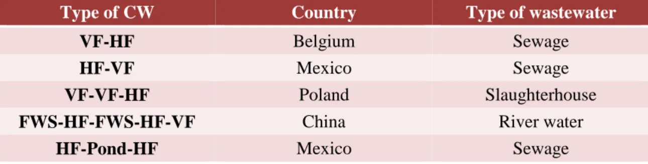
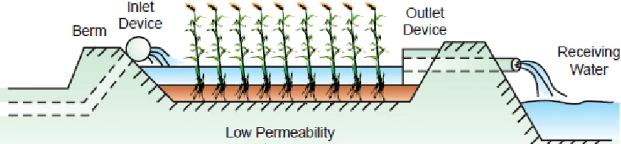
Although CWs can be used to treat raw wastewater, it is not recommended. They are normally used as a secondary treatment or in combination with other secondary treatment technologies (EPA 1999). Figure 1 illustrates a possible use of CWs for treating effluents.
Plants have a very important role in the biogeochemical cycle of environmental pollutants (Chen et al. 2015), since they affect the physical and chemical conditions within the rhizosphere in several ways. This includes altering the soil environment through root growth, increasing organic carbon availability through root exudation and decreasing water and nutrient through uptake (Bell et al. 2015).
2.4.1. Types of CW
According to Vymazal (2008), CWs are divided into two different types defined by water level, flow and direction of flow, such as free water surface (FWS) wetland and subsurface flow (SSF) wetland. Figure 2 compiles the different types (Vymazal 2008). Final Discharge Primary Effluent Secondary Effluent Raw Wastewater Primary Treatment Constructed Wetlands Secondary Treatment Desinfection or Tertiary Treatment
10
Figure 2 - Types of CWs (adapted from Vymazal, 2008)
Pollutant removal can vary according to the CW used. In the case of nitrogen and phosphorus, Table 2 represents the removal efficiency values of these contaminants for each CW.
Table 2 - Nutrients removal efficiencies in different types of CWs
CW Type Efficiency of Total
N removal (%) Efficiency of Total P removal (%) FWS 41.2 a 83.0 b HSSF 42.3 a 57.1 c VSSF 44.6 a 77.0 d a (Vymazal 2007) b (C. Pietro, Ivanoff 2015) c (Fu et al. 2014) d (Martín et al. 2013)
It should be noted that the best type of CW for the removal of nitrogen (N) is the vertical subsurface flow wetland (VSSF), while the removal of phosphorus (P) is best achieved by the free water surface wetland (FWS) (Table 2). In what concerns N metabolism, horizontal subsurface slow (HSSF) is good for denitrification process and VSSF for nitrification. In order to achieve a high removal efficiency of nutrients in CW, hybrid systems should be considered by integrating VSSF and HSSF (Vymazal 2007).
Yeh et al. (2009) examined metals removal from a FWS CW that used three tanks, where one was used as a control and the other two were hosting two different kinds of macrophytes. One of these two tanks was hosting cattails (Typha sp.) and the other was hosting reed (Phragmites sp.). The results showed that copper removal was approximately 80% while zinc removal was approximately 90%, although the different types of plants had limited influence on these rates (Yeh, Chou, Pan 2009). However, in
11
another study carried out by Cheng et al. (2002) of heavy metals efficiency removal by a twin shaped vertical/reverse-vertical flow (inflow/outflow) CW, heavy metal removal efficiency was approximately 100%, suggesting that this treatment unit can be used for water treatment with a low level of heavy metal pollution. However, care should be taken with the use of this system for drinking water, since the removal efficiency decreased after 80 days of usage (Cheng et al. 2002).
Greenway and Woodley (1998) tested nine pilot plant wetlands (eight FWS with different characteristics and one SSF) for municipal wastewater treatment with hydraulic retention times (HRT) from 2 to 17 days. The FWS removed up to 77% of TSS while the SSF only removed up to 50%. However, the SSF also had more efficient BOD removal, with concentration reductions reaching 89% (Greenway, Woolley 1999). Keizer-Vlek et al (2014) tested two different species of plants (Iris pseudacorus
L. and Typha angustifolia L.) in a free floating wetland for the removal of nitrogen and
phosphorus, respectively. Plant uptake contributed approximately 74% of total nitrogen removal and 60% of total phosphorus removal. In addition, the authors noted that harvesting plants should be an integral part of wetlands functioning since total nitrogen uptake by shoots was 4 times higher than root uptake and total phosphorus uptake by roots was negative (Keizer-Vlek et al. 2014). The rapid plant uptake of nitrogen resulted in nitrogen limitation, which affected the structure of rhizosphere bacterial communities (Bell et al. 2015). As shown in Figure 2, SSF and FWS can be integrated to form the so called hybrid constructed wetlands (HCW) in order to increase the removal efficiency of pollutants. HCW were first introduced by Seidel in the 1960s with the name of hydrobotanical method (Vymazal 2014). This system consisted of an infiltration bed with vertical flow (VF) and an elimination bed with horizontal flow (HF). However, this was not a widely used system at the time (Vymazal 2014). After approximately 20 years, this system was revived and built at several locations in Europe. Nowadays, it is known as the Seidel system, the Krefel system or the Max Planck Institute Process and consists of two stages of several parallel VF beds with Phragmites australis where nitrification and filtration take place. The VF beds were followed by two or three HF beds in series so that denitrification and organics and suspended solids removal could occur. Plants in HF beds included different kinds of emergent plants such as Iris,
12
types of HCW are more efficient in nitrogen removal than single HSSF or VSSF CWs (Vymazal 2013a).
In addition to the VSSF-HSSF type of HCW, another type was developed in the late 1990s, which combined the HSSF-VSSF but also included a sedimentation tank where the effluent was recycled. This was done in order to remove total nitrogen. Still another type combined more than two stages of CWs, including a FWS stage (Vymazal 2014). Many combinations are used to reach higher levels of removal efficiency of contaminants from different types of wastewater (Table 3) (Vymazal 2013a).
Table 3 - Examples of hybrid CWs used for different wastewater treatment (Vymazal 2013a)
Type of CW Country Type of wastewater
VF-HF Belgium Sewage
HF-VF Mexico Sewage
VF-VF-HF Poland Slaughterhouse
FWS-HF-FWS-HF-VF China River water
HF-Pond-HF Mexico Sewage
2.4.1.1. Free water surface (FWS) wetlands
FWS or surface flow wetlands are related to NWs, mimicking its hydraulic regime. Usually FWS wetlands are shallow basins containing 20 to 30 cm of rooting soil, which is mostly used to support plant growth. It also has a water depth of 20 to 40 cm where the wastewater is treated through sedimentation, filtration, oxidation, reduction, adsorption and precipitation processes (Vymazal 2013b). FWS has open water areas incorporated into its design in order to contribute to aesthetics, optimization of hydraulics and wildlife habitat (Kadlec 2009).
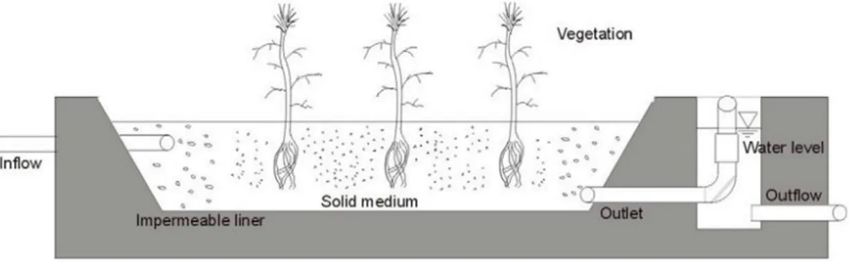
The influent water flows across the basin, which is visible at a shallow depth above the surface of the substrate materials. These materials are usually native soils and clay that prevent leakage (Figure 3).
13
Figure 3 - Configuration of a FWS wetland system (Wetland International 2003)
FWS wetlands are planted with different types of macrophyte plants, which include emergent, submergent and/or floating ones (Wong 2004). Common reeds (Phragmites australis), cattails (Typha spp.) and bulrushes (Schoenoplectus spp.) are typical emergent plants introduced in FWS wetlands and are commonly used in temperate regions (Nahlik, Mitsch 2006). However, natural seeds are allowed to be introduced in CWs to create a colony (Kadlec 2006).
Tropical treatment wetlands normally use free-floating macrophytes because of the lack of killing winters. These plants can be large with rosettes of aerial or floating leaves with well-developed submerged roots, such as water hyacinth (Eichhornia
crassipes) and water lettuce (Pistia stratiotes) or with few to no roots such as duckweed
(Lemnaceae) (Vymazal 2014). Free-floating macrophytes have a high capacity of nutrient removal, serve as a secondary carbon source as they decompose, and reduce the amount of sediment that accumulates within the system (Nahlik, Mitsch 2006).
Finally, submerged macrophytes play an important role in wetlands. They provide a refuge for herbivorous zooplankton against fish and maintain a clear water state in shallow lakes (Li, Huang, Zhang 2010). Some examples of submerged macrophytes are coontail (Najas guadalupensis), sago pondweed (Potamogeton
pectinatus), frog’s bit (Hydrocharis morsus-ranae) and European watermilfoil
(Myriophyllum spicatum). However, the use of CWs with submerged macrophytes is in the development phase (Vymazal 2014).
2.4.1.2. Subsurface Flow (SSF) Wetlands
SSF wetlands can also be called “root-zone method”, “rock-reed-filter”, “emergent vegetation bed system” (Wetland International 2003) or “vegetated submerged beds” (EPA 1999). It is a shallow basin or channel with an inlet and outlet structure. The bed is filled with porous material, which is made of a mixture of soil and
14
gravel or crushed rock for circulation of water and plant growth. The channel or basin has a barrier usually composed of clay and water that prevents leaching (Crites, Middlebrooks, Bastian 2014; Wetland International, 2003).
Compared to FWS, SSF has some advantages such as the smaller risk of odors or insect vectors, the larger available surface area for treatment and smaller area of installation (EPA 1993). However, they are susceptible to clogging and are not recommended for wastewater treatment with high concentrations of TSS (Malaviya, Singh 2011). According to Taylor and Francis (2006), the media and water depth range should be between 0.3 to 0.9 meters in the United States (Crites, Middlebrooks, Bastian 2014).
SSF CWs are divided into two different types according to the flow: the HSSF and VSSF(Vymazal 2014).
The HSSF CW (Figure 4) is a low cost system which employs gravel. This gravel has several advantages as it serves as a substrate to support the growth of plants and allows for the flow of water at approximately 100 to 150 mm below the plants. This allows for the contact between wastewater and microorganisms present in the rhizosphere(Laaffat, Ouazzani, Mandi 2015; Wetland International 2003). It usually has a bed depth of a maximum of 0.6 meters and the bottom of the bed is sloped to minimize flow above the surface (Malaviya, Singh 2011; Wetland International 2003). An example of a HSSF CW is shown on Figure 4.
VSSF CWs, also called infiltration wetlands (Malaviya, Singh 2011), are flat, vertically intermittently flooded and drained. This allows air to enter and fill the pores between the substrate. Wastewater can be inserted into the vertical wetland from the
15
upper layer to the lower layer (down flow) or backwards (up flow). Oxygen present in the pores may be transported to the lower layer (anaerobic layer at the bottom) of the wetland. This process allows for nitrification to occur while it complicates denitrification, since it is an anaerobic process (Scholz, Lee 2005). The total depth of the bed of VSSF CWs is usually in the range between 2 to 3 meters (Malaviya, Singh 2011).
A wetland’s vegetation can be naturally established, planted by nursery vegetation or by seeding (Malaviya, Singh 2011). For SSF wetlands, plants used are normally perennial emergent plants such as Phragmites australis (reeds) and Typha
latifolia (cattails, bulrush). Flowering species were initially planted for aesthetic
reasons, but since they have soft tissues that decompose quickly when the emergent portion dies, some locations adopted an annual harvest system to remove these plants before dying or simply chose to substitute them since these decomposing soft tissues affect water quality (Crites, Middlebrooks, Bastian 2014).
Phragmites is the most widely used genus of plants in European systems. It
offers many of advantages for a low maintenance treatment system since it spreads faster than bulrush and its roots go deeper than cattails (EPA 1993).
Substrate or bed media provides a path through which the wastewater passes, allowing for the survival of microorganisms by feeding on waste materials and subsequently treating it. In addition, it is used as a plant support in wetlands.
Saeed and Sun (2012) note that in order to permit nitrogen and organics removal, the media has to be able to provide aerobic and anaerobic pores inside the matrix to increase nitrification, denitrification and organics removal. In addition, media has to provide an internal carbon source to minimize the dependency of denitrification on the presence of available carbon in wastewater allowing the process to occur even when there is a low source concentration of carbon in the wastewater (Saeed, Sun 2012).
Wetland beds contain up to 0.6 meters of media that can be divided in two or more layers, which are usually gravel and soil (Zidan et al. 2015). The upper layer, composed by fine gravel, usually has a depth between 76 to 150 mm and serves as an initial rooting for the vegetation and is maintained in dry conditions (Crites, Middlebrooks, Bastian 2014).
16 2.4.2. Removal Mechanisms
2.4.2.1. BOD Removal
Biochemical oxygen demand (BOD) is the quantity of oxygen consumed during the biodegradation of organic matter. It is a very fast process in FWS, due to its quiescent conditions (Crites, Middlebrooks, Bastian 2014). However, the removal process is faster in SSF CW, since the decaying plants are not in the water column and consequently produce less organic matter in the effluent (Crites, Middlebrooks, Bastian 2014).
BOD is removed through physical processes such as sedimentation, flocculation, filtration or through biological decomposition in open water zones. However, when faced with anaerobic conditions, BOD would be removed through methanogenesis, sulfate reduction or denitrification (EPA 1999). Slow water flow allows SS and organic matter to settle, consequently minimizing BOD in the effluent (Malaviya, Singh 2011).
Soluble BOD can be removed by microbial growth or by attaching to the plant’s roots. Since BOD is produced due to decomposition of organics, wetlands and other wastewater treatment options can never achieve complete BOD removal. As such, typical effluent concentrations range between 2 to 7 mg/L (EPA 1993).
2.4.2.2. TSS Removal
The most used mechanisms of TSS removal are flocculation, sedimentation in the bulk liquid, and filtration in the interstices of the substrate or in the plants roots (Crites, Middlebrooks, Bastian 2014). It may occur due to death of invertebrates, fragmentation of plants, production of plankton and microbes within the water column or attached to plant surfaces. The formation of chemical precipitates such as iron sulfide may also occur (EPA 1999).
In FWS CWs, resuspension is also a problem within TSS removal since it may be generated by some turbulence caused by animals, high inflows or winds. Wetland vegetation controls this problem by reducing water column mixing (Vymazal 2014).
TSS removal is very effective in SSF CWs since most of the removal occurs within the first few meters of the inlet zone. Since SSF wetlands function as gravel filters, they provide a good environment for sediments to be separated by gravity
17
sedimentation, straining and physical capture, and adsorption on biomass film attached to gravel and root systems (EPA 1999).
2.4.2.3. Nitrogen Removal
Nitrogen removal in CWs is essentially made by nitrification and denitrification, physical settlement, plant/microbial uptake or through the harvesting of macrophytes (Vymazal 2014).
VSSF CWs are the most widely used systems in cases where a higher degree of filtration bed oxygenation and ammonia removal by nitrification is needed. However, VSSF CWs do not have the ability to simultaneously carry out nitrification and denitrification. This has led to the development and use of hybrid systems, which combine different types of CWs (Malaviya, Singh 2011).
For FWS CW, nitrification and denitrification are the primary removal mechanisms for nitrogen removal. The composition of a FWS allows for the presence of aerated (near the surface), anoxic and anaerobic (near the sediments) zones. Biomass decay provides the carbon source for denitrification and at the same time competes with nitrification for oxygen (Vymazal 2014).
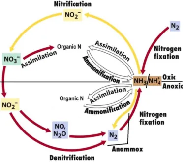
Nitrogen removal can occur through a series of chemical transformations from inorganic to organic compounds and on the other way around, requiring or releasing energy used by microorganisms. Figure 5 shows the biogeochemical cycle of nitrogen in aerobic (oxic) and anaerobic (anoxic) conditions.
18
Nitrogen fixation can occur in the anaerobic or aerobic soil layer, overlying water, rhizosphere of plant roots or on leaf or stem surfaces. It is the conversion of gaseous nitrogen (N2) to ammonia (NH3) by aerobic or anaerobic bacteria in the presence of enzymes (Scholz, Lee 2005; Vymazal 2007). As for nitrogen assimilation, it refers to biological processes which convert inorganic nitrogen, such as ammonia or nitrate, into organic compounds that can be assimilated from the sediments by emergent and rooted floating-leaved macrophytes and from water in the free-floating- leaved macrophytes (Vymazal 2007).
Concerning the ammonification process, organic nitrogen (organic N) is biologically converted into ammonia through a complex energy releasing process. In some cases the produced energy is used by microbes for growth and ammonia is directly incorporated in microbial biomass. Nitrification occurs in the oxidized rhizosphere of wetland plants, where ammonium (NH4+) is biologically oxidized to nitrite (NO2-) by strictly chemolithotrophic bacteria and subsequently to nitrate (NO3-) by facultative chemolithotrophic. In the anaerobic layer follows denitrification, where nitrate is converted into dinitrogen (N2), through intermediates nitrite, nitric oxide (NO) and nitrous oxide (N2O). There has been significant interest in enhancing bacterial denitrification in CW to reduce the level of eutrophication in receiving water (Scholz, Lee 2005; Vymazal 2007).
Another known mechanism of nitrogen removal in wastewater treatment systems is anaerobic ammonium oxidation (ANAMMOX). ANAMMOX is the anaerobic conversion of NO2- and NH4+ to N2 (Vymazal 2007). The extent of these reactions in CWs is still unknown.
2.4.2.4. Phosphorus Removal
Phosphorus removal in FWS CWs is a slow process that occurs through adsorption, absorption, complexation and precipitation (Vymazal 2013a). Phosphorus can be present in CW in different forms. Particulate phosphate is removed through sedimentation, sorbed on biofilms or entangled in emergent macrophytes, while soluble phosphate can be sorbed into plant biofilms in the water column or on the floating plant, or even on wetland sediments (EPA 1999). It can also be removed through uptake by microorganisms, including bacteria, algae and duckweed. The uptake process by the macrophytes occurs in the sediment pore water by the plant root system (EPA 1999).
19
Insoluble phosphates can be precipitated with ferric iron, calcium and aluminum (Malaviya, Singh 2011), however, this mechanism is limited by limited contact between the water column and the soil (Vymazal 2014).
According to Vymazal (2008), phosphorus removal may be limited in HSSF CWs since the media does not usually contain large quantities of iron (Fe), aluminum (Al) or calcium (Ca) that facilitate its precipitation or sorption (Vymazal 2014). In addition, there is limited contact between the media and wastewater, restricting effective phosphorus removal in SSF CWs (Crites, Middlebrooks, Bastian 2014).
It is important to note that some minerals from the media can provide temporary phosphorus removal through precipitation and/or sorption. Although, this only occurs for a short time period, since these processes are dependent on the source of sediments (EPA 1999).
2.4.2.5. Pathogens and Organic Compounds Removal
Pathogen removal is associated with TSS removal since they can adsorb to particles and be removed through sedimentation, interception and sorption (EPA 1999). Predation by protozoa and bacteriophages are also important ways for pathogen removal in CW (García, Paredes, Cubillos 2013).
Organic compounds are removed in wetlands through processes such as volatilization, sedimentation, aerobic and anaerobic bioremediation, adsorption and uptake (EPA 1999). The path that bioremediation of a pollutant takes depends on the environmental conditions, type of microorganisms, and structure of the chemical compound being degraded (Haritash, Kaushik 2009). Bioremediation may be defined as the use of biodegradative processes with the assistance of microorganisms to clean up soils and water polluted by organic pollutants (Gallego et al. 2001). Bacteria and fungi are important in the biodegradation of organic compounds since they transform these compounds into less toxic ones or into inorganic products such as, carbon dioxide and water (Sihag, Pathak, Jaroli 2014).
2.4.3. Microbiology
Microorganisms are an important part of wetland systems since they mediate most of mechanisms of pollutants removal (Baptista et al. 2008). Bacteria, yeasts, fungi,
20
protozoa and algae are types of microorganisms present in wetlands (DuPoldt et al. 1999).
There has been an increased attention towards the use of microbial consortia as a tool to improve bioremediation efficiency, since consortia can usually perform tasks that individual populations are not able to complete. This mechanism works because populations are able to communicate with each other through the trading of metabolites or molecular signals, which stimulates the response of each in the same consortia (Brenner, You, Arnold 2008).
Maverick et al. (2015) conducted a study where a specialized microbial consortia isolated from hydrocarbon polluted soil was introduced in a new and different environment (the CW) in order to evaluate the effect of diesel degrading microbial consortia on the rhizosphere of sweet flag (Acorus calamus L.), a common wetland plant. After testing, the authors concluded that the previously existing microorganisms in soil were as effective as the introduced ones for diesel oil removal (Marecik et al. 2015). Natural attenuation is an in situ treatment which is defined as the processes that occur in natural surroundings without the addition of microorganisms or amendments. These processes include biodegradation, diffusion, adsorption and other physical, chemical and biological mechanisms. Natural attenuation may reduce the toxicity and amount of pollutants and also control pollutant migration (Gallego et al. 2001), (Dong et al. 2015).
According to Baptista et al. (2008), there are three important microbial functional groups in the anaerobic removal of carbon in treatment systems: heterotrophic bacteria, sulphate-reducing bacteria and archaea (Baptista et al. 2008). However, additional functional groups may also be present, depending on the type of wastewater or water that is being treated. This includes halophilic microorganisms, which may be important in the removal of contaminants present in runoff wastewater. These microorganisms may easily adapt to the presence of high salinity wastewater (such as runoff wastewater). Pseudomonas mendocina, Burkholderia glumae and
Acinetobacter johnsonii are examples of halophilic bacteria (Wang, Xin, Gao, Li,
Morgan, Xing 2010).
Zhuang et al. (2010) based on Kushner (1978) defined different physiological groups of microorganisms according to their tolerance to a particular concentration of
21
salt: nonhalophiles (less than 0.2 M NaCl), halotolerant (nonhalophiles tolerating high-salt concentrations), slight halophiles (0.2 – 0.5 M NaCl), moderate halophiles (0.5 – 2.5 M NaCl) and finally, extreme halophiles (2.5 – 5.5 M NaCl) (Zhuang et al. 2010). It has been observed that significant hydrocarbon degradation occurred in the presence of 0.1 – 2 M NaCl suggesting that when faced with high salinity, these types of microorganisms are capable to degrade organic wastes.
The simultaneous use of plants and microorganisms to increase the efficiency of bioremediation is known as “rhizoremediation”. This process has been used for the degradation of organic compounds and uptake of heavy metals. The mechanism of remediation is based on the fact that plants stimulate the development of selected bacteria by releasing root exudates or by directly recruiting endophytic species, while microorganisms protect the plant from toxic pollutants or contribute to increased plant growth (Marecik et al. 2015). However, bioremediation can be improved by the use of bioaugmentation using a consortium of catabolically relevant microorganisms (Dueholm et al. 2015). Bioaugmentation focuses on taking advantage of microbial consortia specially designed for the specific physico-chemical properties of a bioprocess, in order to enhance the ability of the microbial community to degrade certain compounds (Herrero, Stuckey 2015; novozymes 2015).
2.4.4. Operation and Maintenance
The construction of artificial wetlands has to be well planned and maintained. In addition to the fact that wetlands provide wastewater treatment, they also promote the reutilization of water for individual or public use and at the same time serves as a wildlife habitat. Environmental impacts caused by the construction of wetlands such as the alteration of hydrology, introduction of invasive species and the disruption of natural plant and animal communities, can be avoided by following proper planning and construction techniques (Wetland International 2003; EPA 2004).
CWs are usually built on higher elevation areas and outside floodplains to prevent damage to NWs and other aquatic resources. CWs are built through excavating, backfilling, grading and installing water control structures to define the hydraulic flow patterns. Vegetation is then planted or naturally grows (EPA 2004).
22
In order to guarantee the performance and high efficiency of treatment of wastewater in CW, it is crucial to carry out operational and maintenance activities. Information needed in order to properly implement these activities include understanding the design and configuration of the used structures (along with the physical, chemical and biological removal mechanisms within), the quantity and quality of wastewater to be treated and the behavior of the receiving media (Turon et al. 2007). In addition, the operator has to pay special attention to the changes in water levels, maintenance of flow uniformity and berms/dikes, management of vegetation and control of odor and pests (EPA 1999).
If the operation and maintenance of the CW is not adequately carried out, problems may occur, which impact its functioning. These problems are usually related to the hydraulics of the system, such as loadings, clogging, supervision, misconceptions and/or bad design. For example, in VSSF CW, clogging of the filter surface is the biggest operational problem because it reduces the infiltration capacity and the oxygen supply, which subsequently affects treatment performance (Babatunde et al. 2008).
In order to respond to the operational and maintenance needs of a HSSF CW, Turon et al. (2007) developed and applied an Environmental Decision Support System (EDSS) that provided a monitoring notebook and an operating manual that includes measurements of specific parameters and preventive actions. In addition, the causes and corrective actions and the effects on the environment in case of failures were provided (Turon et al. 2007). As described in “A Handbook of Constructed Wetlands” by Luise Davis, management of CW should focus on providing a big opportunity for contact of water with the microbial community and with litter and sediment. This is needed in order to assure that the wastewater reaches every part of the wetland in order to maintain a healthy environment for microbes and growth of vegetation (DuPoldt 1999).
2.5. National legislation of Czech Republic
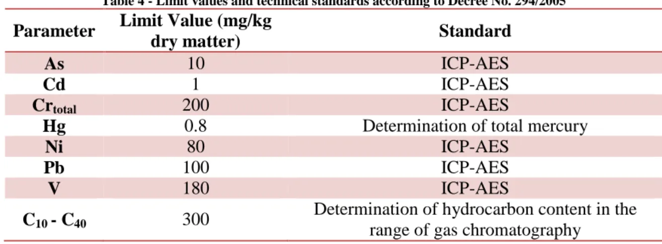
In order to analyze the concentration of pollutants present in each collected sample, the values present in Annex 10, Table 10.1. of Decree No. 294/2005 were used. It describes the directives for the conditions of depositing waste in landfills and its use on the surface of the ground and shows the maximum admissible concentration of pollutants in waste dried matter. Also shown are the technical standards for analytical determination of parameters (Table 4).
23
Table 4 - Limit values and technical standards according to Decree No. 294/2005
Parameter Limit Value (mg/kg
dry matter) Standard
As 10 ICP-AES
Cd 1 ICP-AES
Crtotal 200 ICP-AES
Hg 0.8 Determination of total mercury
Ni 80 ICP-AES
Pb 100 ICP-AES
V 180 ICP-AES
C10 - C40 300
Determination of hydrocarbon content in the range of gas chromatography
25
3. S
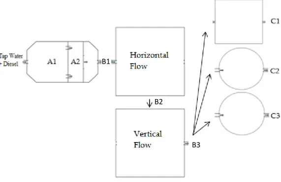
COPEThis work consisted of two different experimental tasks: 1) laboratory scale diesel biodegradation tests with the bacteria present in sludge samples collected from different stormwater runoff treatment systems and with halophilic bacteria (HB); and 2) pilot scale diesel biodegradation tests with a three-stage stormwater runoff purification technology composed of a mechanical pre-treatment, biological treatment and infiltration system.
The laboratory tests had the purpose of examining the microbial degradation of diesel using inocula from CWs and to understand how to enhance the efficiency of this process using bioaugmented HB isolates when the bacteria present in the sludge samples did not sufficiently reduce the concentrations of diesel.
The main objective of the pilot tests was to examine the treatment of a continuous input of surface runoff wastewater in a three stage mechanical-biological system. This surface runoff was simulated by the addition of fresh water, followed by diesel polluted water and finally more fresh water. This was done in order to simulate the recovery ability of the system to retain diesel inside the system.
This work was developed for three months as part of an internship at a company called Dekonta a. s located in Prague, Czech Republic. Information about Dekonta is presented in the next section.
27
4. C
ASES
TUDY–
D
EKONTAa. s.
Dekonta a. s. (afterwards only referred as Dekonta) is a renowned environmental company with considerable international experience that offers diverse environmental services, such as hazardous waste treatment and disposal, remediation of contaminated sites, nation-wide 24 hour environmental emergency response service, environmental consulting and laboratory services.
The company was founded in 1992 in the Czech Republic and started as a company specialized in bioremediation of contaminated soil.
Dekonta developed a project supported by the Technology Agency of the Czech Republic called “Development of technologies for road and other paved areas stormwater runoff cleaning”. This project started in 2013 and will last for three years.
This project focused on the development of a three-stage stormwater runoff purification technology that included mechanical pre-treatment, biological stage and tertiary treatment stage represented by an infiltration system. The proposed technology had the possibility of being adapted in order to respond to the variability and amount of stormwater runoff. The biological stage is constituted by a wetland area, including an aerobic and an anaerobic stage in which the elimination efficiency against contaminants will be increased by active inoculation by the select bacterial strains and wetland vegetation.
Biodegradation tests at a pilot scale developed in this dissertation were carried out as a part of this project.
29
5. M
ATERIAL ANDM
ETHODS5.1.Lab scale assay – diesel biodegradation tests
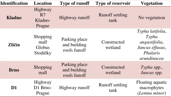
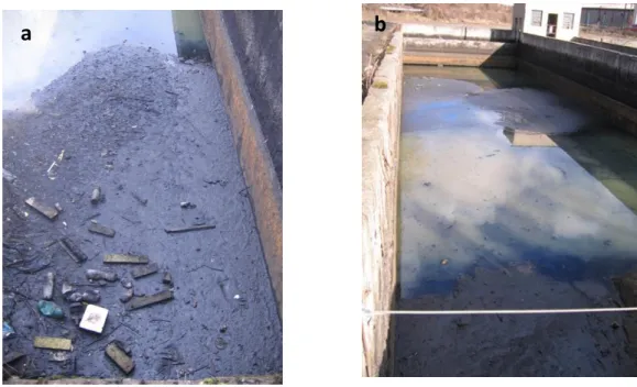
Four sludge samples from different located stormwater runoff treatment systems were collected from the upper 5 centimeters of the system’s soil and placed into sterile polythene bags and packed. They were carefully transferred to the laboratory for analysis and stored at 4ºC before processing. These samples were collected from stormwater runoff treatment systems located specifically in Kladno, Zličín, Brno and highway D1 (Brno) as explained in Table 5 and shown in Figures 6, 7 and 8. Collected samples were further used for the biodegradation tests in the lab.
Table 5 - Location and designation of each stormwater runoff treatment systems
Identification Location Type of runoff Type of reservoir Vegetation
Kladno
Highway R7
Kladno-Prague
Highway runoff Runoff settling
tank No vegetation Zličín Shopping mall Globus Stodůlky Parking place and building roofs funoff Constructed wetland Typha latifolia, Typha angustifolia, Juncus effusus, Phalaris arundinacea Brno Shopping mall Parking place and building roofs funoff Constructed wetland Typha spp., Juncus spp. D1 Highway D1 Brno-Prague
Highway runoff Runoff settling tank
Floating aquatic macrophytes (Lemna minor)
30
Figure 6 – a: Runoff settling tank located in Kladno empty; b: Runoff settling tank located in Kladno full
Figure 7 – Constructed wetland located in Zličín Figure 8 – Constructed wetland located in Brno
5.1.1. Bacterial density estimation
Initial tests were performed in order to determine the viability of the collected sludge. As such, 5 g of each sludge was added to 150 mL of BSM (bacterial standard medium) in separate 250 mL flasks. Experiments were setup in duplicate. BSM was