A Comparative Analysis of Fault Injection Methods
via Enhanced On-chip Debug Infrastructures
André Fidalgo, G. Alves, Manuel G. Gericota
ISEP / DEE
Rua Dr. Ant. Bernardino Almeida, 431
4200-072 Porto
+351 228 340 532
[ anf, gca, mgg ]@isep.ipp.pt
J. M. Martins Ferreira
FEUP / DEEC
Rua Dr. Roberto Frias
4200-465 Porto
+351 225 081 889
[email protected]
ABSTRACT
On-chip debug (OCD) features are frequently available in modern microprocessors. Their contribution to shorten the time-to-market justifies the industry investment in this area, where a number of competing or complementary proposals are available or under development, e.g. NEXUS, CJTAG, IJTAG. The controllability and observability features provided by OCD infrastructures provide a valuable toolbox that can be used well beyond the debugging arena, improving the return on investment rate by diluting its cost across a wider spectrum of application areas. This paper discusses the use of OCD features for validating fault tolerant architectures, and in particular the efficiency of various fault injection methods provided by enhanced OCD infrastructures. The reference data for our comparative study was captured on a workbench comprising the 32-bit Freescale MPC-565 microprocessor, an iSYSTEM IC3000 debugger (iTracePro version) and the Winidea 2005 debugging package. All enhanced OCD infrastructures were implemented in VHDL and the results were obtained by simulation within the same fault injection environment. The focus of this paper is on the comparative analysis of the experimental results obtained for various OCD configurations and debugging scenarios.
Categories and Subject Descriptors
D.3.3 [Performance and Reliability]: Reliability, Testing, and Fault.
General Terms
Performance, Reliability, Standardization, Verification.
Keywords
Dependability, Fault Injection, Real Time Systems.
1
INTRODUCTION
1.1
Problem definition
On-chip debug (OCD) infrastructures are increasingly common, particularly in highly complex microprocessors, where prototype validation contributes heavily to the total development effort. The
importance of standard OCD features has long been recognised by industry and led to various proposals in this area, namely the Nexus 5001™ Forum Standard for a Global Embedded Processor Debug Interface [1], the IJTAG P1687 proposal for access to embedded test and debug features [2], and the IEEE P1149.7 Compact JTAG (CJTAG), a test and debug interface proposed by the Mobile Industry Processor Interface (MIPI) [3].
The contribution of OCD infrastructures to shorten the time-to--market outweighs their overhead factors (e.g. silicon area, additional pins, etc.), even if used solely for debugging purposes. Moreover, the controllability and observability features provided by common OCD operations enable additional application areas. Read / write access to internal registers and memory may be used to inject faults and observe their effect upon system operation, enabling fault tolerance validation methods that may be used at various stages during the product life cycle. OCD infrastructures provide a low-cost straightforward solution for fault tolerance validation, but face limitations in various areas, e.g. bandwidth (fault injection operations per second), coverage (only a subset of the microprocessor blocks are within reach of the OCD operations), and representativeness (an OCD bit-flip operation may be masked by the current instruction as it executes). These limitations may be mitigated by enhanced OCD features addressing specific fault injection requirements.
Our comparative study considered three main OCD configurations, herein referred as basic, extended and OCD-FI. Each level was further subdivided according to specific fault injection scenarios, namely off-line / real-time, and predefined / on-the-fly determination of the faulty value. The OCD-FI scenario was further extended to cope with the presence of error detection and correction features, and real-time register access requirements. A common set of fault injection campaigns and workload applications was used to derive the comparative data that grades each OCD scenario.
1.2
Novelty
Parts of the R&D work that supported this paper have already been published, with an emphasis on design and implementation aspects. The basic, extended and OCD-FI configurations were described in [4]. The extended scenarios were presented in [5], and the bandwidth aspects were discussed in [6]. The novelty of this paper consists of presenting, for the first time, a comparative analysis of the partial results that correspond to the various OCD configurations, accompanied by an overall discussion concerning their pros and cons.
Permission to make digital or hard copies of all or part of this work for personal or classroom use is granted without fee provided that copies are not made or distributed for profit or commercial advantage and that copies bear this notice and the full citation on the first page. To copy otherwise, or republish, to post on servers or to redistribute to lists, requires prior specific permission and/or a fee.
1.3
Organization
OCD fault injection in microprocessors is the subject of the next section, and comprises the fault injection environment and scenarios, and a brief description of the enhanced OCD implementations. The core section of this paper then follows, presenting the experimental results of our comparative study. These results are grouped in three subsections, addressing the main OCD configurations (basic, extended and OCD-FI), their
extensions to cope with the presence of error
detection / correction features and with real-time access requirements, and a summary of performance and overhead issues. A final section presents the main conclusions of this work. Bibliographical and webliographical references close the paper.
2
OCD FAULT INJECTION IN
MICROPROCESSORS
2.1
The NEXUS fault injection workbench
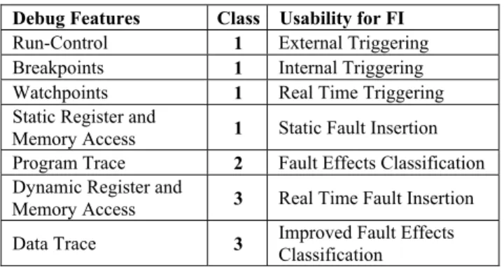
Several standardization efforts for OCD infrastructures and interfaces were initiated on recent years [2,3,7]. IEEE-ISTO 5001, The Nexus 5001 Forum Standard for a Global Embedded Processor Debug Interface [1], was the first of these efforts and is currently well documented and stable. NEXUS uses an IEEE 1149.1 compliant port, or alternatively a specific AUX port, which can be implemented in different versions depending on the desired bandwidth and port size. The communication protocol comprises a set of messages that support mandatory, optional and developer-defined messages. For maximum flexibility, four different classes of compliance are defined in the NEXUS proposal. Table 1 presents the debugging features that are required for fault injection purposes along with the compliance class where they are mandatory.
Table 1. NEXUS: Debugging Features Used for Fault Injection (FI)
Debug Features Class Usability for FI
Run-Control 1 External Triggering
Breakpoints 1 Internal Triggering
Watchpoints 1 Real Time Triggering
Static Register and
Memory Access 1 Static Fault Insertion
Program Trace 2 Fault Effects Classification
Dynamic Register and
Memory Access 3 Real Time Fault Insertion
Data Trace 3 Improved Fault Effects
Classification
Experimental results captured using the workbench represented in figure 1 constituted the reference data used in our study. This fault injection environment comprises an iSYSTEM IC3000 debugger (iTracePro version) and the Winidea 2005 integrated debugging software [8]. Fault injection campaigns were manually generated and translated into Winidea scripts.
Campaign Data refers to the scripts describing the fault injection experiments and Trace Data represents the program trace information output by the OCD and stored on the debugger for subsequent analysis and program flow reconstruction.
CPU Host Machine
(Pentium PC)
Debugger (Fault Injector)
Trace Data Data
Link Campaign Data
IC3000
OCD
MPC565 NEXUS
Figure 1. Fault Injection Environment (MPC565)
2.2
Enhanced OCD infrastructures
In addition to the workbench represented in figure 1, our experimental environment comprised a VHDL model of a 32-bit RISC CPU core with stack and interrupt support. This core was created with the cpugenerator building tool [9], and coupled to a set of enhanced OCD infrastructures that enable the fault injection methods compared in this paper. Three applications were used as workload: (1) a matrix adder (MAdder), (2) a vector sorter (VSorter) and (3) a generic LUT-based control algorithm (XControl). Only XControl requires external stimuli generation and I/O capabilities on the target. Each application was developed in two versions: normal and fault tolerant. Fault tolerance was implemented by duplicating data in memory and performing each arithmetic operation twice. The comparison of the results obtained from each arithmetic operation provides a limited degree of fault detection, with some overhead in execution time and memory requirements.
BUSES
OCD RCT
RWA MQM
AUX PORT
Bus Snooper CPU
core
ROM
RAM
I/O
Bus Master
FI
Figure 2. The OCD Infrastructure
receives commands from the MQM and RWA modules and outputs trace data and watchpoint hit signals. This module controls the CPU core clock and the signals required to identify branch and exception occurrences on the running application.
Three ODC configurations were implemented to support this comparative study: a lower bandwidth “basic” version (MDI = 2 bits, MDO = 8 bits); a higher bandwidth “extended” version (MDI = 8, MDO = 8); and an “OCD-FI” version that comprises a fault injection module. Apart from the setup of fault insertion data (triggering and location) and external analysis of the results, the autonomous OCD-FI solution enables full control of fault activation and insertion, without the need for external signals. The implemented OCD configurations are summarized in Table 2, which includes the MPC565 information for reference purposes.
Table 2. OCD Configurations used in our comparative study OCD
Configuration
CLK (MHz)
MDI (bits)
MDO (bits)
FI Module
READI 40 2 8 No
BASIC 30 2 8 No
EXTENDED 30 8 8 No
OCD-FI 30 2 8 Yes
(READI is the name given by Freescale to the MPC5XX NEXUS-compliant OCDs)
2.3
Fault injection campaigns
Each fault injection campaign is described by a single script and comprises a series of experiments carried out during system operation. The target behavior is monitored and information is recorded as comprehensively as necessary (and possible), to evaluate the effects of the inserted fault(s). The fault model consists of bit-flip faults, which are inserted at specific moments during program execution, in order to emulate the SEU effects. Faults can be injected in all resources accessible by the OCD, including memory, internal registers and IO registers. However, and since writing in the microprocessor registers is normally not possible in real-time, most fault campaigns target memory positions. In fact, the NEXUS proposal does not consider real time access to registers and common OCD implementations do not include it, as it would interfere with program execution. As a consequence, the injection of register faults can only be done by temporarily halting the microprocessor. Specific fault campaigns were executed targeting internal registers to determine for how long it was necessary to halt the microprocessor in order to evaluate the imposed delay and other negative effects on application execution.
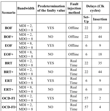
Better performance can be achieved by determining beforehand the value that will be present on the target memory cell at the fault insertion instant (herein referred as predetermination), but this requires: i) Complete knowledge of the program flow up to the fault injection instant; ii) Full observability of external inputs; and iii) Precise control of the fault injection instant and location. If predetermination cannot be guaranteed, it is necessary to read the target memory cell data immediately before the fault injection instant, in order to determine which faulty value shall be inserted to emulate an SEU. Each scenario offers various alternatives for this purpose, depending on relevant performance requirements. Table 3 presents the experimental scenarios that were used during our fault injection experiments. The name of each scenario
indicates the specific options selected, e. g. (B) basic OCD configuration, (E) extended OCD configuration, (OF) offline fault injection, (RT) real time fault injection, (+) no faulty value predetermination required and (FI) fault injection module present.
Table 3. Fault Injection Scenarios
Bandwidth Predetermination of the faulty value
Fault injection
method
Delays (Clk cycles) Scenario
Set-Up Insertion
BOF MDI = 2,
MDO = 8 YES Offline 22 35
BOF+ MDI = 2,
MDO = 8 NO Offline 22 44
EOF MDI = 8,
MDO = 8 YES Offline 6 9
EOF+ MDI = 8,
MDO = 8 NO Offline 6 18
BRT MDI = 2,
MDO = 8 YES
Real
Time 22 35
BRT+ MDI = 2,
MDO = 8 NO
Real
Time 22 44
ERT MDI = 8,
MDO = 8 YES
Real
Time 6 9
ERT+ MDI = 8,
MDO = 8 NO
Real
Time 6 18
OCD-FI MDI = 2,
MDO = 8 YES
Real
Time 57 2
OCD-FI+ MDI = 2,
MDO = 8 NO
Real
Time 57 4
2.4
EDAC and RTREG OCD extensions
Our comparative study also included OCD extensions to cope with (1) targets equipped with hardware fault tolerance mechanisms, and (2) situations where real time fault injection on internal registers is critical. To accurately test EDAC-based fault tolerance features it must be possible to emulate SEU effects by inserting single bit-flip errors into memory without affecting any other data or EDAC bits. As OCD infrastructures usually access memory through the EDAC mechanism, fault injection as envisaged is not possible, since single bit-flip errors are automatically corrected. It is therefore necessary to access memory directly and to take into account not only the data value, but also the extra error detection bits. The extension to the OCD-FI requires the ability to generate both the data to be written into memory and the codes used for error detection and correction. The OCD-FI (EDAC) extension is enabled and configured when the fault injection experiment is set up, and should be used whenever the fault targets EDAC protected memory areas.
counter). It can however be useful in situations where real time fault injection in internal registers is more important than performance issues, and where the coverage limitations are acceptable.
3
EXPERIMENTAL RESULTS
3.1
Basic, extended and OCD-FI scenarios
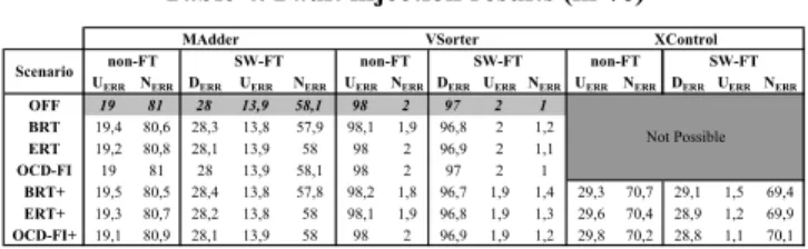
All modules were implemented in VHDL and synthesized using Xilinx’s ISE version 7. All simulations were run on post place--and-route models using Modelsim 6. Synthesis was executed identically for all components using balanced area versus performance settings. Due to debugger memory limitations, each fault injection campaign consisted of 10 experiments, injecting one bit-flip fault that emulates a single SEU. One hundred campaigns were executed on each scenario using our three target applications (MAdder, VSorter, XControl) in their normal and fault tolerant versions. Table 4 presents the results of the fault injection campaigns, classified by scenario and target application. All the scenarios that use offline fault injection (BOF, BOF+, EOF, EOF+) returned exactly the same results, which are presented on the first line of Table 4 (OFF row). Fault effects were classified into the following categories:
UERR: Undetected Error – an erroneous final result not detected by the (eventual) fault tolerance routine (all errors will be UERR if there is no fault tolerance routine)
DERR: Detected Error – the fault tolerance routine detected an error during execution. The application ended with an error detection signal.
NERR: No Error – the application ended correctly. This result includes both the errors that are still present in memory when the experiment ended and those overwritten by the running application.
Fault classification was performed after campaign execution, analyzing the contents of the debugger output memory. Trace information and the results of each application were compared with expected values to identify the occurrence of errors and their detection. The execution of all experiments listed above and the results obtained led to the following conclusions, relative to the controllability and observability of our proposed solutions:
All the configurations allow precise control of the memory address and bit where the fault is injected.
The instant when the fault is injected depends upon the delay between the occurrence of the trigger condition and the fault insertion instant. As this delay is constant and known for each configuration, it is possible to achieve precise control of fault insertion.
All experiments can be repeated on similar scenarios (i.e. using the same target application), on exactly the same conditions, and replicated as often as necessary.
The fault injection environment and operations have no effect on the target application execution before the fault is inserted into memory.
It is possible to use the trace information generated by the OCD to reconstruct program flow. Fault effect classification can be executed via the OCD using trace data and memory reads.
The OCD can be used for subsequent analysis of the final or intermediate results, and these tasks may be automated into the fault campaign scripts.
Table 4. Fault injection results (in %)
UERR NERR DERR UERR NERR UERR NERR DERR UERRNERR UERR NERR DERR UERR NERR
OFF 19 81 28 13,9 58,1 98 2 97 2 1 BRT 19,4 80,6 28,3 13,8 57,9 98,1 1,9 96,8 2 1,2 ERT 19,2 80,8 28,1 13,9 58 98 2 96,9 2 1,1 OCD-FI 19 81 28 13,9 58,1 98 2 97 2 1
BRT+ 19,5 80,5 28,4 13,8 57,8 98,2 1,8 96,7 1,9 1,4 29,3 70,7 29,1 1,5 69,4 ERT+ 19,3 80,7 28,2 13,8 58 98,1 1,9 96,8 1,9 1,3 29,6 70,4 28,9 1,2 69,9 OCD-FI+ 19,1 80,9 28,1 13,9 58 98 2 96,9 1,9 1,2 29,8 70,2 28,8 1,1 70,1
Not Possible MAdder VSorter XControl
SW-FT non-FT SW-FT Scenario non-FT SW-FT non-FT
To evaluate the discrepancies between real time fault injection scenarios, additional experiments were carried out, and those returning different results were replicated using extra debug operations, for this specific purpose. Each experiment was repeated with added data trace or, if necessary, with breakpoints immediately after fault insertion. Although this approach would be time-consuming for fault classification, it enables a finer analysis of the fault injection methodology. Erroneous fault insertions were classified as Inconclusive (INC), and represent the cases where the fault injection process was corrupted due to a microprocessor write access to the target cell during fault injection. Table 5 presents the percentage of inconclusive results found in each scenario.
Table 5. Occurrence of INC results (in %)
MAdder VSorter XControl MAdder VSorter XControl OFF
BRT 3,1 0,9 4 2,2
ERT 1,4 0,6 2,3 1,1
OCD-FI 0,2 0,1 0,2 0,2
BRT+ 3 1,2 2,1 4,8 2,8 3,2
ERT+ 2 0,8 1,5 3,7 2,1 2,4
OCD-FI+ 0,4 0,2 0,3 1,7 1,2 1,3
Not Possible
Scenario non-FT SW-FT
0 0
Not Possible
(the external I/Os used by XControl prevent predetermination, making fault injection campaigns impossible for the indicated scenarios)
The results shown above help us to understand the limitations of real time fault injection:
The OFF configurations always produce the most reliable results, as fault injection is performed when the target system is halted.
In some cases the CPU overwrites the target memory cell before the fault injection operation is complete. This leads to an erroneous fault injection and these experiments should be discarded (as an inconclusive result) for dependability evaluation purposes. Detailed analysis of the INC results showed that they mostly represent the injection of multiple bit-flips on the same cell.
3.2
Extensions (EDAC, RTREG) to the
OCD-FI scenario
Table 6 presents the results obtained with the OCD-FI (EDAC) extension, using only the non-fault-tolerant versions of the target applications. The DERR column indicates the percentage of errors detected that were corrected by the EDAC mechanism.
Table 6. FI results for a target equipped with EDAC (in %)
Derr Uerr Nerr INC Derr Uerr Nerr INC
MAdder 39,6 0 58,8 1,6 39,7 0 59,5 0,8
VSorter 98,3 0 0,8 0,9 99 0 0,7 0,3
XControl 29,9 0 69,1 1 30 0 69,5 0,5
no Predet Predet
The execution of fault campaigns using the EDAC extension provided the following additional conclusions:
The OCD-FI (EDAC) extension can be used to automatically inject faults into memory blocks protected by hardware fault tolerance mechanisms.
The use of an EDAC fault tolerance mechanism effectively eliminates the effects of single bit-flip errors on the target system, since they are all detected and corrected.
Table 7. FI results using the OCD-FI (RTREG) extension (in %)
non-FT SW-FT Uerr Nerr Derr Uerr Nerr MAdder 89 11 62 22 16
VSorter 60 40 46 14 40
The following conclusions are worth of mention:
When targeting CPU internal registers in real time, triggering must be adjusted to ensure that faults can be inserted before the running application attempts to write on the target register.
The instructions that can be used as fault triggers depend on the target microprocessor, the running application, and the target register. Their selection requires precise knowledge of the application code and instruction delays. For the accumulator register, using our workload applications, an average of 45% of the code could be used for triggering.
The fault injection results show that faults on the accumulator register differ significantly from faults in memory, depending on the target application. For instance, the percentage of undetected errors was higher for the MAdder application, and lower for VSorter (when comparing register and memory faults).
Similarly, software fault tolerance efficiency is also different and is application dependent.
The use of the RTREG extension shows that the injection of faults in internal registers is an important and complex problem. Registers are very sensitive to errors, and in critical systems it may be necessary to add extra hardware to protect them, and/or to more effectively test their sensitivity to faults. In some critical systems, adding on-chip support for register fault injection may be useful and justify the added intrusiveness and performance degradation.
3.3
Performance and overhead
Table 8 shows the maximum faults per second rates. The configurations considered were only those that do not require knowledge of the contents of the target memory cell, since it is no longer feasible to predict program flow after the first fault is injected. The values indicated assume that each fault is inserted separately (no multiple bit-flips on the same memory cell), and that the clock frequency is 30 MHz (typical value).
Table 8. Maximum faults / second rates Configuration Real
Time
Halted Access BOF+ 400k
EOF+
Not
possible 1150k
BRT+ 454k 400k
ERT+ 1250k 1150k
OCD_FI+ 491k 483k (real-time fault injection is not possible on Offline (OF) scenarios)
Real-time access provides little performance gain over halted access, as this last option was optimized to keep access delays as short as possible (access delays are considerably larger when using present-day commercial debuggers [10]). Nevertheless, the main advantage of real-time access relies on its low temporal intrusiveness, and would obviously be necessary on systems or applications were real time fault injection is mandatory or highly recommended.
The silicon overhead and the maximum operating frequency achieved on a Virtex-2 FPGA are summarized in Table 9. The reference scenario (shadowed line) is the case where only the CPU core and basic OCD infrastructure are implemented, since this is the typical COTS (Components-Off-The-Shelf) situation. The figures shown in this table refer to a target CPU that is a based on a RISC architecture using a limited instruction set. The use of more complex microprocessors would lower the OCD overhead, since the area required is mostly dependent on the debug features implemented, and on target bus widths (that should remain constant). In comparative terms, the extra overhead required for enhanced input bandwidth on the OCD (ERT) is fairly large (over 6%). Since the OCD-FI configuration presents much better results (less than 0,5%), it is preferable for real time fault injection purposes.
As would be expected, the inclusion of an EDAC mechanism slightly increases the microprocessor area, and also reduces its maximum operating frequency. The degradation of these parameters, imposed by the EDAC and the RTREG versions of the OCD-FI infrastructure, are however within acceptable limits, considering that they are intended for safety critical applications.
Table 9. Silicon overhead and dynamic performance
Area Sobrecarga Max f
Eq Gates % MHz
x 53926 75,4% 37
x x 55018 76,9% 32
x BRT 71527 100,0% 36
x BRT x 72619 101,5% 32
x ERT 76127 106,4% 36
x x 71842 100,4% 36
x +EDAC x 73184 102,3% 32
x +RTREG x 76392 106,8% 27
x +BOTH x x 77484 108,3% 25
4
CONCLUSION
The results obtained confirmed that our proposed solutions are an efficient alternative for injecting faults in memory, both in real time and offline scenarios. The best configuration depends on the target characteristics and dependability requirements. Offline fault injection is preferable for simpler scenarios (i.e. MAdder), and real time capabilities may be required for scenarios where external I/O must be included in the fault injection process (i.e. XControl).
For the fault model and the real time requirements that were considered, the most frequently used fault injection techniques are either software or radiation based. A comparison between these approaches and our proposed solutions may be made as follows:
Our solutions can be used either in simulation, in a programmable device (FPGA) or in an integrated circuit (ASIC), fitting the technology scenarios that cover the whole product development cycle.
The use of real-time is not justifiable by performance gains and should be used only when required by the target application. However, this is a capability where traditional fault injection techniques are often lacking and is a major advantage of the proposed technique.
Most hardware based real-time fault injection methodologies would be more complex and expensive to implement, and sometimes require a customized hardware version. Some of our proposed solutions require modifications to the target hardware, but their low overhead facilitates market acceptance.
Relative to radiation based fault injection or other contactless techniques, our proposed solutions have significant advantages in terms of experiment controllability and replicability. Precise control of fault location and injection instant is possible, facilitating experiment replication and deterministic results.
Software based techniques are more intrusive, present similar fault injection delays, and offer more limited coverage.
The need to handle erroneous fault classification results is common to all fault injection techniques, and more so when operating in real time. As in other approaches, problems can be minimized using statistical techniques or extra classification operations, whenever possible.
When compared with similar NEXUS-based real time fault injection techniques [10], our proposed solutions offer enhanced performance, with the subsequent minimization of inconclusive experiments. The fault injection campaigns used would not be possible on the MPC565 environment, due to the fast execution of each target application, when compared with the expected fault insertion delays. In fact, there are cases where the target applications run in less time than what would be required for the entire fault injection process, if using a commercial NEXUS debugger.
Some limitations are still present in our proposed solutions – coverage is limited to the resources accessible by the OCD, but
SEUs may also happen elsewhere. The lack of an accepted standard may impose a considerable tuning effort to adapt the debugger and the FI module to each particular case, but the trend towards OCD standardization will facilitate this effort. Presently, NEXUS is the most complete proposal, it is used in commercial devices and already provides useful features for fault injection purposes. However, it is not an approved IEEE standard and different technologies may be adopted in the future [2,3,7]. Assuming that watchpoints and data preloading are available, our proposed solutions are flexible enough to be adapted to different OCD infrastructures, and are adequate to support real-time fault injection in current and future OCD-equipped microprocessors.
5
REFERENCES
[1] “IEEE-ISTO 5001™ - 2003, The Nexus 5001™ Forum
Standard for a Global Embedded Processor Debug Interface”, IEEE Industry Standards and Technology Organization (IEEE-ISTO), 2003.
[2] IJTAG: A methodology for access to embedded test and debug features, on-line at
http://grouper.ieee.org/groups/1687/index.html (last visited on March 17th, 2008).
[3] R. Oshana and G. Swaboda “Compact JTAG (IEEE P1149.7) Overview of CJTAG, a Reduced Pin Debug Access
Protocol”, 5th IEEE Intl. Board Test Workshop, 2006.
[4] A. Fidalgo, G. Alves and J. Ferreira, “A Modified
Debugging Infrastructure to Assist Real Time Fault Injection Campaigns”, 9th IEEE Workshop on Design & Diagnostics of Electronic Circuits & Systems, 2006.
[5] A. Fidalgo, G. Alves and J. Ferreira, “Real-time fault injection using enhanced OCD: Performance analysis”, 21st IEEE Intl. Symp. on Defect and Fault Tolerance in VLSI Systems, 2006.
[6] A. Fidalgo, M. Gericota, G. Alves and J. Ferreira, “Using NEXUS compliant debuggers for real-time fault injection on microprocessores”, 19th Symp. on Integrated Circuits and Systems Design, 2006.
[7] The SPIRIT Consortium: Enabling Innovative IP re-use and design automation, on-line at
http://www.spiritconsortium.org (last visited on March 18th 2008).
[8] iSystem, On-Chip Debugging - In-Circuit Emulation - Custom Designs - Real-time & Test Automation, on-line at http://www.isystem.com (last visited on June 17th 2008).
[9] G. Ferrante, “CPUGEN 2.00”, on-line at
http://www.opencores.org (last visited on March 18th 2008).