Publishing House A K A P I T
C
OMPUTER
M
ETHODS IN
M
ATERIALS
S
CIENCE
Informatyka w Technologii Materiałów
Vol. 7, 2007, No. 4
A COMPARISON OF MODELS FOR DUCTILE FRACTURE
PREDICTION IN FORGING PROCESSES
CAI ZHENG1,JOSE M.A.CESAR DE SA1,F.M.ANDRADE PIRES1
1 IDMEC-Institute for Mechanical Engineering, Faculty of Engineering, University of Porto Rua Dr. Roberto Frias, s/n, 4200-465 Porto, Portugal
Corresponding Author: [email protected]; (J.M.A. Cesar de Sa)
Abstract
The possibility of predicting ductile fracture plays an important role in the design of components by forging proc-esses. Experimental observations showed that the nucleation, growth and coalescence of voids are the mechanisms that control the initiation and propagation of fracture and that these mechanisms are influenced in different ways by factors like the hydrostatic stress, the equivalent stress or by the maximal principal stress. Many ductile fracture indicators, based on some or all of those factors, are available and used in many practical situations in the design of those components. In this work a comparative work of many of those criteria was undertaken. Different criteria were chosen amongst the more popular ones and from different groups, in which they may be classified, namely those based on micromechanics and those based on the geometry of voids or their growth mechanisms. The criteria based on the Continuous Damage Mechan-ics, in which a coupling between plastic deformation and material degradation is taken into account and that include dif-ferent damage evolution descriptions for traction or compressive stress states, give a more correct and clear localization for the fracture initiation site.
Key words: Ductile fracture indicators, forging processes
1. INTRODUCTION
The possibility of anticipating the development of ductile fracture is an important issue in the design of parts obtained in forging processes. In particular the possibility of including reliable models in the numerical simulation of these processes that can predict the occurrence of ductile failure is of utmost importance as computer modelling plays a decisive role in the design, optimization and innovation of forging processes, involving more and more com-plex strain paths.
To reach that goal with success besides the ob-vious need of an efficient and reliable numerical model it is also necessary the adequate choice for a ductile fracture model. The utilisation of ductile fracture models was initially suggested, many
dec-ades ago, when a criterion based on the total plastic work was formulated by Freudenthal (1950). Some years later Kachanov (1958) proposed an alternative which has evolved to what is known nowadays as the Continuous Damage Mechanics. Since then many criteria have been put forward in one or the other of those two directions. In this work a com-parison of some of those different criteria is per-formed. In particular a ductile fracture criterion based on the Lemaitre´s damage model and on pre-vious work of the present authors in this field is shown to behave better than the others criteria.
2. DUCTILE FRACTURE INDICATORS
Ductile damage criteria intend to describe at the macro or meso scale the effect of phenomena occur-ring at the microscopic level, whether with the
re-C OMPUTER M ETHODS IN M ATERIALS S CIENCE
INFORMATYKA W TECHNOLOGII MATERIAŁÓW
course of experimental data or through physi-cal/mathematical models. Generally it is accepted that those criteria should take into account:
− the deformation path, because the current stress/strain state is not enough to characterise the damage state, (Cockcroft and Latham, 1968; Norris et al., 1978; Atkins, 1981; Atkins and Mai, 1985);
− the hydrostatic stress,
σ
H, because ductility grows rapidly asσ
H decreases, (Hancock and Mackenzie, 1976; Norris et al., 1978; Oyane etal., 1978; Lemaître, 1985; Mudry, 1985; Tai and
Yang, 1987);
− an adequate ratio of stresses, namely the triaxial-ity stress ratio,
σ σ
H / eq, in whichσ
eq is the equivalent stress, so that the general state of plasticity and fracture may be better described, (Mudry, 1985; Hancock & Mackenzie, 1976). Therefore, a ductile fracture criterion could be expressed in a general form as:(
)
P p 0 = H, eq,... d I εσ σ
ε
׺
◊ (1)where
I
◊ represents the fracture indicator,(
σ σ
H,
eq,...
)
◊
represents a certain fracturecrite-rion,
ε
p is the equivalent plastic deformation and.
indicates that the integration in only made on the positive component of the integrating function.The ductile fracture criteria may be classified in two big groups, namely those based on microme-chanics and those based on the growth of defects. Some of those criteria are briefly described in the next sections.
2.1. Criteria based on micromechanics
The criterion of total plastic work, also known as Freudenthal’s fracture criterion (Freudenthal, 1950; Gillemont, 1976), postulates that the initiation and propagation of a crack is dominated by a critical value of the absorbed plastic energy:
pf p p 0
=
=
d
wp eqI
W
εσ
ε
∫
(2)where Wp is the specific total plastic work,
ε
p is theequivalent plastic strain and
ε
pf is the equivalent plastic strain at fracture.The criterion of maximum plastic shear work was proposed in an attempt to reproduce the
mecha-nism of chip formation in orthogonal metal cutting. Most of the theoretical models (Ernst and Merchant, 1941; Lee and Shaffer, 1951) assume that the large plastic deformations take place along shear planes which may constitute the main phenomenon for chip formation. The criterion is given by
pf xy p xy max max 0
d
I
γ γ=
∫
τ
γ
(3) where xy maxτ
is the maximum shear stress in plane xy,p xy max
γ
is the maximum plastic shear strain ( in plane xy) andγ
pf is the maximum plastic shear strain at fracture.The criterion of equivalent plastic strain was proposed by Datsko (1966) and assumes that frac-ture is initiated when the equivalent plastic strain reaches a critical value as:
pf p p pf 0
d
I
ε ε=
∫
ε
=
ε
(4)where
ε
pf is the equivalent plastic strain at fracture.2.2. Criteria based on models based on the growth of defects
The mechanism of nucleation, growth and coa-lescence of voids is commonly accepted to be the reason for ductile fracture. The criteria inspired on that assumption may be based on different physical aspects, like the geometry of the voids, on the void grow mechanism or in constitutive material models. Some of those criteria will be referred next.
2.2.1. Geometry of defects
In the criterion proposed by McClintock (1968) the material is assumed to be divided in quadrilateral elements containing elliptical cylindrical voids. The criterion may be expressed by
(
)
pf 03
3
sinh
1 n
2(1-n)
2
a b b eqI
εσ
σ
σ
⎧
⎡
+
⎤
⎪
=
⎨
⎢
−
⎥
+
⎢
⎥
⎪
⎣
⎦
⎩
∫
p3
d
4
a b eqσ
σ
ε
σ
⎫
⎛
−
⎞
⎪
⎜
⎟⎬
⎜
⎟⎪
⎝
⎠⎭
(5)
where n is the exponent in the constitutive law
(
P)
ny0 0
y
σ
=σ
ε
+ε
andσ
a,σ
b may be taken as the principal stresses.Rice and Tracey (1969) established a criterion based on the analysis of the growth of spherical voids in a triaxiality stress state which is stated as
C OMPUTER M ETHODS IN M ATERIALS S CIENCE pf p 0 3 0.283exp d 2 H R eq I ε
σ
ε
σ
⎛ ⎞ = ⎜⎜ ⎟⎟ ⎝ ⎠∫
(6)and was reported to behave well in metal cutting processes.
2.2.2. Growth mechanism
The criterion proposed by Cockcroft and Latham (1968) assumes that the maximum principal stress is the most relevant in the initiation of fracture. This criterion is therefore defined in terms of traction plastic work associated to the principal stress along the path of the equivalent plastic strain as:
∫
ε σ = σ ε pf 1 0 P 1d I (7)Later Brozzo, De Luca and Rendina (1972), based on the evidence that ductility diminishes with the hydrostatic stress, included in the previous crite-rion an explicit dependence on
σ
H as(
)
∫
ε σ σ σ −σ ε σ = pf 1 0 p 1 1 d 3 2 H H I , (8)Norris et al. (1978) proposed an empirical criterion based only on the hydrostatic stress as
(
)
pf p 0 1 d 1-c H N H I ε σ=
∫
σ
ε
(9)where cN is a material constant. The authors claimed
that the fracture indicator could be, if conveniently calibrated, used as a measure of fracture toughness.
Having verified that the previous criterion did not properly describe fracture in deep drawing and forging Atkins (1981) introduced an explicit de-pendence on the deformation path as
p 0 d c -(1 2 1 1 pf ε σ + =
∫
ε ) H A L L I (10)where cA is a material parameter and L is the ratio
between the maximum and minimum plastic strain increments.
2.2.3. Material behaviour
Oyane et al. (1978) developed a material model for metal powders and porous metals which included an explicit dependence of the von Mises yield func-tion on the hydrostatic stress, the apparent density of the porous material and the matrix density. Adapting
and extending the basic theory they proposed a crite-rion for ductile fracture for porous and dense materi-als (Oyane et al., 1978 and 1980). The model as-sumes that fracture initiates when the volumetric deformations reach a critical value and takes the final form: pf p 0 1 1 d A v H Oy eq
I
ε εσ
ε
σ
⎡
⎛
⎞
⎤
=
⎢
+
⎜
⎜
⎟
⎟
⎥
⎢
⎝
⎠
⎥
⎣
⎦
∫
(11)where AOy is a material parameter.
The models based on the theory of Continuous Damage Mechanics may give an important insight into the analysis of fracture initiation and even to its evolution until failure (François, 1985; Murakami, 1990). In many situations even the damage variable has been used as failure indicator (François, 1985; Benallal et al., 1989; Murakami, 1990; Min et al., etc.). Cescotto and Zhu (1995) concluded that the damage variable is the only criterion that may pre-dict the site of fracture initiation.
Lemaître (1986) has suggested a criterion based on a critical value of the elastic energy release rate that could characterise the fracture initiation as:
(
)
(
) (
)
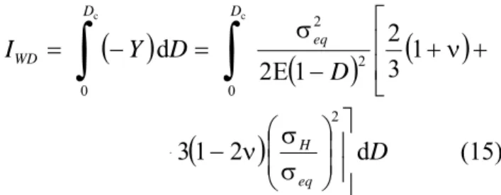
⎥⎥ ⎦ ⎤ ⎢ ⎢ ⎣ ⎡ ⎟ ⎟ ⎠ ⎞ ⎜ ⎜ ⎝ ⎛ σ σ ν − + ν + − σ = − 2 2 2 c 1 31 2 3 2 1 E 2 eq H eq D Y (12) where D is a damage variable and −Yc is the elastic energy release rate with damage at fracture.In the same direction Tai and Yang (1987), as-suming that the property that controls the initiation and evolution of a crack may be treated as a consti-tutive property of a material proposed a new fracture criterion based on the nucleation, growth and coa-lescence of voids as:
(
) (
)
p 2 D 1 31 2 d 3 2 p po ε ⎥ ⎥ ⎦ ⎤ ⎢ ⎢ ⎣ ⎡ ⎟ ⎟ ⎠ ⎞ ⎜ ⎜ ⎝ ⎛ σ σ ν − + ν + =∫
ε ε eq H V (13)where
V
D is the critical damage parameter.The observation of Lemaitre of the adequacy of using an energy measure as a ductile fracture crite-rion, and the characteristics that such a criterion should have, guided Vaz Jr. (1998) and Vaz Jr et al. (2001) to propose a fracture indicator based on the total damage work as
( )
Y
D
t
I
t WD d 0∫
− = & (14) orC OMPUTER M ETHODS IN M ATERIALS S CIENCE
INFORMATYKA W TECHNOLOGII MATERIAŁÓW
( )
(
D
)
(
)
D
Y
I
D eq D WD 1 3 2 1 E 2 d c c 0 2 2 0∫
∫
⎢⎢ ⎣ ⎡ + ν + − σ = − =(
)
D
eq H d 2 1 3 2 ⎥ ⎥ ⎦ ⎤ ⎟ ⎟ ⎠ ⎞ ⎜ ⎜ ⎝ ⎛ σ σ ν − + (15)where
I
WD represents the critical damage parameter.It is noteworthy that in this definition, which is consistent with the thermodynamics of irreversible processes, the parameter of energy release rate with damage,
−
Y
, contains the representation of thedamage state through the variable D, and takes also in consideration the hydrostatic stress through the triaxility factor σH σeq .
Andrade Pires et al. (2001, 2003) and César de Sá et al. (2002) extended this criterion in order to take into account the effect of crack closure under compression as:
( )
c 0 d D WDNI
=∫
−Y
D
=( )
(
)
c 2 2 0 1 1 : Tr E 1-DD
ν
ν
⎧ − ⎪ ⎡ + − ⎤− ⎨ ⎣ ⎦ ⎪⎩∫
σ
σ
σ
(
)
(
)
2 2 1 : -Tr d E1-h
h D
ν
ν
⎫ − ⎡ + − − − ⎤⎪ ⎬ ⎣σ
σ
σ
⎦ ⎪⎭ (16) In this criterion the energy release rate with damageis expressed in terms of principal stresses allowing to treat differently damage evolution for traction or compression stress states by means of a crack clo-sure parameter, h. This criterion, although computa-tionally more expensive, allows for the consideration of more complex strain paths, therefore approximat-ing better the real life formapproximat-ing processes.
3. ASSESSMENT AND COMPARISON OF THE DIFFERENT CRITERIA
Two examples will be used to assess and com-pare the different fracture indicators described. The geometry data, material properties and experimental conditions may be found in (Andrade Pires et al., 2003). In Figure 1 a schematic representation of each of the two tests is depicted.
The first example refers to a tension test of an axisymmetric notched specimen of an aluminium alloy subjected to monotonic axial stretching. In this example the deformation is highest near the notch
where the maximum value of the equivalent plastic takes place but fracture initiates at the centre of the specimen where the stress triaxiality ratio has its maximum value.
(a) (b)
Fig. 1. Test examples. (a) tension test of an axisymmetric notched specimen; (b) upsetting test of an axisymmetric speci-men.
The second example is the upsetting test of an axisymmetric specimen of a lead alloy reported in Gouveia et al. (1996). Here fracture initiation occurs in the external surface near the equator where trac-tion stresses are detected, revealing the importance of treating differently the damage evolution in trac-tion or compression.
The results obtained with the different criteria described in section 2 are presented in the next sec-tions.
3.2. Criteria based on micromechanics
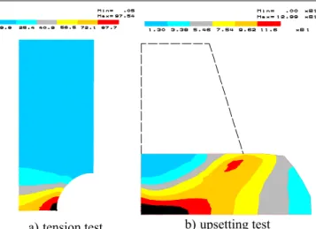
The analysis of the two examples with the crite-ria based on the total plastic work, on the maximum plastic shear work or on the plastic effective strain revealed them as inadequate and should, therefore, be dismissed as indicators of fracture. In fact in both examples they indicate a wrong localization for duc-tile fracture initiation as seen in Figures 2 to 4: in the tension test they predict fracture near the notch and in the compression test they predict fracture in the interior of the specimen. These criteria tend to indi-cate fracture in regions where plastic deformation concentrates, which in many cases do not corre-spond to what really happens in practice.
C OMPUTER M ETHODS IN M ATERIALS S CIENCE
a) tension test b) upsetting test Fig. 2. Criterion of total plastic work (Freudenthal, 1950; Gil-lemont, 1976).
a) tension test b) upsetting test Fig. 3. Criterion of maximum plastic shear work.
a) tension test b) upsetting test Fig. 4. Criterion of equivalent plastic strain (Datsko, 1966).
3.3. Criteria based on models based on the growth of defects
3.2.1. Geometry of defects
The two criteria based on the geometry of de-fects which were tested (McClintock,1968 and Rice
and Tracey, 1969), as seen in Figures 5 and 6, pre-dict the localization of fracture initiation inside the specimen in the tension test but in a very diffuse way, as the fracture zone extends in a large region. For the case of the compression test the criterion of McClintock (1968) shows the same feature as the fracture zone becomes very large, Figure 5, whilst the criterion of Rice and Tracey (1969) wrongly predicts the fracture initiation at the centre of the specimen, Figure 6.
a) tension test b) upsetting test Fig. 5. Criterion based on the geometry of defects – McClintock (1968).
a) tension test b) upsetting test Fig. 6. Criterion based on the geometry of defects – Rice & Tracey (1969).
3.2.2. Growth
mechanism
The criteria in which the growth of damage is based on the principal stress (Cockcroft and Latham, 1968, Brozzo et al., 1972), Figures 7 and 8, predict “correctly”, although in a very diffusive way, the fracture initiation for the case of the compression test where the principal stress plays an important role, but fail on the tension test where the triaxiality stress state is the main factor at failure.
The criteria based on the hydrostatic stress (Nor-ris et al., 1978, Atkins, 1981) fail in both tests,
Fig-C OMPUTER M ETHODS IN M ATERIALS S CIENCE
INFORMATYKA W TECHNOLOGII MATERIAŁÓW
ures 9 and 10. This fact indicates that although hy-drostatic stress is an important factor for fracture initiation it must not be taken exclusively as a pre-dicting factor.
a) tension test b) upsetting test Fig. 7. Criterion based on the growth of defects due to the maximum principal stress (Cockcroft & Latham, 1968).
a) tension test b) upsetting test Fig. 8. Criterion based on the growth of defects due to the maximum principal stress (Brozzo et al., 1972).
a) tension test b) upsetting test Fig. 9. Criterion based on the growth of defects due to hydro-static stress (Norris et al., 1978).
a) tension test b) upsetting test Fig. 10. Criterion based on the growth of defects due to hydro-static stress (Atkins, 1981).
3.2.3. Material behaviour
The fracture indicator of Oyane et al. (1978 and 1980), which is based on the assumption of a consti-tutive model for porous materials, predicts the re-gion of fracture in both tests but in a very large area as it may seen in Figure 11.
a) tension test b) upsetting test Fig. 11. Criterion based on the material model (Oyane et al., 1978 and 1980).
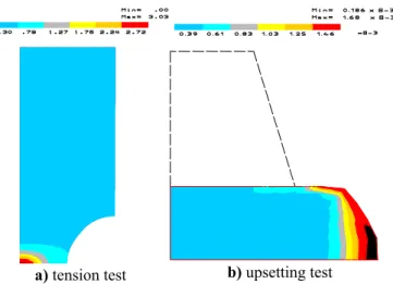
The criterion of Lemaître and Tay and Yang, which is based on the theory of Continuous Damage Mechanics, but with integration on the deformation path, predicts well fracture on the tension test but fails on the compression test as depicted in Figure 12.
The criterion proposed by Vaz Jr. (1998, 2003), which is also based on the theory of Continuous Damage Mechanics and Lemaitre damage model, is nevertheless substantially different from all referred before because the nominal fracture indicator is evaluated over the damage evolution path. More-over, it couples damage and plastic deformation at the constitutive level. For the case of the tension test
C OMPUTER M ETHODS IN M ATERIALS S CIENCE
it predicts very precisely the fracture initiation site, Figure 13. Nevertheless this promising new idea failed in the evaluation of the fracture initiation for the case of the compression test, Figure 13, where it predicted the fracture inside the specimen.
a) tension test b) upsetting test Fig. 12. Criterion based on Continuous Damage Mechanics (Lemaître, Tay and Yang, 1987).
a) tension test b) upsetting test Fig. 13. Criterion based on Continuous Damage Mechanics (Vaz Jr., 1998, 2001).
The criterion put forward by Andrade Pires (2001) and César de Sá et al. (2002), followed the proposal of Vaz, Jr. (1998) but introduced a slight change in the Lemaitre damage model used, by bringing in a crack closure effect by means of a pa-rameter, h, which allows treating differently damage evolution for traction or compression stress states. As it may be seen in Figure 14, in the detection of fracture initiation with this criterion, it is possible to account for the importance of, not only the triaxiality stress state as in the case of the tension test, but also the role played by the principal stress, namely when traction effects are predominant as in the case of the compression test. In both cases this criterion predicts accurately the localization of fracture initiation, as it may be seen in Figure 14.
a) tension test b) upsetting test
Fig. 14. Criterion based on Continuous Damage Mechanics (Andrade Pires, 2001, César de Sá et al, 2002).
4. CONCLUSIONS
The possibility of predicting ductile fracture plays an important role in the design of components by forging processes. Experimental observations showed that the nucleation, growth and coalescence of voids are the mechanisms that control the initiation and propagation of fracture and that these mechanisms are influenced in different ways by factors like the hydro-static stress, the equivalent stress or by the maximum principal stress. Many ductile fracture indicators, based on some or all of those factors, are available and used in many practical situations in the design of those components. Most of them are a-posteriori criteria, in the sense that they are used after the simu-lation of a forging process but without taking into account the progressive degradation of the material with the deformation.
In this work a comparative study was made of many of those criteria, using two test examples in which the main factors influencing fracture play different roles. The criteria based on the total plastic work, on the maximum plastic shear work or on the plastic effective strain behaved very poorly in both tests. The a-posteriori criteria based on the geometry of voids or on its growth mechanism whether failed in one the tests or showed a very diffused localiza-tion of the fracture site. Only the criteria that were based on the theory of Continuous Damage Mechan-ics, in which damage and deformation are coupled throughout the deformation history, could give a clear localization zone for fracture initiation. In par-ticular only the criterion proposed by Andrade Pires (2001) and César de Sá et al. (2002), which is fully based on the criterion proposed by Vaz, Jr (1998) but in which a different damage evolution is as-sumed for traction or compressive stress states,
C OMPUTER M ETHODS IN M ATERIALS S CIENCE
INFORMATYKA W TECHNOLOGII MATERIAŁÓW
could give the correct and clear localization for frac-ture initiation.
REFERENCES
Andrade Pires, F. M., 2001, Modelação por elementos finitos da iniciação da fractura dúctil nos processos de enformação plástica em massa, Master Thesis, Faculty of Engineering, University of Porto, Portugal.
Andrade Pires, F. M., César de Sá, J. M. A., Costa Sousa, L., Natal Jorge, R. M., 2003, Numerical modelling of ductile plastic damage in bulk metal forming, Int. J. of Mech. Sci., 45, 273-294.
Atkins, A. G., 1981, Possible explanation for unexpected depar-tures in hydrostatic tension-fracture strain relations, Metal Sci., 15, 81-83.
Atkins, A. G., Mai, Y.W., 1985, Elastic and Plastic Fracture, Ellis Horwood Ltd., Chichester.
Benallal, A., Billardon, R., Doghri., I., 1989, Numerical aspects of the damage and failure analysis of engineering structures, D.R.J. Owen, E. Hinton, & E.Oñate (eds.), Computational Plasticity: Models Software and Applications, Vol. I, 297-309, Swansea, Pineridge Press.
Brozzo, P., Deluca, B., Redina, R. A., 1972, A new method for the prediction of the formability limits of metals sheets, Proc.
7th Biennial Conf. Int. Deep Drawing Research Group.
César de Sá, J. M. A., Andrade Pires, F. M., 2002, Modelling of ductile fracture initiation in bulk metal forming, Proc. ESAFORM 2002, 5th ESAFORM Conference on Material Forming, eds., Pietrzyk, M., Mitura, Z., Kaczmar, J., Kraków, 2002, Publishing House AKAPIT, Poland, 147-150.
Cescotto, S., Zhu, Y. Y., 1995, Modeling of ductile fracture initia-tion during bulk metal forming, Computainitia-tional Plasticity – Fundamentals and Applications , eds., Owen, D.R.J., Oñate, E., Pineridge Press, Swansea, 987-998.
Cockcroft, M. G., Latham, D. J., 1968, Ductility and workability of metals, J. Inst. Metals, 96, 33-39.
Datsko, J., 1966, Material Properties and Manufacturing Process, John Wiley & Sons, New York.
Ernst, H., Merchant, M. E., 1941, Chip formation, friction and high quality machined surfaces, Surface Treatment of Metals, New York, ASM, 29, 299-378.
François, D., 1985, Fracture and Damage, Elasto-Plastic Fracture Mechanics, ed., Larson, L.H., Brussels. D. Reidel Publish-ing Co, 1-11.
Freudenthal, A. M., 1950, The Inelastic Behaviour of Engineering Materials and Structures, John Wiley & Sons, New York. Gillemont, L. F., 1976, Criterion of crack initiation and spreading,
Engng. Frac. Mech., 8, 239-253.
Gouveia, B. P. P. A., Rodrigues, J. M. C., Martins, P. A. F., 1996, Fracture predicting in bulk metal forming, Int. J. Mech. Sci., 38, 361-372.
Hancock, J. W., Mackenzie, A. C., 1976, On the mechanisms of ductile fracture in high-strength steels subjected to multi-axial stress-states, J. Mech. Phys. Solids, 24, 147-169. Kachanov, L. M., 1958, Time to the rupture process under the
creep conditions, Ivz. Akad. Nauk. SSSR, Otdel. Techn. Nauk., 8, 26-31.
Lee, E. H., Shaffer, B. W., 1951, The theory of plasticity applied to a problem of machining, J. Applied Mech., Trans. ASME, 18, 405-413.
Min, J. B., Tworzydlo, W. W., Xiques, K. E., 1995, Adaptive finite element methods for continuum damage modeling, Comp. & Struc., 58, 887-900.
Murakami, S., 1990, Role of continuum damage mechanics in fracture analysis, Inelastic Solids and Structures, eds, Kleiber, M., König, J.A., 67-80, Pineridge Press, Swan-sea.
Norris, D. M., Reaugh, J. E., Moran, B., Quiñones, D. F., 1978, A plastic-strain, mean-stress criterion for ductile fracture, J. Engng. Mat. Tech., Trans. ASME, 100, 279-286.
Lemaître, J., 1985, A continuous damage mechanics model for ductile fracture, J. Engng. Mat. Tech., Trans. ASME, 107, 83-89.
Lemaître, J., 1986, Local Approach of fracture, Engng. Frac. Mech., 25, 523-537.
McClintock, F. A., 1968, A criterion for ductile fracture by growth of holes, J. Appl. Mech., 35, 363-371.
Mudry, F., 1985, Methodology and application of local criteria for prediction of ductile tearing, in Elasto-Plastic Fracture Mechanics, eds, Larsson, H. L., Reidel, D., Publishing Co., Brussels, 1-11.
Oyane, M., Shima, S., Tabata, T., 1978, Considerations of basic equations and their aplication in the forming of metal powders and porous metals, J. Mech. Tech., 1, 325-341. Oyane, M., Sato, T., Okimoto, K., Shima, S., 1980, Criteria for
ductile fracture and their applications, J. Mech. Work. Tech., 4, 65-81.
Rice, J. R., Tracey, D. M., 1969, On the ductile enlargement of voids in triaxial stress fields, J. Mech. Phys. Solids, 17, 201-217.
Tai, W., Yang, B. X., 1987, A new damage mechanics criterion for ductile fracture, Engng. Frac. Mech., 27, 371-378. Vaz Jr., M., 1998, Computational approaches to simulation of
metal cutting process, PhD. Thesis, University College of Swansea.
Vaz Jr., M., Owen, D. R. J., 2001, Aspects of ductile fracture and adaptive mesh refinement in damaged elasto-plastic mate-rials, Int. J. Num. Meth. Eng., 50, 29-54.
PORÓWNANIE MODELI ZNISZCZENIA DLA PRZEWIDYWANIA PLASTYCZNEGO PĘKANIA
W PROCESACH KUCIA
Streszczenie
Możliwość przewidywania plastycznego pękania odgrywa ważną rolę w projektowaniu wyrobów kutych. Badania do-świadczalne pokazują, że zarodkowanie, wzrost i łączenie się pustek są mechanizmami kontrolującymi powstawanie i roz-przestrzenianie się pęknięć. Na te mechanizmy oddziałują, w różnym stopniu, takie parametry jak ciśnienie hydrostatyczne, intensywność naprężenia i maksymalne naprężenie główne. Znanych i używanych w praktyce jest wiele kryteriów pękania plastycznego opartych na tych parametrach. W niniejszej pracy te kryteria są porównywane. Spośród najbardziej popularnych wybrano kryteria pękania przynależne do różnych grup, klasyfi-kowane według podstaw danego kryterium, a więc kryteria oparte na mikrostrukturze materiału, kształcie pustek lub me-chanizmie ich wzrostu. Kryteria oparte na meme-chanizmie konti-nuum pękania, w których bierze się pod uwagę sprzężenie mię-dzy odkształceniem plastycznym i degradacją materiału poprzez analizę różnych możliwości rozwoju zniszczenia dla rozciągają-cego i ściskająrozciągają-cego stanu naprężenia, dają bardziej poprawną lokalizację obszarów, w których następuje inicjacja pęknięcia.
Received: October 8, 2007 Received in a revised form: November 6, 2007 Accepted: November 6, 2007