of Chemical
Engineering
www.scielo.br/bjcePrinted in BrazilVol. 35, No. 01, pp. 63 – 68, January – March, 2018
*Corresponding author: Luciane Godoi. E-mail: [email protected]; Phone/Fax: +55 (41) 33613197 dx.doi.org/10.1590/0104-6632.20180351s20160388
ELECTROREMEDIATION OF DEACTIVATED
CATALYSTS FROM FLUIDISED CATALYTIC
CRACKING FOR VANADIUM REMOVAL – THE
EFFECT OF A DUAL CATHODE CHAMBER
REACTOR
Luciane Godoi
1,*, Haroldo de A. Ponte
2, Maria José Jerônimo de S. Ponte
3,
Luciana S. Sanches
1, Renata Bachmann G. Valt
1and Raquel F. Leonel
41Federal of University of Paraná, Laboratory of Environmental Technology, P.O.Box 19011, Zip Code 81531-990 Curitiba-PR, Brazil
2Federal University of Paraná, Department of Chemical Engineering, Curitiba, PR, Brazil
3Federal University of Paraná, Department of Mechanical Engineering (DEMEC), Curitiba, PR, Brazil
4 Federal University of Paraná, PhD Fellow PRH24, P.O.Box 19011, 81531-990 Curitiba, PR, Brazil
(Submitted: July 4, 2016; Revised: October 31, 2016; Accepted: November 13, 2016)
Abstract – The aim of this study was to evaluate the quantity of vanadium removed through electrokinetic remediation
applied to catalyst waste used in a fluid catalytic cracking process. In excess, vanadium affects process efficiency
by reducing the catalyst’s activity, causing deactivation and reducing its useful life in petroleum cracking during
refining. The electrochemical reactor used was composed of an extra cathode chamber coupled with an ion-selective cation exchange membrane, Nafion®. The function of the cathode chamber was to increase the overpotential for a hydrogen reduction reaction (HRR) and the electric field to favour metal ion removal. Sodium citrate was used for electrolyte remediation (complexing vanadium) at 0.5 mol/L with an 11.0 V (ε =0.5 V/cm) potential applied. The treatment efficiency was analysed based on the vanadium ion concentration in the electrolyte collected. The results
show that electrokinetic remediation using the dual cathode chamber yielded more metal removal and lower energy consumption.
Keywords: Vanadium, FCC Catalysts, Electrochemical, Electrokinetic Remediation.
INTRODUCTION
Tons of deactivated catalyst are discarded by petroleum
refineries every day, which is a serious and cumulative
problem for the environment due to the presence of heavy metals in the catalyst (Afonso et. al., 2004). In addition to reducing risks to the environment and human health,
recovering these catalysts may generate significant profit
(Garcia and Bragança, 2009).
Heavy metals from petroleum impregnate the catalyst
structure during fluid catalytic cracking (FCC). These heavy
metals are considered contaminants or poisoners disturbing the catalytic activity of the material with reduction of catalyst
L. Godoi, H.A. Ponte, M.J.J.S. Ponte, L.S. Sanches, R. B. G. Valt and R. F. Leonel 64
2008). These catalysts are referred to as deactivated catalysts, E-Cat or equilibrium catalysts (Pinto et al., 2010).
To reduce the hazardous nature of this material, researchers are studying heavy metal removal from catalysts using electrokinetic remediation (Kaminari et al., 2007; Valt et al., 2015).
Electrokinetic remediation is a field method for removing
heavy metals as well as organic and organometallic compounds from contaminated soils (Acar et al., 1993; Afonso et al., 2004; Yeung, 2011). This technique can be applied to
catalysts with the same objective using a fixed bed reactor and
applying a low-intensity potential over a predetermined time
with a specific electrolyte for ion transport (Bockris, 2001;
Kaminari et al., 2007; Valt et al., 2015).
Certain chemical reactions occur during the electrokinetic process, such as the hydrogen reduction reaction (HRR) in the cathode, releasing OH- ions in the
electrolyte, and the oxygen oxidation reaction (OOR) in the anode, releasing H+ ions in the electrolyte. However, these
reactions raise the energy spent and provide an increase in
the electric field applied to the system. These conditions
also favour the precipitation of dissolved compounds due to pH variations when the local concentration of the compounds is higher than the solubility and/or dissolution limit of the precipitates (Krishna and Cameselle, 2009; Valt et al., 2015). Thus, the electrolytic solution pH in the anode compartment decreases due to the OOR reactions, and the anode solution becomes more acid as the pH reaches 2.0. On the other hand, the cathode compartment solution becomes more alkaline due to hydroxide ion production, which increases the solution pH to approximately 12. In both cases, the pH variation depends on the applied potential, the respective OOR (anode) and HRR (cathode) overpotentials and the separation of the HRR/OOR reactions, which facilitates a higher reaction overpotential and pH stability of the bed (Bockris, 2001; Sanches et al.,
2003; Wyrzykowski and Chmurzyńsk, 2010).
The use of ion-selective membranes in the electrokinetic remediation process makes it possible to reduce the OH- amount generated by using a different
catholyte with a higher reaction overpotential (Pletcher and Walsh, 1990; Machado and Santiago, 2014; Mattiusi et al., 2015).Therefore, a stronger electric field can be applied to the reactor without HRR and OOR reactions
and significant pH variations (about 8,2 -8,6). This
improved control over the electroremediation reactor
process yields a more efficient vanadium removal rate
and lower energy consumption.
Therefore, the aim of this work is to comparatively study vanadium ion removal from deactivated FCC catalysts through an electrokinetic remediation technique
in a porous fixed reactor using single and dual cathode
chambers with a 0.5 mol/L sodium citrate solution.
MATERIALS AND METHODS
Materials
The material studied here consists of a deactivated FCC catalyst composed of Y-zeolite, which was mainly composed of aluminium and silicon oxides with a tri-dimensional structure and saturated with several heavy metals, including vanadium.
The following materials were cut into racket shapes with an area of 0.01m2 and used as electrodes in the
electrokinetic remediation experiments. The distance between the electrodes was 22 cm. In the anode, a non-commercial electrode was used, which was manufactured by De Nora Company, composed of a 2-mm thick titanium
sheet covered with iridium and ruthenium (Ti = 66.75%; O= 22.4%; Ir = 9.14%; Ru = 1.71%); in the cathode, a
commercial electrode was used, which was composed of a
3-mm thick flat lead sheet.
The applied potential (ε =0.5 V/cm) was controlled by
a potential source of the brand Power Supply model EMG 18134 with a capacity to supply 30 V and 10 A.
A 0.5 mol/L sodium citrate solution was prepared
with distilled water (T = 25°C) and used as electrolyte.
The electrolyte was injected into the reactor chamber by using a Millan peristaltic pump with a power of 1.0 HP. To maintain the stability of the catholyte, 0.1 mol/L sodium chloride solution was recirculated in the extra cathode chamber of the second experimental setup.
Electrokinetic Remediation System
Two different electrokinetic remediation systems were used in this study: the first one with a cathode chamber,
and the second one with two cathode chambers separated
by a Nafion® cationic exchange membrane produced by
DuPont. The use of this membrane avoids the electrolytic pH changes, improving the reactor reaction stability.
The first experimental electrokinetic remediation unit
assembled is presented in Fig. 1, as used by Valt et al. (2015).
This first experimental unit was composed of an acrylic
chamber with a 600 g capacity of deactivated catalyst
(fixed bed). It included three upper orifices for electrolyte
sampling. The electrodes were positioned at the end of the reactor and connected to the power source. The electrodes
were separated from the porous fixed bed by a permeable
membrane. The electrolyte was injected into the anode
chambers by a peristaltic pump with a 60 ml/min flow rate.
Contaminated electrolyte was removed from the system through the cathode chamber.
The second experimental unit was similar to the
first one, used by Valt et al. (2015), but with a cationic
Figure 1. Schematic of the first electrokinetic remediation system components. (A) Electrolyte reservoir; (B) peristaltic pump; (C) acrylic
remediation chamber; (D) reservoir for the outflowing electrolyte; (E) power source; (F) anode chamber; (G) cathode chamber; and electrolyte
sampling points a, b and c (Valt et al., 2015).
Figure 2. Schematic of the second electrokinetic remediation system components. (A) Electrolyte reservoir; (B) peristaltic pump; (C) acrylic
remediation chamber; (D) reservoir for the outflowing electrolyte; (E) power source; (F) anode chamber; (G) first cathode chamber; (H) second cathode chamber; (I) cationic membrane; (J) sodium chloride solution inlet and outlet; and electrolyte sampling points (a, b and c).
The construction that held the cationic membrane consisted of the membrane, which was protected by two PVC plastic fabrics between two rubber sheets that were 0.4 mm thick with 30 Sh A hardness.
In both experimental systems (Figures 1 and 2),
the acrylic remediation chamber was entirely filled
with deactivated catalyst and 0.5 mol/L sodium citrate electrolyte. The system was maintained for 24 hours in standby to eliminate the air from the catalyst pores (Yeung,
2011; Valt et al., 2015).
A 0.1 mol/L sodium chloride solution recirculates in the extra cathode chamber of the second remediation system (Fig. 2) to renew the solution and remove the hydroxide ions generated by water electrolysis by-products, maintaining the reactor´s cathode pH closer to that of the reactor.
L. Godoi, H.A. Ponte, M.J.J.S. Ponte, L.S. Sanches, R. B. G. Valt and R. F. Leonel 66
8 hours and after 24 and 48 hours of the experiment. The pH was monitored in the reactor region next to the cathode.
The vanadium concentration in the sampled electrolyte during the electrokinetic remediation process, as well as
in the total final effluent of the process, was determined
by polarographic analysis using a Metrohm MVA-1 voltammetric analyzer with a HMDE system (hanging Mercury drop electrode).
RESULTS AND DISCUSSION
The current intensity measured during the experiments was maintained at the same order of magnitude in both systems (between 0.15 and 0.17 A). Considering the quantity of vanadium ions removed, this result indicates that energy consumption is lower when the extra cathode chamber is used because more vanadium ions were removed per unit of energy spent (energy consumption).
The sodium citrate electrolyte solution pH remained between 8.2 and 8.6 throughout all the experiment with the dual chamber system at all sampling points, unlike the experiment with the single chamber system in which the pH at point c changed from 8.2 to 12.7. In turn, the NaCl solution used in the dual chamber system showed a considerable increase of its pH after the second hour of experiment with a range of 7.02 to 13.3. The pH of the sodium citrate solution
remained below the threshold for vanadium precipitation, which is around 13, causing greater mobility of ions and reducing the reactions of RRH and ROO.
The results of the polarographic analysis show the vanadium
ion removal profiles over time in the different regions of the reactor during remediation for an ε =0.5 V/cm applied electric field with and without the dual cathode chamber.
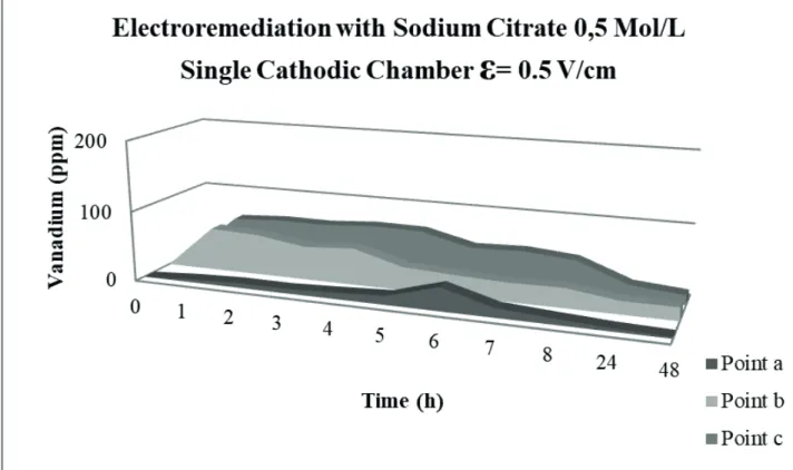
Fig. 3 shows the vanadium ion removal profile for
remediation by a single cathode chamber system.
Fig. 3 shows that more vanadium ions were removed at
Point b (centre of the reactor) in the first hours of remediation
with a removal peak of 61.0 ppm after 1 hour of the experiment and at Point C with a removal peak of 68.2 ppm after 4 hours of the experiment. After 48 hours into the process, Points b (central region) and c (region close to the cathode) continued to exhibit vanadium ion removal at approximately 15 ppm.
It was observed that the removal rate is stable with the greater vanadium concentration moving from the anode to the cathode. After 48 hours the migration rate decreases considerably, suggesting some process changes that need to be studied more.
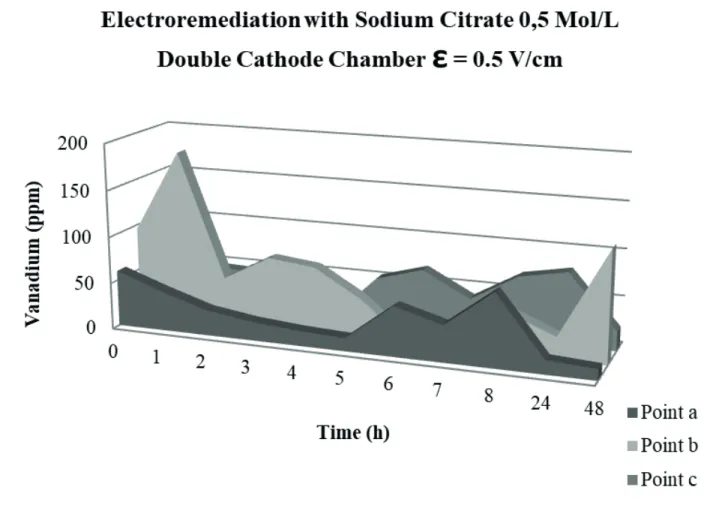
Vanadium ion removal increased considerably in the remediation experiment with the cationic membrane and second cathode chamber, as shown in Fig. 4.
A vanadium ion removal peak of 183 ppm was observed at Point a after 1 hour of remediation, and a removal peak of 78.7 ppm was observed at Point c after 24 hours of remediation.
Figure 3. Vanadium removal with 0.5 mol/L sodium citrate at the different sampling points in the electrokinetic reactor with the single cathode
Point a continued to exhibit the lowest removal average among the evaluated regions. Moreover, the vanadium ion concentration increased at Point b at the end of the experiment.
For both electrokinetic remediation systems, the single
cathode chamber and the dual chamber, with ε =0.5 V/
cm applied, the results were compared. The dual chamber showed a considerable increase in vanadium ion removal when sodium citrate was used, which demonstrates that the
dual chamber system featured a more efficient process.
With experimental time and electrolyte pH changes occur the solubilization of the species and metal ion complexation by citrate, which led to a slight increase in electrical current in the system, from 0.20A to 0.21A until the end of the experiment
The expected effect with the addition of the dual chamber was a better electric field profile and equalization.
The process electric current was reduced (0.13 A to 0.18 A at the end) and the amount of vanadium ions removed from the catalyst increased from 5.94 ppm, for the single chamber assembly, to 17.94 ppm for the double one.
Thus, there was a decrease in the process power consumption by using a double chamber assembly. The energy consumption calculated for the system with a
simple chamber was 184.8 Wh / kg and that for the dual chamber was 140.8 Wh / kg.
CONCLUSIONS
An analysis of the vanadium ion concentrations shows that vanadium removal with the dual cathode chamber
was more efficient than with the single chamber. The dual
cathode chamber also yielded lower energy consumption per unit of vanadium removed. Finally, the electrolyte pH was maintained at approximately 8.0 throughout the reactor in the dual cathode chamber system, which contributed to better vanadium removal.
In the experiment with the double cathodic chamber, the pH was strictly controlled and much more stable. This behavior was expected with the use of the cationic exchange membrane.
The analysis of the results obtained from this study showed that, although the electroremediation process was not able to remove all the vanadium from the catalyst, it presents a good potential for its treatment and the results support the application of the double cathodic chamber.
Figure 4. Vanadium removal with 0.5 mol/L sodium citrate at the different sampling points in the electrokinetic reactor with the dual cathode
L. Godoi, H.A. Ponte, M.J.J.S. Ponte, L.S. Sanches, R. B. G. Valt and R. F. Leonel 68
ACKNOWLEDGMENTS
We thank the financial support of the Brazilian Oil,
Natural Gas and Biofuels Agency (ANP), the Studies and Projects Funding Agency (FINEP), the Ministry of Science, Technology and Innovation (MCTI), Petrobras through the ANP Human Resources Programme for the Petroleum and Gas Industry (PRH-ANP/MCTI), and the National Council
for Scientific and Technological Development (CNPq).
REFERENCES
Acar ,Y.B.; Alshawabke, A. N.; Gales, R.J., Fundamentals of extracting species from soils by electrokinetics, Waste Management, 13,141- 151 (1993).
Afonso, J.C.; Pontes, A.B.; Santos, E.S.; Sousa, M.D., Reciclagem química de zeólitas comerciais desativadas, Química Nova, 27, 315 – 319 (2004).
Bockris, J.O’M., A.K.N. Reddy, Modern Electrochemistry 2B: Electrodics in Chemistry, Engineering, Biology and Environmental Science, 2, Springer Science & Business Media (2001).
Cerqueira, H.S.; Caieiro, G.; Costa, L.; Ribeiro, F.R., Deactivation of FCC catalysts., Journal of Molecular Catalysis A: Chemical, 2921, 292(1), 1-13 (2008).
Garcia, L.P.; Cruz, R.T.; Bragança, S.R., Use of catalyst waste
from hydrocarbon fluid catalytic cracking process in
alumina-silica refractories, Cerâmica ,55(334), 145-150 (2009).
Kaminari, N.M.S.; Schultz, D.R.; Ponte, M.J.J.S.; Ponte, H. A.; Marino, C.E.B. Neto, A.C., Heavy metals recovery from industrial wastewater using Taguchi method, Chemical Engineering Journal, 126(2), 139-146 (2007).
Krishna R. R., K. R. and Cameselle, C., Electrochemical Remediation Technologies for Polluted Soils, Sediments and Groundwater, John Wiley & Sons (2009).
Machado, M.d.B. and Santiago, V.M.J., Electrodialysis and
Water Reuse, Part 7: Electrodialysis Treatment of Refinery
Wastewater. Springer Berlin Heidelberg (2014).
Mattiusi, E.M. ; Kaminari, N.M.S. ; Ponte, M.J.J.S. ; Ponte, H.A.. Behavior analysis of a porous bed electrochemical reactor the treatment of petrochemical industry wastewater contaminated
by hydrogen sulfide (H2S). Chemical Engineering Journal, v.
275, p. 305-314 (2015).
Pinto, F.V.; Escobar, A.S.; Oliveira, B.G.; Lam, Y.L.; Cerqueira,
H.S.; Louis, B.; Pereira, M.M., The effect of alumina on FCC
catalyst in the presence of nickel and vanadium, Applied Catalysis A: General,388(1),15-21 (2010).
Pletcher, D. and Walsh, F.C., Industrial Electrochemistry. 2nd edition, London, GB, Chapman & Hall (1990).
Sanches, L.S.; Domingues, S.H.; Carubelli, A.; Mascaro, L.H., Electrodeposition of Ni-Mo and Fe-Mo alloys from sulfate-citrate acid solutions, Journal of Brazilian Chemical Society, 14(4), 556-563 (2003).
Valt, R.B.G.; Diógenes, A.N.; Sanches, L.S.; Kaminari, N.M.S.; Ponte, M. J. J. S.; Ponte, H.A., Acidic removal of metals
from fluidized catalytic cracking catalyst waste assisted
by electrokinetic treatment, Brazilian Journal of Chemical Engineering, 32(2), 465-473 (2015).Wyrzykowski, D. and
Chmurzyński, L., Thermodynamics of citrate complexation
with Mn2+, Co2+, Ni2+ and Zn2+ ions, Journal of Thermal Analysis and Calorimetry, 102, 61–64, (2010).
Yeung, A. T.; Milestone developments, myths, and future directions of electrokinetic remediation. Separation and