Phase constraint for the waves diffracted by
lossless symmetrical gratings at Littrow mount
Cristiano M. B. Cordeiro, Edson J. de Carvalho, and Lucila Cescato Physics Institute “Gleb Wataghin”–University of Campinas, 13083-970, Campinas, Brazil
Agnaldo A. Freschi
Department of Physics, University of the São Paulo State, 13500-970, Rio Claro, Brazil
Lifeng Li
Department of Precision Instruments, Tsinghua University, Beijing 100084, China
Received April 4, 2005; accepted April 22, 2005
The energy conservation of grating diffraction is analyzed in a particular condition of incidence in which two incident waves reach a symmetrical grating from the two sides of the grating normal at the first-order Littrow mounting. In such a situation the incident waves generate an interference pattern with the same period as the grating. Thus in each direction of diffraction, interference occurs between two consecutive diffractive orders of the symmetrical incident waves. By applying only energy conservation and the geometrical symmetry of the grating profile to this problem it is possible to establish a general constraint for the phases and amplitudes of the diffracted orders of the same incident wave. Experimental and theoretical results are presented confirming the obtained relations. © 2006 Optical Society of America
OCIS codes: 050.1950, 050.5080.
1. INTRODUCTION
In the past forty years different methods have been suc-cessfully employed to solve the diffraction problem of sur-face relief gratings. The main purpose of these theories has been the calculation of the diffraction efficiencies as a function of the grating parameters, such as depth, period, and shape of the profile. In recent years, however, many applications of surface relief gratings in resonant and subwavelength domains as polarizing elements have been developed. For the design of such elements the phase of
the diffracted waves plays a crucial role.1,2Most theories
allow the calculation of such phases; however, the abso-lute phase values have no physical meaning, and only the relative phase differences are experimentally measurable. In order to check the theoretical phase calculations, reci-procity and energy conservation were used to establish phase constraints for some particular cases involving only
four diffracted orders.3,4
In this paper we obtain a general constraint for the phases of the diffracted waves by applying only energy conservation and geometric symmetry for a lossless grat-ing at symmetrical Littrow mountgrat-ing. Experimental and theoretical results are presented confirming the obtained relations.
2. WAVE MIXING CONDITION OR
SYMMETRICAL LITTROW MOUNTING
If a symmetrical grating (of period⌳) is illuminated
si-multaneously and symmetrically by two coherent waves
(fieldsErandEs) of the same wavelength and at the
first-order Littrow mounting (= −L and L, respectively),
then from the grating equation, in theith direction of
dif-fraction there is a superimposition of two diffracted fields,
Er共i兲, and Es共i−1兲. Such a situation is illustrated in Fig. 1
for the transmitted orders (the reflected orders are omit-ted for simplicity). The total number of existing
transmit-ted orders共2N兲 and reflected orders共2M兲depends on the
wavelength-to-grating period共⌳兲ratio and on the
refrac-tive index of the grating material.
This sum or superimposition is also called wave
mixing,5and the resulting irradiance in theith diffraction
direction is given by
Ii=C兩Ei兩2=Ir共i兲+Is共i−1兲+ 2
冑
Ir共i兲Is共i−1兲cos共+r共i兲−s共i−1兲兲,共1兲
withCbeing a constant that depends on the refractive
in-dex of the media and Ei the sum of the two diffracted
fieldsEr共i兲, andEs共i−1兲.is the phase difference between
the incident waves, which represents the phase shift be-tween the grating itself and the interference pattern
gen-erated by the two incident wavesErandEs.is the phase
of each diffracted wave, caused by diffraction. Ir共i兲 and
Is共i−1兲are the irradiances of the diffracted wavesEr共i兲and
Es共i−1兲, and Ir and Is are the irradiances of the incident
wavesErandEs, respectively.
If the grating is lossless, the sum of the irradiancesIiin
all the existing diffraction directions (reflected and trans-mitted) must be equal to the sum of the irradiances of the
incident waves Ir+Is. Using the superscripts T for the
transmitted orders andRfor the reflected orders, this en-ergy conservation can be written as
兺
i=−N+1N
关IrT共i兲+ITs共i−1兲+
冑I
rT共i兲I s共i−1兲T cos共+ r共i兲
T − s共i−1兲
T 兲兴
+
兺
i=−M+1 M
关IrR共i兲+IsR共i−1兲+
冑I
rR共i兲IRs共i−1兲cos共+Rr共i兲−sR共i−1兲兲兴=Ir+Is. 共2兲
The irradiances of the diffracted waves can be written in
terms of their diffraction efficienciesas
IRr共i兲=Rr共i兲Ir, 共3兲
ITr共i兲=Tr共i兲Ir, 共4兲
IRs共i兲=Rs共i兲Is, 共5兲
ITs共i兲=Ts共i兲Is. 共6兲
By using the fact that for a lossless grating, energy con-servation must be valid for each individual incident wave
EsandEr, we have
兺
i=−N+1N
sT共i−1兲+
兺
i=−M+1M
sR共i−1兲= 1, 共7兲
兺
i=−N+1N
rT共i兲+
兺
i=−M+1 M
rR共i−1兲= 1. 共8兲
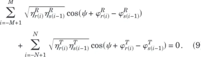
Substituting Eqs. (3)–(8) into Eq. (2), it is possible to ob-tain the following general constraint relating the phases and the diffraction efficiencies of all existing diffraction orders of a lossless grating at Littrow mounting:
兺
i=−M+1M
冑
rR共i兲 s共i−1兲R cos共+ r共i兲
R − s共i−1兲
R 兲
+
兺
i=−N+1 N
冑
rT共i兲 s共i−1兲T cos共+ r共i兲
T − s共i−1兲
T 兲= 0. 共9兲
If the grating presents a symmetrical profile (in rela-tion to the bisector of the incident beams), the diffracrela-tion
efficiencies and the phases of the symmetricalErandEs
incident beams must be equal:
r共i兲=s共−i兲, 共10兲
r共i兲=s共−i兲. 共11兲
Thus the constraint relation expressed by Eq. (9) simpli-fies to
兺
i=1 M冑
sR共−i兲sR共i−1兲cos共sR共−i兲−sR共i−1兲兲+
兺
i=1 N
冑
Ts共−i兲sT共i−1兲cos共Ts共−i兲−sT共i−1兲兲= 0. 共12兲This general constraint relates the phases and the ampli-tudes of all existing diffracted orders of the same incident
Eswave共= +L兲for a lossless symmetrical grating. A
cor-responding result can be obtained for theEr共= −L兲
in-cident wave. This constraint can be used to check the phase and amplitude values of the diffracted waves calcu-lated by any theory.
Although the same constraint expressed by Eq. (12) can be derived in grating theory from the unity of the
scatter-ing matrix for a lossless gratscatter-ing,6 the above derivation
gives a better physical insight into such phases. The analysis of the distribution of the energy between the dif-fracted orders allows, for example, previewing the phase difference behavior as a function of the geometrical pa-rameters of the grating.
Applying the constraint relation to a grating whose pe-riod is small enough to allow just four diffracted orders (the minus first and the zeroth diffracted orders by trans-mission and by reflection) produces
冑
−1R 0 Rcos共−1 R −
0 R兲+
冑
−1 T
0 Tcos共
−1 T −
0
T兲= 0. 共13兲
This relation represents the same phase constraint
ob-tained by Botten3and Bottenet al.4by using the principle
of reciprocity, energy conservation, and the symmetry properties of lossless diffraction gratings.
If the grating is a perfectly conducting grating (totally reflecting grating), the efficiencies of the transmitted or-ders are null; thus
−1R −0R=m+/2, 共14兲
withmbeing an integer.
The same occurs if the diffraction efficiencies of the re-flected orders are negligible, as for example in the case of a volume grating (Bragg grating). In this case,
−1T −0T=m+/2. 共15兲
This/ 2 value of the phase difference between the first
and zeroth diffracted orders is a well-known result from
the coupled wave theory7 for dielectric volume gratings.
The same/ 2 phase value appears in the scalar
diffrac-tion theory8 as the phase difference between successive
orders diffracted by phase gratings.
From the above results we can expect that the phase difference between the first and zeroth orders deviates
from the/ 2 value if the diffraction efficiencies of the
re-maining diffracted orders are not negligible.
3. THEORETICAL RESULTS
The theoretical phases and amplitudes of diffracted waves were calculated for gratings of three different
peri-ods (⌳= 0.4, 0.6, and 0.8m) as a function of the grating
depth by using the coordinate transformation method (the
C method).9A sinusoidal relief grating at Littrow
mount-ing was assumed with TE polarization and wavelength
= 457.9 nm. For the dielectric material of the relief
grat-ing we consider a real refractive indexn= 1.645.
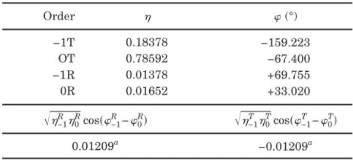
Table 1 shows the results of the diffraction efficiencies and phases of all the existing diffracted orders as well as the values of both product terms in Eq. (12) for a grating
of period 0.4m and depth 0.2m. For this grating there
are only two transmitted diffracted orders and two re-flected diffracted orders; thus both products must be equal with opposite sign. Table 2 shows the corresponding
results for a grating of period 0.6m and depth 0.5m.
For this grating there are four transmitted diffracted or-ders and two reflected diffracted oror-ders; thus the sum of the three product terms must equal zero. Table 3 shows
the results for a grating of period 0.8m and depth
0.6m. For this grating there are six transmitted
dif-fracted orders and four reflected difdif-fracted orders; thus the sum of the five product terms must equal zero.
Note that, independent of the period (number of orders) and depth of the grating, the sum of the products remains near zero, confirming the validity of the constraint stated in Eq. (12) and that both amplitude and phase calculated
by the employed method9are credible.
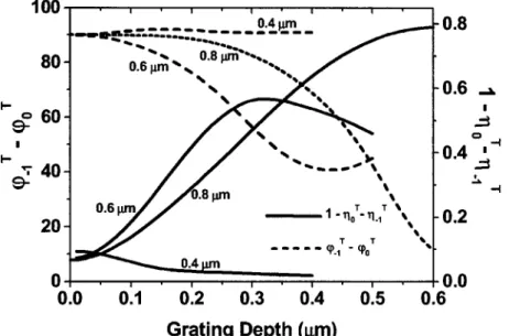
Figure 2 shows a graph of the phase difference between the minus first diffracted order and the zeroth diffracted
order by transmission共−1T −0T兲 for sinusoidal surface
re-lief gratings with three different periods (0.4, 0.6, and
0.8m) as a function of the grating depth. Note that for
the grating period of 0.4m the phase difference remains
close to the/ 2 value, as expected from Eq. (15). In the
same figure is shown (right axis) a graph of the sum of the efficiencies of all remaining diffracted orders (excluding the minus first and zeroth orders) as a function of the grating depth. We can observe that the deviation of the
phase difference 共−1T−0T兲 from the / 2 value with the
grating depth starts when the sum of the diffraction effi-ciencies of the remaining diffracted orders increases, and it occurs in the same sequence of grating period.
4. EXPERIMENTAL RESULTS
Using a method proposed in a previous paper,10we
mea-sured the phase difference between the minus first and the zeroth transmitted diffracted orders of surface relief gratings at Littrow mounting. During the measurement a
Table 1. Diffraction Efficiencies, Phases, and Product Terms for a Sinusoidal Grating of
Period 0.4m and Depth 0.2m
Order (°)
−1T 0.18378 −159.223
OT 0.78592 −67.400
−1R 0.01378 +69.755
0R 0.01652 +33.020
冑
−1R0Rcos共−1R−0R兲冑
−1T0Tcos共−1T−0T兲0.01209a −0.01209a
a
Value of product terms in Eq.共13兲calculated using data from upper part of table.
Table 2. Diffraction Efficiencies, Phases, and Product Terms for a Sinusoidal Grating of
Period 0.6m and Depth 0.5m
Order (°)
2T 0.12465 −114.561
−1T 0.33247 101.015
0T 0.20777 146.126
1T 0.31934 81.953
−1R 0.00583 135.301
0R 0.00994 94.930
冑
−1R0Rcos共−1R−0R兲冑
−1T0Tcos共−1T−0T兲冑
−2T1Tcos共−2T−1T兲0.00580a 0.18549a −0.19129a
a
Value of product terms in Eq.共12兲calculated using data from upper part of table.
Table 3. Diffraction Efficiencies, Phases, and Product Terms for a Sinusoidal Grating of
Period 0.8m and Depth 0.6m
Order (°)
−3T 0.03598 −12.010
−2T 0.10664 −108.241
−1T 0.14687 75.474
0T 0.06330 87.029
1T 0.51361 −6.953
2T 0.11579 −160.566
−2R 0.00606 −40.757
−1R 0.00079 −43.394
0R 0.00230 +9.918
1R 0.00868 −80.105
冑
−3T2Tcos共−3T−2T兲冑
−2T1Tcos共−2T−1T兲冑
−1T0Tcos共−1T−0T兲−0.05507a −0.04581 0.09446
冑
−2R1Rcos共−2R−1R兲冑
−1R0Rcos共−1R−0R兲0.00561 0.00081
a
grating recorded in a photoresist film of AZ 1518, coated on a glass substrate, is repositioned in the same setup in
which it was recorded.10 In order to avoid the effects of
the reflection at the rear side of the substrate, the glass substrate was index matched with a glass prism.
The accuracy of the measurement is dependent on the accomplishment of a high-precision repositioning, when a
moiré-like pattern should be formed.10The experimental
measurements of the phase difference between the
nega-tive first and the zeroth transmitted diffracted orders
共−1T −0T兲 for holographic surface relief gratings of period
0.8m and different depths are shown in Fig. 3. For
com-parison, in the same figure are shown the theoretical
ex-pected curves for phase difference共−1T −0T兲for three
dif-ferent grating profiles: sinusoidal, lamellar, and
triangular. Note that despite the large experimental er-rors, the experimental measurements of the phase
differ-ence 共−1T−0T兲 follow the expected theoretical curve for
Fig. 2. Phase difference between the minus first and the zeroth diffracted orders by transmission共−1T−0T兲as a function of the grating
depth for sinusoidal relief gratings in photoresist共n= 1.645兲for the TE polarization and= 457.9 nm and for three different grating periods 0.4, 0.6, and 0.8m. In the same graphic (right scale) is shown the sum of the diffraction efficiencies of all other existing dif-fracted orders (excluding the minus first and zeroth).
Fig. 3. Experimental results for the phase difference between the minus first and zeroth transmitted diffracted orders共−1T−
0
T兲for a
holographic surface relief photoresist grating of period 0.8m with different grating depth. In the same figure are shown the theoretical phase difference between the first and zeroth transmitted diffracted orders共−1T−0T兲as a function of the grating depth for three different
the sinusoidal profile. Some experimental points deviate from the curve corresponding to the sinusoidal grating profile, approaching the curve corresponding to the lamel-lar grating profile. An analysis of the grating profiles of such samples by scanning electron microscopy confirm the changes in the sinusoidal profile, as can be seen in the inset photograph.
The departure of the phase difference 共−1T −0T兲 from
the/ 2 value as a function of the grating depth is
differ-ent for the three differdiffer-ent grating profiles. This occurs as a result of the different increase, in energy of the remain-ing diffraction orders as the gratremain-ing depth increases, for the different grating profiles. As the sum of the efficien-cies of the remaining diffracted orders for a lamellar grat-ing increases more rapidly with the depth than that for a
sinusoidal grating profile, the departure from the / 2
value also occurs more rapidly. For the same reason the opposite behavior should be expected for the triangular-shaped grating.
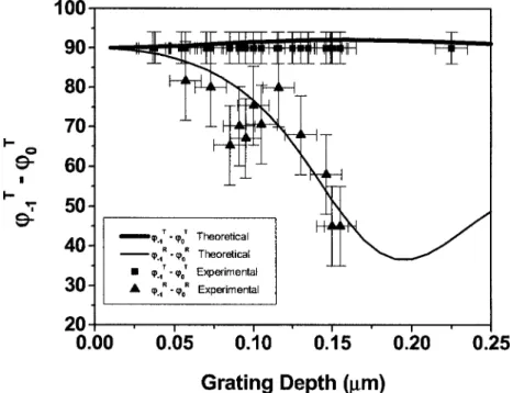
Figure 4 shows the experimental measurement of the
phase difference 共−1T −0T兲 and 共−1R −0R兲 for photoresist
gratings of period 0.4m and different depths. The
squares show the measurement for the transmitted
or-ders共−1T −0T兲, and the triangles show the phase
differ-ence共−1R −0R兲measured for the reflected orders.
The measurement of the phase differences between the reflected orders presents a larger error bar as well as a larger dispersion compared with the transmitted orders, because the same mismatch in the grating replacement produces a greater distortion in the reflected wavefronts than in the transmitted ones. In addition, the reflection at the photoresist–glass interface introduces an error in the phase measurements that can be neglected for the trans-mitted orders, because their intensities are higher.
Note that for the transmitted orders the phase
differ-ence remains close to/ 2 while the phase difference
be-tween the reflected orders does not. This occurs because for this period there are only two diffracted transmitted orders and two reflected diffracted orders, and the diffrac-tion efficiencies of the reflected orders are negligible in comparison with those of the transmitted orders. Thus from Eq. (15) the phase difference between the two more
efficient orders must be close to/ 2.
5. CONCLUSIONS
Using only energy conservation and the symmetry prop-erties of the grating, we derived a general constraint re-lating the phases and amplitudes of the diffracted orders for a lossless symmetrical grating at Littrow mounting. Although this same constraint can be derived from a gen-eral treatment of the diffraction problem by using reci-procity, energy conservation, and the symmetry proper-ties of a grating, this formulation gives a physical insight for the phases allowing one to predict the phase-difference behavior as a function of the grating param-eters (such as period, depth, and material).
The numerical verification of this phase constraint [Eq. (12)] allows checking the confidence of the calculated am-plitude and phase values of the diffracted orders as well as the method of calculation. The experimental measure-ments of the phase differences between the minus first and zeroth diffracted orders demonstrate that both the behavior expected by the phase constraint and the theo-retical calculation of the phases are correct.
ACKNOWLEDGMENTS
We acknowledge the financial support of the Fundação de Amparo a Pesquisa do Estado de São Paulo (FAPESP) and Conselho Nacional de Pesquisa (CNPq).
Fig. 4. Experimental measurements and corresponding theoretical curves for the phase difference between the minus first and zeroth diffracted orders共−1T−0T兲by transmission and by reflection共−1R−0R兲for a holographic surface relief photoresist grating共n= 1.645兲of
Corresponding author L. Cescato’s e-mail address is [email protected].
REFERENCES
1. H. Kikuta, Y. Ohira, and K. Ywata, “Achromatic quarter-wave plates using the dispersion of form birefringence,” Appl. Opt.36, 1566–1572 (1997).
2. V. Kettunen and F. Wyrowski, “Reflection mode phase retardation by dielectric gratings,” Opt. Commun. 158, 41–44 (1998).
3. L. C. Botten, “A new formalism for transmission gratings,” Opt. Acta25, 481–499 (1978).
4. L. C. Botten, J. L. Adams, R. C. McPhedran, and G. H. Derrick, “Symmetry properties of lossless diffraction gratings,” J. Opt.11, 43–52 (1980).
5. D. L. Staebler and J. J. Amodei, “Coupled-wave analysis of holographic storage in LiNbO3,” J. Appl. Phys. 43,
1042–1049 (1972).
6. J. L. Uretsky, “The scattering of plane waves from periodic surfaces,” Ann. Phys.33, 400–427 (1965).
7. H. Kogelnik, “Coupled wave theory for thick hologram gratings,” Bell Syst. Tech. J.48, 2909–2947 (1969). 8. J. W. Goodmam, Introduction to Fourier Optics, 2nd ed.
(McGraw-Hill, 1996).
9. L. Li, J. Chandezon, G. Granet, and F.-P. Plumey, “Rigorous and efficient grating-analysis method made easy for optical engineers,” Appl. Opt.38, 304–313 (1999).