Materials Research. 2010; 13(1): 21-24 © 2010
*e-mail: [email protected]
The Effect of Weld Geometry and Post-Weld Heat Treatment on the Corrosion
Behaviour of Austenitic Stainless Steel Immersed in 1.0 M NaCl Solution
Oladele Isiaka Oluwole, Joseph Ajibade Omotoyinbo, Akinwekomi Akeem Damilola*
Department of Metallurgical and Materials Engineering,
Federal University of Technology, Akure Ondo State, Nigeria
Received: January 22, 2009; Revised: May 19, 2009
The variation of welding parameters such as weld geometry and post-weld heat treatment on the corrosion behaviour of austenitic stainless steel in a saline environment of 1.0 M NaCl was investigated in this work. Rods of austenitic stainless steel of known chemical composition were prepared and welded using electric arc welding technique varying the aforementioned parameters. Thereafter, samples for the corrosion behaviour investigation were then cut out of the welded rods. The analysis of the experimental data revealed that the best weld geometry was chamfered and a post-weld heat treatment carried out at temperatures in excess of 700 °C followed by air cooling improves the quality of a weld.
Keywords: welding parameters, weld geometry, post-weld heat treatment, austenitic stainless steel
1. Introduction
Austenitic stainless steels are essentially iron-chromium-nickel ternary alloys containing about 16 to 25% Cr and 7 to 20% Ni. These alloys are called austenitic since their structure remains austenitic at all normal heat treating temperatures. The presence of the nickel which has an FCC crystal structure enables the FCC structure to be retained at room temperature. The high formability of the austenitic stainless steels is due to its FCC crystal structure12. Austenitic stainless
steels posses’ good mechanical properties and corrosion resistance which account for its application in many equipment and environ-ments like low and high pressure boilers and vessels, fossil-fired power plants, flue gas desulphurisation equipment, food processing plants and surgical implants.
Arc welding and resistance (seam) welding are the welding methods preferred for high alloy, iron-base alloys (stainless steels and high temperature steels). Agarwal2 stated that one of the most
employed methods of fabricating austenitic stainless steels com-ponents is by welding which requires the application of heat and or pressure. A major consideration in these materials is the loss of alloying elements during the welding cycle, particularly chromium, which has both a high vapour pressure and a high heat of formation of the oxide. Segregation of alloying additions during solidification of the weld metal leads to compositional changes and microstructural inhomogeneity. Carbide precipitation has a major effect on the corro-sion susceptibility of high alloy steels and makes some compositions particularly susceptible to stress corrosion cracking. In welding, two components are joined by heating the region at the interface above the melting point of one or other of the components. Welding is a term to describe bonding by localized melting.
Austenitic stainless steels normally have better corrosion resist-ance than ferrite and martensitic ones because the carbides can be retained in solid solution by rapid cooling from high temperatures. However, if these alloys are to be welded or slowly cooled from high temperatures through the 870 to 600 °C range, they can become susceptible to intergranular corrosion, because chromium-containing carbides precipitate at the grain boundaries. This difficulty can be
circumvented to some degree either by lowering the maximum car-bon content in the alloy to about 0.03% C or by adding an alloying element such as columbium (niobium) to combine with the carbon in the alloy12.
Any weld design must aim at ensuring the integrity of the weld and, effectively the same thing; minimize the effects of welding defects. There are two major considerations. Firstly, the control of dimensions and thermal history of the molten metal in the weld pool. Secondly, the analysis of the geometrical constraints imposed by the system and the effect of these constraints on the development of residual stresses during the welding cycle.
Some high performance, specialty steels depend on the precipita-tion of intermetallic phases to attain their high strength and toughness, and several of these compositions can be successfully heat treated after welding. Heat treatable, welded steels do not contain carbon, which would be deleterious both to the weldability and to the heat treatment response5.
The effect of poor welded stainless steels joint can be very catastrophic in service. Typical occurrence are; The collapse of a grade 304 stainless steel pipe meant for conveying glucose solu-tion on the 4th of May, 1986, in Illinois, USA, caused by corrosion
cracking8 and, similar event was also reported by Chamberlain and
Trethewey13, when the Point Pleasant Bridge in Ohio made in part
with type 316 grade collapsed killing 46 people. It was discovered that the cause of the failure was a stress corrosion cracking 2.5 mm deep in the welded head end of the eye bar.
22 Oladele et al. Materials Research
model AVD890F series was used for measuring this parameter using a zinc rod as the reference electrode. The values obtained were then converted to Saturated Calomel Electrode (SCE) values using the formula obtained from Hilbert6.
Electrode Potential mV (SCE) = [ EZn – 1030] mV (1)
where:
Ezn = electrode potential values using high purity zinc as a refer-ence electrode
3.2. Corrosion rate estimation from weight loss
measurement
The weight loss for each of the samples was obtained using an electronic weighing balance model Mettler AE160 g. After taking the initial weight of the samples, they were immersed in 1.0 M NaCl solu-tion. The samples are withdrawn at every five days intervals, washed with distilled water and dried with cotton wool before the weight is taken. This was carried out for sixty five days. The corrosion rate was deduced using the formula;
Corrosion Rate = W/ A (t /365) (mg/cm2/year) (2)
where
W = Weight Loss, in mg A = Area of Sample ( ϖd2/4)
d = diameter of sample (12 mm)
t/365 = exposure time in days extrapolated to a year
4. Results and Discussion
4.1. Effect of weld geometry on the corrosion behaviour of
austenitic stainless steel in 1.0 M NaCl solution
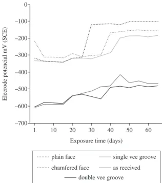
Figures 1 and 2 show the response of the weld geometry of the austenitic stainless steel in 1.0 M NaCl solution. As shown in Figure 1, the as-received sample followed by the chamfered and single vee grooves samples have higher electrode potentials compared to the plain and double vee grooves samples. The as-received sample and the single vee groove have their electrode potentials increased in a slow manner within the first 25th days (–318 to –315 mV) and (–331 to
–315 mV) respectively after which they are separated. While the as-received sample experiences a sharp increase (–315 to –120 mV) within five days that was maintain till the last day of the research as (–103 mV), the single vee groove still continue in its manner of in-crease until the 40th day where it experiences a sharp increase (–286 to
–198 mV) within five days. This was maintained till the last day of the research as (–185 mV). The chamfered face sample experiences a sharp decrease in the electrode potential within the first five days of the research (–216 to –313 mV) after which it begins to increases slowly in a fluctuating manner till the 35th day and there experiences
a sharp increase (–298 to –167 mV) that was maintained till the last day of the research as (–154 mV). It was clearly observed that the electrode potentials of the as-received followed by the chamfered face welded sample and of the single vee groove welded sample showed a higher level of passivation and immunity than the plain face and double vee welded samples.
2. Materials and Methods
2.1. Materials
The materials used for this research work include a hot rolled austenitic stainless steel rod of diameter 12 mm and length 3.6 m. The chemical composition was given in Table 1 below. Hand hack saw, hand file, wire brush G-clamp, electric arc welding machine, electrical laboratory polishing machine, electrical Full-Muffle fur-nace, stainless steel core electrode fluxed with Mo and Mn, (E317M) and 1.0 M NaCl solution.
2.2. Methods
2.2.1. Preparation of samples for welding
The austenitic stainless steel rod was cut into lengths of 55 mm with hand hack saw which were used for the experimental work. This was followed by the edge design. The edges that were prepared for the weld geometry test are single vee groove, double vee groove, plain face and chamfered face. Post-weld heat treatment test samples were also prepared with single vee groove edge.
2.2.2. Welding process
Electric arc welding process was used for the welding operations at a constant current of 160 A. Before the welding operations, the prepared sample edges were set together with a little root gap be-tween them and were clamped into position with G-clamp to prevent movement and mass effect during welding and cooling respectively. During welding, the electrode was held at an angle and ran through the edges until there was penetration and development of weld pool to fill the gap. After welding, iron brush was used to clean off the slag covering as the samples are allowed to air-cool. Two samples each were welded for each of the test samples from where the sample with the best joint was selected through visual examination.
2.2.3. Post-weld heat treatment
Post-weld heat treatment operations were carried out on the pre-pared samples at the predetermined temperatures of 500, 600, 700 and 800 °C respectively with Electrical Full-Muffle furnace. These samples were soaked for thirty minutes and air cooled.
2.2.4 Preparation of samples for corrosion test
Before the samples were immersed in the alkaline solution, scales that were formed on both the welded samples and that of the heat treated samples were removed with hand file followed by grinding and polishing using an electrical laboratory polishing machine. The samples were later washed with distilled water and dried.
3. Corrosion Behaviour Test
3.1. Electrode potential measurement
Prepared samples from both the weld geometry and post-weld heat treatment were completely immersed in 300 mL containers of 1.0 M NaCl solution. The electrode potential was taken at intervals of five days for a period of sixty five days. A digital multimeter
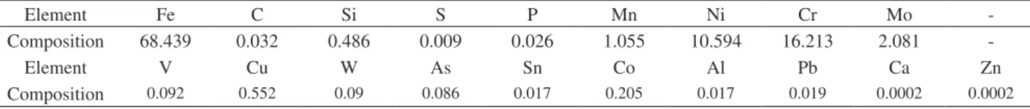
Table 1. Chemical composition of austenitic stainless steel used in wt. (%)
Element Fe C Si S P Mn Ni Cr Mo
-Composition 68.439 0.032 0.486 0.009 0.026 1.055 10.594 16.213 2.081
-Element V Cu W As Sn Co Al Pb Ca Zn
2010; 13(1)
The Effect of Weld Geometry and Post-Weld Heat Treatment on the Corrosion
Behaviour of Austenitic Stainless Steel Immersed in 1.0 M NaCl Solution 23
difference in the corrosion rates of all the samples till the last day of the research. The result shows that the as-received sample followed by the chamfered face sample has the highest resistance to corrosion in the saline medium as shown in Figure 2. This result confirms the result from the electrode potential (Figure 1) from where it was ob-served that the as-received sample followed by the chamfered sample has the highest passivation and immunity potentials.
From the result obtained, it can be stated that distortion may result from mechanical working due to the realignment of the grains near the points of machining during surface preparation9. Ulick11
also explained that the stress corrosion cracking can occur as a result of frettage introduced by the machining of the surface for welding. In light of these findings, the double vee groove sample may have experienced much damage of the microstructure close the weld zone, hence, more deterioration during immersion.
The unprepared plain faced sample (12 mm thick) also experi-enced a higher corrosion rate because of its thickness. This follows from the works of Khana9 that edge to be welded if more than 3.2 mm
thick needed some edge preparation, hence the deterioration of the plain faced sample due to inadequate penetration of the weld pool.
4.2. Effect of post-weld heat treatment on the corrosion
behaviour of austenitic stainless steel in 1.0 M NaCl
solution
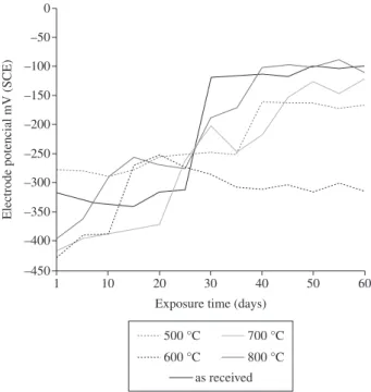
Figures 3 and 4 clearly illustrate the response of the post-weld heat treatment of the austenitic stainless steel in 1.0 M NaCl solution. From Figure 3, the electrode potential of samples heat treated at 800, 700 and 600 °C increases till the 15th, 20th and 10th days (–396 to
–257 mV), (–416 to –372 mV) and (–428 to –388 mV) respectively before they started to experience different types of increase in a fluctuating manners. While sample heat treated at 800 °C experiences a sharp decrease after the 15th day within the next ten days (–257 to
–276 mV), it begins to experiences a sharp increase in a fluctuating manner till the last day of the research; sample heat treated at 700 °C experiences a sharp increase after the 20th day within the next ten days
(–372 to –202 mV) after which it begins to experiences an increase in a fluctuating manner after initial sharp decrease from the point (30th day) till the last day of the research; the sample heat treated at
600 °C experiences a sharp increase after the 10th day within the next
ten days (–388 to –252 mV) after which it begins to experiences a decrease in a fluctuating manner till the last day of the research . On the other hand, the as-received sample and the sample heat treated at 500 °C first experiences a decrease till the 15th day before they begin to
increase in a fluctuating manner. The as-received sample experiences a sharp increase within the 25th and the 30th day (–315 to –120 mV).
From the result, it was clearly observed that the electrode potentials of the sample heat treated at 800 °C followed by the as-received and sample heat treated at 700 °C showed a higher level of passivation and immunity than the samples heat treated at 600 and 500 °C.
The corrosion rates for all the samples decreased rapidly from the first day to the 15th day except the sample that was heat treated
at 600 °C that experiences such rate till the 20th day. Within those
days, sample heat treated at 600°C (23.00-4.5 mg/cm2/year)
fol-lowed by sample heat treated at 500 °C (18.00-3.00 mg/cm2/year)
have the highest corrosion rates while the sample heat treated at 800 °C (10.30- 0.80mg/ cm2/ year) followed by as-received sample
(15.20- 1.20 mg/cm2/year) and sample heat treated at 700 °C
(12.60- 1.20 mg/cm2/year) have the least corrosion rates. After this
days, the corrosion rates still continued but in a slower and fluctuat-ing manner till 30th day after which there is no appreciable
differ-ence in the corrosion rates of all the samples except that of sample heat treated at 600 °C that was still higher than others till the last Figure 1. Plot of Electrode Potential vs. Exposure Time of Austenitic Stainless
Steel Welded at various Weld Geometry.
Figure 2. Plot of corrosion rate vs. exposure time of austenitic stainless steel welded at various weld geometry.
The corrosion rates for all the samples decreased rapidly from the first day to the 15th day. Within those days, double vee groove
sample (38.00-5.20 mg/cm2/year) followed by plain face sample
(36.00-5.60 mg/cm2/year) have the highest corrosion rates while the
as-received sample (15.20-1.20 mg/cm2/year) followed by the
cham-fered face sample (22.30-3.60 mg/cm2/year) have the least corrosion
24 Oladele et al. Materials Research
followed by as-received sample and sample heat treated at 700 °C have the highest passivation and immunity potentials.
According to Honeycomb7, the solubility limit of carbon is about
0.05% at about 800 °C, rising to 0.5% at about 1100 °C, therefore it can be inferred that the higher the temperature of annealing the greater the tendency of the material to display a higher rate of corro-sion resistance except in the range 500-600 °C. Therefore the solution treatment between 800 and 1100 °C will take almost all the carbon into solution and a rapid rate of cooling from this range will give a supersaturated austenitic solid solution at room temperature. The 800°C sample maintained the highest level of passivity throughout the period of immersion followed by a high level of immunity which may have been due to the formation of adequate protective film as observed by Ulick11.
5. Conclusion
This research work has shown that welding variables such as weld geometry and post-weld heat treatment have effects on the service, functionality and service behaviour of austenitic stainless steel. The heat affected zone is the weakest part of a weld as corro-sion is majorly propagated in the zone. The following appreciable conclusions can be reached:
1) Results from the weld geometry variation showed that the chamfered edge preparation is the best for welding. This was closely followed by the sample with the single vee groove.
2) Temperatures range of 700 and 800 °C are suiTable for the heat treatment of welded samples.
References
1. American Welding Society - AWS. Welding handbook. New York: Macmillan Press; 1988. p. 20-22. (section 1)
2. Agarwal RL. Welding engineering: a textbook for engineering students. 4 ed. Delhi: Kanaa Publishers; 1992.
3. Chen CL. Austenitic stainless steel chemical composition manual; 2002. p. 1-2. Available from: www.ms2.hinet\\austeniticstainless.steel.chemical. composition.htm.
4. Dave Wright. Stainless steel, electronic handbook. Dave Wright; 2002. p. 1-2. Available from: www.davewrightwelding.org\stainless.steel.htm.
5. Brandon DD and Kaplan WD. Joining process: an introduction. England: John Wiley and Sons; 1997. p. 17-18.
6. Hilbert BD and James AM. Dictionary of electrochemistry. London: Macmillan Press; 1984.
7. Honeycomb RKW and Bhadeshia HKDH. Steels: microstructure and properties, metals and materials series. 2 ed. London: Edward Arnold; 1995.
8. James GK. Chronology of corrosion disasters. New York: American Metal Society (AMS) Handbook; 2002. (vol. 5)
9. Khanaa OP. A textbook on welding technology for engineering students. Delhi: Dhampa Rai & Sons; 1990.
10. Llewellyn DT. Steels metallurgy and application. Oxford: Heinnemann-Butterwirths; 1992.
11. Ulick ER. The corrosion and oxidation of metals. London: Evans Publication; 1976. (supplementary volume)
12. Willian FS. Principle of materials science and engineering. 2 ed. New York: McGraw-Hill Publishing Company; 1990. p. 534-535.
Figure 3. Plot of electrode potential vs. exposure time of austenitic stainless steel welded at various post-weld heat treatments.
Figure 4. Plot of corrosion rate vs. exposure time of austenitic stainless steel at various post-weld heat treatments.