NUMERICAL MODELING OF HEAT
TRANSFER AND FLUID FLOW IN
KEYHOLE PLASMA ARC WELDING OF
DISSIMILAR STEEL JOINTS
M. A. Daha*
Production Engineering Department, Alexandria University, Alexandria, 21544, Egypt
m_daha@hotmail.com
G. A. Nassef
Production Engineering Department, Alexandria University, Alexandria, 21544, Egypt
galalnassef@gmail.com
I. A. Abdallah
Production Engineering Department, Alexandria University, Alexandria, 21544, Egypt
ismailewa_alex@yahoo.com Abstract :
The evolution of temperature profiles and weld pool geometry during dissimilar welding between 2205 duplex stainless steel and A36 low carbon steel using keyhole plasma arc welding has been simulated using a three dimensional numerical heat transfer and fluid flow model. An adaptive heat source is proposed as a heat source model for performing a non-linear transient thermal analysis, based on the configuration feature of keyhole plasma arc welds. Temperature profiles and solidified weld pool geometry are presented for three different welding heat input. The reversed bugle shape parameters (width of fusion zone at both top and bottom surfaces) of the weld pool geometry features for a dissimilar 2205–A36 weld joint are summarized to successfully explain the observations. The model was also applied to keyhole plasma welding of 6.8 mm thick similar 2205 duplex stainless steel joint for validation. The simulation results were compared with independently obtained experimental data and good agreements have been obtained.
Keywords: dissimilar metals, finite element analysis, weld geometry, temperature field.
1. Introduction
Duplex stainless steels (DSSs) are gaining extensively increased applications as structural materials in various industrial sectors, such as offshore construction, chemical, petrochemical, pulp and paper, power generation, desalination, and oil and gas. DSSs have superior mechanical properties and corrosion characteristics relative to other stainless steels and structural steels. Recently, in view of increasing applications of DSSs, it is important to have a better understanding of the issues associated with welds to dissimilar metals.
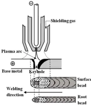
Fig. 1. Keyhole plasma arc welding technique
The keyhole PAW offers significant advantages over conventional tungsten inert gas (TIG) welding in terms of penetration depth, joint preparation and thermal distortion. In addition, the keyhole PAW can be used for butt welds from approximately 3 mm up to 7-8 mm thick with a single pass; by comparison, the TIG method is only suitable for butt welds up to approximately 3-4mm thick [1]. These are some of the reasons justifying the substitution of TIG welding with plasma keyhole welding. The temperature profile around the keyhole and the weld pool has a great influence on the formation and stability of the keyhole. Therefore, it is of great significance to model and simulate the temperature distribution, weld thermal cycles ,and weld pool geometry in the keyhole PAW process for dissimilar DSSs joints.
2. State of the Art
In recent years, plasma welding of duplex stainless steels has become of great interest in the industry; however, the research woks in this field are relatively limited. Urena et al. [2] have determined the optimum welding conditions, in terms of heat input, microstructure, and hardness, for plasma welding of 2205 DSS that is 3 mm thick. Zheng et al. [3] have investigated the effects of a dual-torch technique using plasma welding followed by TIG welding on the microstructure and corrosion properties of 2205 DSS. Taban [4] investigated the effects of plasma welding and of combined plasma and TIG welding on the microstructure and toughness of SAF 2205 DSS. In further work, Taban [5] investigated the effect of plasma welding on the toughness of UNS 32750 super duplex stainless steel. Migiakis et al. [6] focused on plasma keyhole welding of UNS S32760 (Zeron 100) super duplex stainless steel and studied the microstructure, tensile strength, and impact toughness of the weldments. Barnhouse and Lippold [7] have investigated the effect of two filler metals using TIG welding on the ferrite number of the dissimilar DSS SAF 2205/carbon steel ASTM-A36 weld joint. Mendoza et al. [8] studied the effects of the welding designs and the filler metal on the mechanical properties and microstructural changes of dissimilar super-DSS 2507/API X52 weld joints.
Although many studies have been conducted for welding of 2205 duplex stainless steel, most of the results were concerned with the microstructure and corrosion properties of the welded joints. In addition, research has been limited to experimental work. There is a paucity of reliable information about thermal cycles and temperature distributions in dissimilar 2205 duplex stainless steel weldments. No attempt has been made yet to simulate three dimensional-dimensional finite element model for keyhole PAW of dissimilar 2205–A36 joint. In this paper, dynamic evolution of geometrical shape, the dimensions and fluid flow of the molten pool, temperature distributions and thermal cycles, and the keyhole of dissimilar 2205–A36 joint have been simulated via the three-dimensional thermal keyhole PAW finite element model based on the adaptive heat source model proposed by Wu et al. [12]. In addition, the developed thermal model has been experimentally verified by comparing the predicted weld pool geometry and size obtained from the thermal analysis with the experimental results.
3. Finite Element Analysis
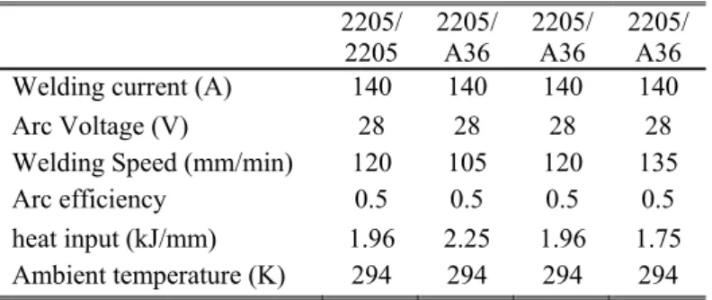
In the current investigation, the temperature field and the weld pool geometry during keyhole PAW of a 2205– A36 plate was simulated by a full three-dimensional uncoupled thermal finite element formulation that was implemented in ABAQUS® code [14]. For accurate simulation of the temperature history, it is important to implement an additional user-subroutine as a FORTRAN code. The simulated welding parameters are given in Table 1.
Table 1. Welding conditions for 6.8 mm thick similar and dissimilar plates
2205/ 2205
2205/ A36
2205/ A36
2205/ A36 Welding current (A) 140 140 140 140
Arc Voltage (V) 28 28 28 28
Welding Speed (mm/min) 120 105 120 135
Arc efficiency 0.5 0.5 0.5 0.5
heat input (kJ/mm) 1.96 2.25 1.96 1.75
Ambient temperature (K) 294 294 294 294
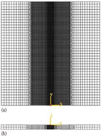
Fig. 2. 3D symmetrical graded finite element mesh: (a) Top view; (b) Side view
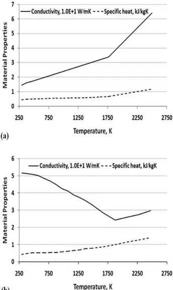
The chemical composition of the base metals used in this study is given in Table 2. Furthermore, Temperature-dependent thermo physical properties, i.e., the thermal conductivity and specific heat, are plotted in Fig. 3. Other properties used in the analysis are summarized in Table 3.
Table 2. Chemical composition of the base metals (in wt%)
Cr Mo Ni C Si Mn P S Fe
2205 22.55 3.13 5.64 0.012 0.46 1.48 0.037 0.001 Balance A36 – – – 0.088 0.236 0.627 0.005 0.025 Balance
Table 3. Material properties for 2205 DSS and A36 used in calculations
Property
2205 A36 Value
Latent heat of fusion (kJ/kg) 500 247 Liquidus Temperature (K) 1773 1817 Solidus temperature (K) 1658 1738
Density of metal (kg/m3) 7860 7760
Fig. 3. Thermo-physical material properties for: (a) 2205 DSS and (b) A36
In heat transfer theory, taking into account the energy and ignoring stress, strain, and displacement. The temperature T of the weld plate is a function of time (t) and the spatial coordinates (x, y, z), and it is calculated by solving the following transient non-linear heat transfer governing differential equation:
t T c q z T z k z y T y k y x T x k x (1)
Here, kx, ky and kz are the thermal conductivities in the x, y, and z directions, respectively; ρ is the density; c is
the specific heat of the material; and q is the internal heat source rate. To solve the above differential equation, initial and boundary conditions must be specified. If T0 is the atmospheric temperature or room temperature, the initial condition is:
x y z
T
x y z
T , , ,0 0 , , (2)
The thermal boundary conditions include the radiation and convection heat losses to the environment from the outer surface are assumed and defined by:
0
4 04
0 T T T T h q n Twhere Kn is the thermal conductivity normal to the surface, σ = 5.67×10⁻⁸ (W m-2 K-4)is the Stefan Boltzmann
constant. For the radiative and convective boundary conditions, a combined heat transfer coefficient was calculated by Vinokurov's empirical relationship [10, 15, and 16]:
61 1 3 10 41
2. εT .
h (4)
where ε is the emissivity and T is the temperature in K.
To account for the heat transfer effects due to fluid flow in the weld pool, an artificial increase in the thermal conductivity above the melting temperature is used [17-22]. In this study, it was assumed that the value of the thermal conductivity is approximately three times as large as that at room temperature when the temperature is higher than the melting point. The thermal effects due to solidification of the weld pool are modeled by taking into account the latent heat for fusion. The latent heat is considered between the solidus temperature and the liquidus temperature.
4. Heat Source Model
A variety of heat source models can be used to simulate the heat input from the welding torch, e.g., triangular, conical, double-ellipsoidal, and adaptive heat sources. The choice of heat source model depends upon the type of welding process. In this study, for keyhole PAW, the heat from the moving welding arc is modeled by an adaptive heat source presented by Wu et al. [12] to match the weld pool configuration feature of keyhole PAW welds. The adaptive heat source model combines a double-ellipsoidal volumetric heat source acts at the upper part of the workpiece and a cylindrical volumetric heat source exerts at the lower part of the workpiece. The net heat input q to the workpiece from the keyhole PAW arc is described as follows:
IV
q (5)
where η is the arc efficiency, I is the electric current, and V is the voltage. The power of the combined heat source, qdv and qcv, describing the power inside the double-ellipsoidal volumetric heat source and the cylindrical
volumetric heat source, can be expressed as: q 1 β dv
q (6)
q 2 β cv
q (7)
q 2 β 1 β cv q dv qq (8)
where β1 and β2 are the power distribution factors which give the fraction of heat deposited in the upper and
lower parts of the workpiece, respectively. If z < c, y < 0,
2 2 2 1 2 2 2 2 1 1 1 1 V c 3z b 3y a 3x exp b b b c ab π π q β 3 12 z y, x, Q (9)If z < c, y ≥ 0,
2 22
2 2 2 2 2 1 2 2 1 V c 3z b 3y a 3x exp b b b c ab π π q β 3 12 z y, x, Q (10)
If z ≥ c,
where a, b1, b2, and c are the characteristics parameters of the double ellipsoidal volumetric heat source, m =
r1/H, r1 is the radius of the cylindrical region, and H is the height of the cylindrical heat source. r2 = x2 + y2, H =
L - c, and L is the workpiece thickness. The parameters β1, β2, a, b1, b2, c, and r1 of the heat source can be
adjusted to create a desired melted zone.
Using equations (9, 10, and 11), a user subroutine DFLUX has been written in FORTRAN to define the non-uniform distributed flux as a function of time, position, and temperature during the heat transfer analysis. The user subroutine DFLUX has been embedded into ABAQUS/Standard to automatically detect the position of the welding pool and to calculate the volumetric heat flux, then to assign it to the correct elements of the welding plates while the torch is moving through.
5. Verification of the Finite Element Model
To confirm the accuracy of the thermal finite element analysis method used in the present investigation, a single-pass keyhole PAW experiments were conducted on a 2205 DSS plate with a thickness of 6.8 mm. Straight plate edges perpendicular to the plate surface have been prepared. The welding parameters chosen for the experiments were as follows: V = 28 Volts, I = 140 A, η = 0.50 and a welding speed = 0.002 mm/sec. PAW
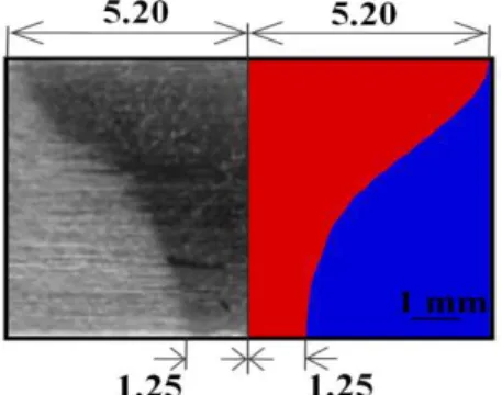
in keyhole mode was accomplished without any filler metal and by using direct current electrode negative (DCEN) polarity. The results obtained from the thermal analysis were compared with the experimental results. Figure 4 shows the typical weld fusion zone shape and size obtained from the experiments and the corresponding weld fusion zone shape and size obtained from the simulation model. It can be observed that the predicted weld fusion zone geometry and width at both top and bottom surfaces show good agreement with those measured experimentally.
Fig. 4. Comparison of the weld fusion zone: experiment vs. simulation
6. Results and Discussion
6.1.Temperature Distribution
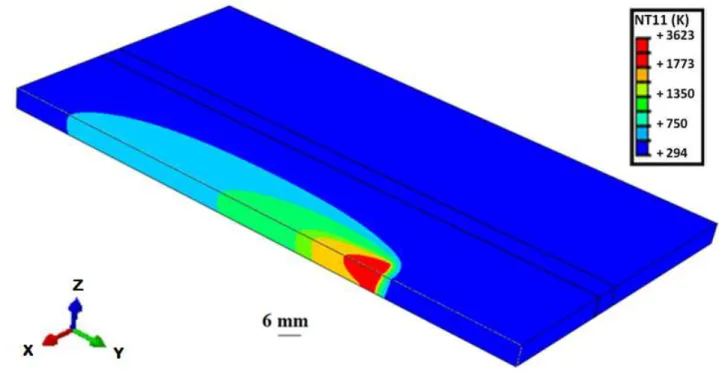
Figure 5 shows the temperature distribution of the 6.8 mm thick plate when the keyhole PAW torch passes through the whole plate in the (y-direction). It is noticed that all of the material with in the fusion zone rises in temperature above the melting point, reaching 3623 K for a heat input of 1.96 kJ/mm. This high temperature is the main attribute in the formation of the keyhole, converting liquid to vapor. Figure 6 shows the evolution of the weld pool as the keyhole PAW takes place. The temperature contours indicate the pattern of heat flow in the weldment. These contours are drawn for V = 28 Volts, I = 140 A, η = 0.50, and a welding speed = 0.002
mm/sec. To observe the molten-zone growth, the isotherm corresponding to the liquidus temperature (1773 K) is plotted and examined. The fully developed fusion zone is completely formed at (t = to + 1.15 S), has the shape
Fig. 5. Three-dimensional temperature distribution in the 6.8 mm thick plate
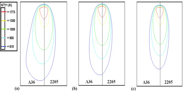
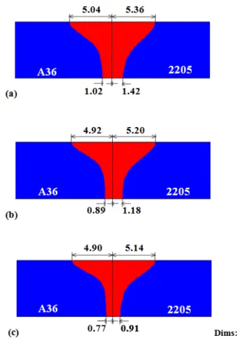
Figure 7 displays the temperature distribution for the samples with different welding heat input at the middle of the joint. It was found that the temperature distribution becomes unsymmetrical due to the difference of expansion and shrinkage rate between duplex stainless steel (2205) and low carbon steel (A36). Since the low carbon steel has higher thermal expansion coefficient than duplex stainless steel. It is also observed that welding heat input plays an important role in the development of weld pool shape and temperature profiles. Figure 8 shows the weld pool profiles for three different heat input. Increasing the heat input causes an enlargement of the weld pool width. For example, the half weld FZ width on the top surface increased by 1.15% for the duplex stainless steel side and 0.4% for the carbon steel side as the welding heat input changes from 1.75 kJ/mm to 1.94 kJ/mm. While, the half weld FZ width on the bottom surface increased by 22.88% for the duplex stainless steel side and 13.48% for the carbon steel side for the same changes in the welding heat input. The asymmetry of the weld pool is clearly noticeable. It is also observed that improper fusion of the materials takes place during the solidification stage as the process is rapid, which corresponding to the heat input of 1.75 kJ/mm. Therefore, using such finite element model, it is possible to investigate the weld fusion zone size and geometry under any requested welding parameters.
Fig. 8. Weld fusion zone of 6.8 mm dissimilar 2205–A36 thick plate for a heat input of (a) 2.25 kJ/mm, (b) 1.96 kJ/mm, and (c) 1.75 kJ/mm
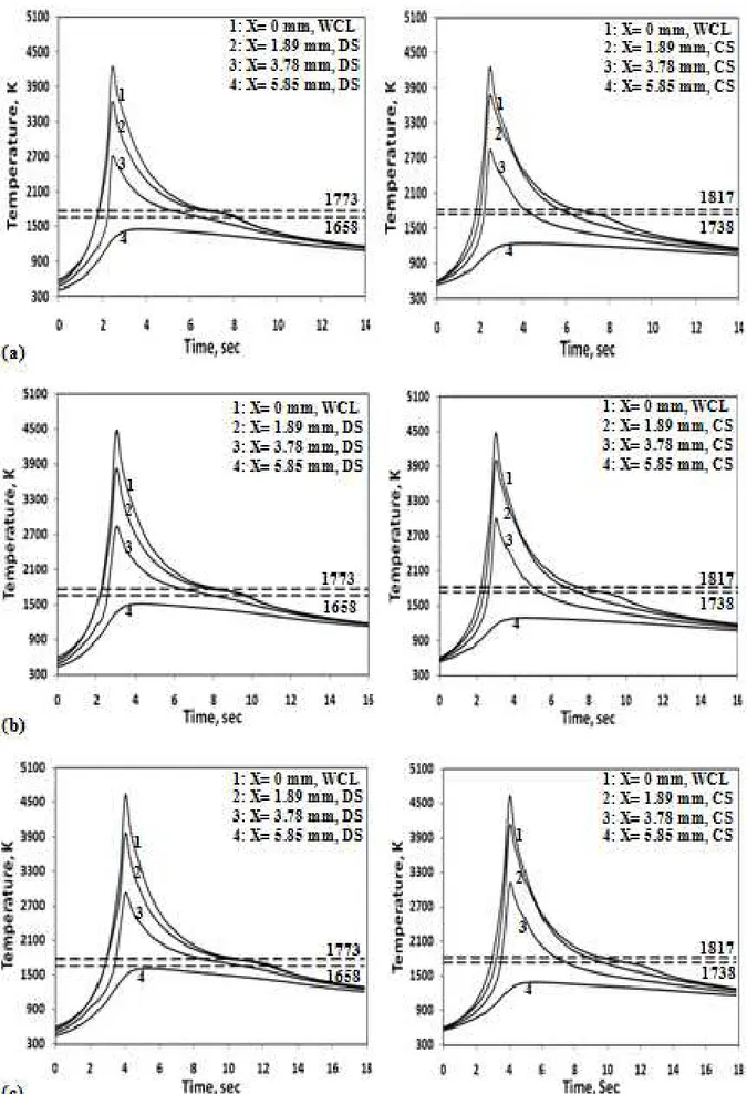
6.2.Weld Thermal Cycles
Conclusions and Outlook
The following conclusions may be drawn from this analysis:
It is possible to analyze the three-dimensional transient thermal analysis for the Keyhole PAW process of dissimilar steels using the finite element method combined with an adaptive heat source model.
A good agreement has been found between the predicted and the measured weld pool size and geometry that verify the validity of the employed model.
The effect of fluid flow and solidification of the weld pool are considered analytically; therefore, good predictions of the transient isotherms and the weld pool geometry are obtained.
Increasing the heat input causes an enlargement of the weld pool width. This effect is more distinct for the duplex stainless steel side than the low carbon steel side.
If the heat input is decreased to 1.75 kJ/mm in the keyhole PAW dissimilar 2205–A36 welds, there is a risk of having improper fusion of the materials.
The results of the built model can be used for the optimization of Keyhole PAW processes to achieve sufficient energy and deep penetration.
The results obtained can be used for future analysis and optimization of residual stress distributions.
Acknowledgments
The authors would like to thank Prof. Dr. Hassan Abouseeda, Professor of Structural Engineering, Alexandria University, Egypt, for his support and useful discussions.
References
[1] Weman, K., Welding processes handbook, 1st ed., Woodhead, England, 2003, pp. 38, 39.
[2] Urena, A., Otero, E., Utrilla, M. V., and Munez, C. J., “Weldability of a 2205 duplex stainless steel using plasma arc welding,” J Mater Process Technol, Vol. 182, No. 1-3, 2007, pp. 624–631.
[3] Zheng, S., Dayou, P., and Ingegerd, A., “Effect of dual torch technique on duplex stainless steel welds,” Mater Sci Eng A, Vol. 356, No. 1-2, 2003, pp. 274–282.
[4] Taban, E., “Joining of duplex stainless steel by plasma arc, TIG and plasma arc+TIG welding processes,” Mater Manuf Process, Vol. 23, No. 8, 2008, pp. 871–878.
[5] Taban, E., “Toughness and microstructural analysis of super duplex stainless steel joined by plasma arc welding,” J Mater Sci, Vol. 43, No. 12, 2008, pp. 4309–4315.
[6] Migiakis, K., Daniolos, N., and Papadimitriou, G. D., “Plasma keyhole welding of UNS S32760 super duplex stainless steel: microstructure and mechanical properties,” Mater Manuf Process, Vol. 25, No. 7, 2010, pp. 598–605.
[7] Barnhouse, E. J., and Lippold, J. C., “Microestructure /Property Relationships in Dissimilar Welds Between Duplex Stainless Steels and Carbon Steels,” Weld J, Vol. 77, No. 12, 1998, pp. s477-487.
[8] Mendoza, B. I., Maldonado, Z. C., Albiter, H. A., and Robles, P. E., “Dissimilar Welding of Superduplex Stainless Steel/HSLA Steel for Offshore Applications Joined by GTAW,” ENG, Vol. 2, No. 7, 2010, pp. 520–528.
[9] Keanini, R. G., and Rubinsky, B., “Three-dimensional simulation of the plasma arc welding process,” Int J Heat Mass Transfer, Vol. 36, No. 13, 1993, pp. 3283–3298.
[10] Fan, H. G., and Kovacevic, R., “Keyhole formation and collapse in plasma arc welding,” J Phys D Appl Phys, Vol. 32, No. 22, 1999, pp. 2902–2909.
[11] Wu, C. S., Wang, H. G., and Zhang, Y. M., “A new heat source model for keyhole plasma arc welding in FEM analysis of the temperature profile,” Weld J, Vol 85, No. 12, 2006, pp. 284–291.
[12] Wu, C. S., Hu, Q. X., and Gao, J. Q., “An adaptive heat source model for finite-element analysis of keyhole plasma arc welding,” Comput Mater Sci, Vol. 46, No. 1, 2009, pp. 167–172.
[13] Wang, H. X., Wei, Y. H., and Yang, C. L., “Numerical simulation of variable polarity vertical-up plasma arc welding process,” Comput Mater Sci, Vol. 38, No. 4, 2007, pp. 571–587.
[14] ABAQUS User’s Manual, Version 6.10, Karlsson & Sorensen, Inc., Hibbitt, 2010.
[15] Labudovic, M., Hu, D., and Kovacevic, R., “Three-dimensional finite element modelling of laser surface modification,” I Mech E, Vol. 214, No. 8, 2000, pp. 683–692.
[16] Punitharani, K., Murugan, N., and Sivagamai, S. M., “Finite element analysis of residual stresses and distortion in hard faced gate valve,” J Sci Ind Res, Vol. 69, No. 2, 2010, pp. 129–134.
[17] Jiang, W., Yahiaoui, K., Hall, F. R., and Laoui, T., “Finite element simulation of multipass welding: full three-dimensional versus generalized plane strain or axisymmetric models,” J Strain Analysis, Vol. 40, No. 6, 2005, pp. 587–597.
[19] Deng, D., and Murakawa, H., “Finite element analysis of temperature field, microstructure and residual stress in multi-pass butt-welded 2.25Cr–1Mo steel pipes,” Comput Mater Sci, Vol. 43, 2008, pp. 681–695.
[20] Abid, M., and Qarni, M. J., “3D thermal finite element analysis of single pass girth welded low carbon steel pipe-flange joints,” Turkish J Eng Env Sci, Vol. 33, 2009, pp. 1–13.
[21] Bonifaz, E. A., and Richards, N. L., “Modeling cast IN-738 superalloy gas tungsten arc welds,” Acta Materialia, Vol. 57, 2009, pp. 1785–1794.