Tiago Jorge Cardoso Bento
Licenciado em Ciências da Engenharia Electrotécnica e de Computadores
Multipacket reception in the presence of
in-band full-duplex communication
Dissertação para obtenção do Grau de Mestre em Engenharia Electrotécnica e de Computadores
Orientador :
Luís Filipe Lourenço Bernardo, Prof. Dr.,
FCT-UNL
Júri:
Presidente: Rodolfo Alexandre Duarte Oliveira, Prof. Dr.
FCT-UNL
Arguente: Paulo Rogério Barreiros D’Almeida Pereira, Prof. Dr.
IST-UL
Vogal: Luís Filipe Lourenço Bernardo, Prof. Dr.
iii
Multipacket reception in the presence of in-band full-duplex communication
Copyright cTiago Jorge Cardoso Bento, Faculdade de Ciências e Tecnologia, Universi-dade Nova de Lisboa
Acknowledgements
First and foremost of all I’d like to thank my adviser Prof. Dr. Luís Bernardo for the de-cisive role he had in all stages of my dissertation. I feel no words can fully describe how grateful I am for all the help he has given me, but it doesn’t stop me from trying. I thank him for the patience, motivation and all the time invested in me. Tackling such a complex project did not come easy, but I feel his guidance made this journey as straightforward as it could.
I’d like to thank all the members of the telecommunication group for their wonderful lectures, which made me want to pursue a career in this area.
I’d like to thank Dr. Francisco Ganhão, not only for the fundamental part his work had in my dissertation, but also for the time he spent teaching me when I was his student three years ago. His lectures were a big part of the reason why telecommunications first started to appeal to me.
I’d like to show my gratitude towards my adviser, Prof. Dr. Rodolfo Oliveira and Insti-tuto das Telecomunicaçõesfor funding me with a research scholarship, allowing me to keep investigating such an interesting topic.
I’m also thankful to the financial support given by the FCT/MEC projects MANY2COMWIN EXPL/EEI-TEL/0969/2013; COPWIN TEL/1417/2012 and ADIN PTDC/EEI-TEL/2990/2012. Without them this research work would not have been possible.
I’m thankful toUniversidade Nova de Lisboa,Faculdade de Ciências e Tecnologiaand Departa-mento de Engenharia Electrotécnica e de Computadoresfor the opportunity and the conditions which allowed me to complete my education.
My colleagues have been a fundamental part of this journey. Without them to distract me and cheer me up when times got tough, the time I spent in college wouldn’t have been nearly as enjoyable. A huge thank you to my high school friends for always being there for me and my apologies for not being able to spend as much time with them as I would have wanted in the last few years. Myonlinefriends while not as close as my
offlinefriends, were just as supportive throughout this period of my life.
viii
the amount of support they have given me throughout all these years. Their efforts were not unnoticed and will never be forgotten.
My dog Baloo also deserves an honourable mention since he was the one that kept me company while I was writing my dissertation.
Last but not least, a huge heartfelt thank you to my girlfriend Vera Martins for the love and friendship she has given me for the past six years. If it wasn’t for her I probably wouldn’t have been able to keep the emotional stability to endure this hard stage of my life.
"I will either find a way or make one"
Abstract
In-Band Full-DupleX (IB-FDX) is defined as the ability for nodes to transmit and receive signals simultaneously on the same channel. Conventional digital wireless networks do not implement it, since a node’s own transmission signal causes interference to the signal it is trying to receive. However, recent studies attempt to overcome this obsta-cle, since it can potentially double the spectral efficiency of current wireless networks. Different mechanisms exist today that are able to reduce a significant part of the Self-Interference (SI), although specially tuned Medium Access Control (MAC) protocols are required to optimize its use. One of IB-FDX’s biggest problems is that the nodes’ in-terference range is extended, meaning the unusable space for other transmissions and receptions is broader. This dissertation proposes using MultiPacket Reception (MPR) to address this issue and adapts an already existing Single-Carrier with Frequency-Domain Equalization (SC-FDE) receiver to IB-FDX. The performance analysis suggests that MPR and IB-FDX have a strong synergy and are able to achieve higher data rates, when used together. Using analytical models, the optimal transmission patterns and transmission power were identified, which maximize the channel capacity with the minimal energy consumption. This was used to define a new MAC protocol, named Full-duplex Mul-tipacket reception Medium Access Control (FM-MAC). FM-MAC was designed for a single-hop cellular infrastructure, where the Access Point (AP) and the terminals im-plement both IB-FDX and MPR. It divides the coverage range of the AP into a closer Full-DupleX (FDX) zone and a farther Half-DupleX (HDX) zone and adds a tunable fair-ness mechanism to avoid terminal starvation. Simulation results show that this protocol provides efficient support for both HDX and FDX terminals, maximizing its capacity when more FDX terminals are used.
Resumo
Comunicação full-duplex na mesma banda(IB-FDX) traduz-se na capacidade dos nós trans-mitirem e receberem sinais simultaneamente no mesmo canal. Redes sem fios digitais convencionais não implementam esta tecnologia pois o sinal que é transmitido por um nó causa interferência no sinal que este quer receber. No entanto, estudos recentes procu-ram superar este obstáculo, já que tem o potencial de duplicar a eficiência espectral das redes sem fios atuais. Existem várias abordagens para reduzir oruído interferente próprio
(SI), mas requerem protocolos decontrolo do acesso ao meio(MAC) especiais para optimi-zar a sua utilização. Um dos maiores problemas do IB-FDX é que o alcance da interferên-cia dos nós é estendido, o que resulta numa área inutilizável para outras transmissões e recepções mais abrangente. Esta dissertação propõe utilizarrecepção multi pacote(MPR) para superar este obstáculo e adapta um receptor comequalização no domínio da frequên-cia de portadora única (SC-FDE) a IB-FDX. Os resultados sugerem que MPR e IB-FDX possuem uma sinergia forte que os permite alcançar ritmos superiores quando usados em conjunto. Através de modelos analíticos, foram identificados padrões e potências de transmissão ideais, que permitem maximizar a capacidade do canal com o consumo de energia mínimo. Estas referências foram utilizadas para definir um novo protocolo MAC chamadocontrolo do acesso ao meio com recepção multi pacote e full-duplex(FM-MAC). O protocolo foi desenhado para uma rede celular infraestruturada onde oponto de acesso
(AP) e os terminais utilizam IB-FDX e MPR. O protocolo divide o alcance de cobertura do AP numa zonafull-duplex(FDX) e numa zonahalf-duplex(HDX) e apresenta um meca-nismo de justiça configurável que impede que os terminais fiquem sem acesso ao canal. Os resultados mostram que este protocolo suporta terminais HDX e FDX eficientemente, maximizando a sua capacidade quando são utilizados mais terminais FDX.
Contents
Acknowledgements vii
Abstract xi
Resumo xiii
Acronyms xxv
1 Introduction 1
1.1 Research goals and contributions . . . 2
1.2 Dissertation’s outline . . . 3
2 Related Work 5 2.1 Introduction . . . 5
2.2 Self-interference reducing methods . . . 6
2.2.1 Passive suppression . . . 7
2.2.2 Active cancellation . . . 9
2.3 Self-interference reduction overview . . . 11
2.4 Existing cancellation architectures . . . 12
2.4.1 Rice’s designs . . . 12
2.4.2 Stanford’s designs . . . 13
2.4.3 Princeton’s design . . . 16
2.4.4 Comparison table . . . 17
2.5 Full-duplex medium access control protocols . . . 18
2.5.1 Medium access control protocols optimized for single-hop networks (Infrastructure) . . . 19
2.5.2 Medium access control protocols optimized for multi-hop networks (Ad-hoc) . . . 23
2.6 Full-duplex and the inter-terminal interference . . . 25
xvi CONTENTS
2.7.1 Receiver perspective . . . 26
2.7.2 Transmitter perspective . . . 27
2.7.3 Transreceiver perspective . . . 28
2.7.4 Hybrid solutions . . . 29
3 MPR in the presence of IB-FDX communication 31 3.1 Introduction . . . 31
3.2 System characterization . . . 32
3.2.1 Multipacket detection receiver performance . . . 32
3.2.2 Analytical performance model . . . 35
3.3 Performance analysis . . . 35
3.3.1 Characterization of a single packet reception system . . . 36
3.3.2 Characterization of a multipacket reception system . . . 41
3.4 MAC protocol requirements . . . 46
4 FM-MAC protocol 49 4.1 Introduction . . . 49
4.2 Protocol design . . . 49
4.2.1 Objectives . . . 49
4.2.2 Protocol characterization . . . 50
4.2.3 Packet structure . . . 51
4.2.4 Operating modes . . . 52
4.2.5 Maximum number of transmission reached and failed reception of physical layer headers . . . 55
4.2.6 Power control . . . 57
4.2.7 Inter-terminal interference and the exclusion synchronization con-trol packet . . . 59
4.2.8 Maximizing full-duplex communications and fairness control . . . 59
4.3 Simulation results . . . 62
4.3.1 Simulation scenario . . . 62
4.3.2 Average number of transmissions . . . 64
4.3.3 Queuing delay . . . 65
4.3.4 Energy efficiency . . . 66
4.3.5 Multipacket reception at the terminal . . . 67
4.3.6 Throughput . . . 68
4.3.7 Simulation results overview . . . 71
5 Conclusions 73 5.1 Final considerations . . . 73
CONTENTS xvii
A Minimum transmission power tables 81
A.1 For half-duplex . . . 82
A.2 For a self-interference reduction of 80dB . . . 83
A.3 For a self-interference reduction of 90dB . . . 84
A.4 For a self-interference reduction of 100dB . . . 85
A.5 For a self-interference reduction of 110dB . . . 86
B Simulator’s structure 87 B.1 Global architecture . . . 87
B.2 Distance and channel coefficient matrices . . . 90
List of Figures
2.1 Anatomy of a separate-antenna IB-FDX node with multiple transmit
an-tennas and multiple receive anan-tennas. Adapted from [SSGBRW14]. . . 6
2.2 SI reducing methods. Adapted from [SPDS13]. . . 7
2.3 Antenna separation . . . 7
2.4 Beam separated antennas . . . 8
2.5 Theoretical scheme of a RF absorber . . . 8
2.6 (a) pre-mixer architecture; (b) post-mixer architecture . Adapted from [ESS13]. 10 2.7 At-BB architecture. Adapted from [ESS13]. . . 10
2.8 Reflected Path . . . 12
2.9 Model of the transceiver. Adapted from [DS10]. . . 12
2.10 Block diagram of the transceiver. Adapted from [CJSLK10]. . . 14
2.11 Block diagram of the transceiver. Adapted from [JCKBSSLKS11]. . . 15
2.12 Block diagram of the transceiver. Adapted from [BMK13]. . . 16
2.13 (a) MIDU’s two level cancellation; (b) design scaled to MIMO. Adapted from [AKSRC12]. . . 17
2.14 IB-FDX at the network level. (a) relay topology; (b) bidirectional topology. Adapted from [SSGBRW14]. . . 19
2.15 FD-MAC’s packet structure. Adapted from [SPS11]. . . 20
2.16 FD-MAC’s timeline of events. (a) bidirectional communication; (b) relay communication. Adapted from [SPS11]. . . 21
2.17 Operation with proposed protocol. Adapted from [MB12]. . . 23
2.18 Operation with proposed protocol. Adapted from [XZ14]. . . 24
2.19 (a) spacial reuse for HDX; (b) spacial reuse for FDX. Adapted from [XZ14] 25 2.20 Classification of techniques applied for MPR. Adapted from [LSW12]. . . 26
2.21 H-NDMA’s reception scheme. Adapted from [GPBDOP13]. . . 30
3.1 System model . . . 32
xx LIST OF FIGURES
3.3 BER performance overPt. . . 37
3.4 SPR BER performance over PAP t = PtMT(a) for various distances and SIR values. . . 38
3.5 Comparison between HDX and FDX’s BER performance over EB N0. . . 39
3.6 (a) plain model; (b) extended model. . . 40
3.7 Minimum transmission power for a PER below 1% over distance, for a line of sight indoor hotspot model [Itu]. . . 40
3.8 Performance case for MPR . . . 41
3.9 SPR, MPR-IC and MPR-T BER performance over PAP t = PtMT(a) for HDX, FDX, various distances and SIR values. . . 43
3.10 SPR, MPR-IC and MPR-T throughput for HDX and FDX with several SIR values. . . 44
3.11 Aggregated throughput over distance. (a) SPR; (b) MPR-IC;(c) SPR-T; (d) MPR-T. . . 46
4.1 FM-MAC’s packet exchange. . . 50
4.2 SYNC’s packet structure . . . 51
4.3 ACK’s packet structure . . . 52
4.4 UO mode . . . 53
4.5 DO mode . . . 54
4.6 UND mode . . . 55
4.7 AP forced to dropped packet. . . 56
4.8 MT forced to dropped packet. . . 56
4.9 (a) exclusive SYNC; (b) exclusive packet exchange between the AP and MT(b). . . 59
4.10 MTs’ distribution. (a) 3 MT scenario; (b) 10 MT scenario. . . 63
4.11 Average number of transmissions. . . 64
4.12 Average queuing delay . . . 65
4.13 Average EPUP for the10FDX - 0HDXand0FDX - 10HDXscenarios. . . . 66
4.14 Average EPUP for the5FDX - 5HDXscenario. . . 67
4.15 MPR resolution percentage for the10FDX - 0HDX . . . 67
4.16 Downlink and aggregate uplink’s throughput . . . 68
4.17 Aggregate throughput (uplink + downlink) . . . 69
4.18 Aggregate throughput for 90% downlink load and 270% aggregate uplink load with 3 MTs. . . 69
4.19 Aggregate throughput for 90% downlink load and 900% aggregate uplink load with 10 MTs. . . 70
4.20 Packets received by each Mobile Terminal (MT) for 90% downlink load and 900% aggregate uplink load with 10 MTs. . . 70
LIST OF FIGURES xxi
B.1 Flowchart representing the simulator’s process. . . 88 B.2 Determined parameters for 2 MTs. . . 91 B.3 statsTablefor 2 FDX MTs and 1 HDX MT for 90% downlink load and 270%
aggregate uplink load. . . 92 B.4 logTablefor 2 FDX MTs and 1 HDX MT for 90% downlink load and 270%
List of Tables
2.1 SIR achieved. Adapted from [DS10]. . . 13 2.2 Comparison table . . . 17
3.1 OptimalPtfor each SIR value. . . 38
3.2 Zones’ radius for each value of SIR. . . 41 3.3 (a) Average number of transmissions required; (b) Maximum number of
transmissions required. . . 42
4.1 Packets’ duration. . . 62 4.2 MT’s distribution per scenario. . . 63
Acronyms
ACK ACKnowledgement control packet
ADC Analog-to-Digital Converter
AP Access Point
APTX Access Point Transmission
At-BB At-BaseBand
At-RF At-Radio-Frequency
B-NDMA Blind Network-assisted Diversity Multiple Access
BER Bit-Error Rate
BS Base Station
CA Collision Avoidance
CD Collision Detection
CDMA Code Division Multiple Access
CRC Cyclic Redundancy Check
CSI Channel State Information
CSMA Carrier Sense Multiple Access
CTS Clear-To-Send
DAC Digital-to-Analog Converter
DO Downlink Only
xxvi ACRONYMS
EPUP Energy Per Useful Packet
FD-MAC Full-Duplex Medium Access Control
FDMA Frequency Division Multiple Access
FD Full-Duplex
FDX Full-DupleX
FF-NDMA Feedback-Free Network-assisted Diversity Multiple Access
FFT Fast Fourier Transform
FIFO First In First Out
FM-MAC Full-duplex Multipacket reception Medium Access Control
H-ARQ Hybrid Automatic Repeat reQuest
H-NDMA Hybrid automatic repeat request Network Division Multiple Access
HD Half-Duplex
HDX Half-DupleX
HPA High-Power Amplifier
HOL Head-Of-Line
IB-DFE Iterative Block Decision-Feedback Equalizer
IB-FDX In-Band Full-DupleX
ICA-CooPNDMA Independent Component Analysis CooPerative Network-assisted Di-versity Multiple Access
ICA-NDMA Independent Component Analysis Network-assisted Diversity Multiple Ac-cess
ID IDentification
IEEE Institute of Electrical and Electronics Engineers
IFFT Inverse Fast Fourier Transform
ITI Inter-Terminal Interference
ITU International Telecommunication Union
JFI Jain’s Fairness Index
xxvii
LNA Low-Noise Amplifier
LR-WPN Low-Rate Wireless Personal area Network
LTE Long-Term Evolution
MAC Medium Access Control
MAI Multiple Access Interference
MIDU MImo full-DUplex
MIMO Multiple-Input and Multiple-Output
MPR MultiPacket Reception
MPR-IC MultiPacket Reception by successive Interference Cancellation
MPR-T MultiPacket Reception by Time diversity
MSE Mean Square Error
MT Mobile Terminal
MUD MultiUser Detection
NA Not Applicable
NDMA Network-assisted Diversity Multiple Access
OFDMA Orthogonal Frequency Division Multiple Access
OQPSK Offset Quadrature Phase-Shift Keying
PER Packet Error Rate
PHY PHYsical layer
PIC Parallel Interference Cancellation
PR Packets Received
QPSK Quadrature Phase Shift Keying
RF Radio-Frequency
RTS Request To Send
RTXN ReTransmission Needed
S-FDX Semi Full-DupleX
xxviii ACRONYMS
SI Self-Interference
SIC Self-Interference Cancellation
SICTA Successive Interference Cancellation Tree Algorithm
SINR Signal-to-Interference-plus-Noise Ratio
SIR Self-Interference Reduction
SPR Single Packet Reception
SPR-T Single Packet Reception by Time diversity
SRB Shared Random Backoff
SYNC SYNCronization control packet
TUOS Terminal Unique Orthogonal spreading-Sequence
UND Uplink aNd Downlink
UO Uplink Only
WAN Wireless Access Networks
1
Introduction
Ever since modern wireless digital communication was first used in the Hawaiian Is-lands in the early 1970s that it has been an evolving subject. At the time the researchers were looking for a way to connect the computers at the University of Hawaii to the main computer in Honolulu. This way the ALOHANET system was born and offered a simple way to transmit packet data wirelessly [Tan10]. Thanks to the constant development and research in the area of wireless networks, this segment of the communications industry has grown from simple system, to one of the most important and fast moving industries around [Gol05; Mol10].
1. INTRODUCTION 1.1. Research goals and contributions
systems like cellular and IEEE 802.11 avoid IB-FDX, since the idea of transmitting and re-ceiving signals on the same channel has always been considered ineffective due to the in-terference generated [SSGBRW14; Gol05]. Most studies agree that if the inin-terference gen-erated by the node can be suppressed successfully, transmitting and receiving using the same dedicated bandwidth can double the spectral efficiency of a system which in turn can double the throughput in comparison to an ordinary HDX system [BMK13; NTPL14; DMBS12a; CJSLK10]. [CJSLK10] considers that despite this being IB-FDX’s main advan-tage, the systems can still benefit from much more than higher data rates at the physical layer.
[CJSLK10] presents a design where it is suggested that the Access Point (AP) should al-ways be forwarding packets to a destination while it is receiving packets from a source. This allows the other nodes in the network to recognize that a transmission is already in progress forcing them to delay their transmissions and thereby avoiding collisions (solv-ing the hidden node problem). In [CTK14] it is shown how the interference generated from all nodes using the dedicated bandwidth simultaneously can be optimized to act as artificial noise against passive attackers (radio eavesdroppers). This allows an im-provement of the secrecy of the messages transmitted at the physical level. [CJSLK10] also shows a FDX radio that (unlike traditional HDX radios) is capable of sensing while transmitting in order to avoid collisions. This is particularly useful when considering cognitive radio applications, as secondary users can only use the dedicated bandwidth if the primary user is not using it at that moment. IB-FDX communication was also used to enable relay switching, creating a one-way flow of data traffic [MB12].
Despite the real-world applications and benefits of IB-FDX, two main obstacles lie in the way of enabling this technology. One is the interference that a transmitting IB-FDX terminal causes to itself, which interferes with the desired signal being received by that terminal. The second is Inter-Terminal Interference (ITI), which occurs in IB-FDX net-works between terminals that may themselves be non-IB-FDX [SSGBRW14].
The work developed in this dissertation intends to address the ITI by applying Multi-Packet Reception (MPR) techniques. MPR is a technology that allows a node to receive more than one packet from multiple concurrent transmissions, making it possible to de-code the packets, even if a collision occurred [LSW12].
1.1
Research goals and contributions
This research work has two main goals:
• The implementation of a system that uses MPR to handle the ITI generated by IB-FDX communications;
• The design of a Medium Access Control (MAC) protocol that optimizes channel access.
1. INTRODUCTION 1.2. Dissertation’s outline
• A physical layer analysis of the performance of the MPR IB-FDX system. The model presented in chapter 3 was accepted for publication in the2015 ICC’s Workshop 5G & Beyond - Enabling Technologies and Applications[BBDOPA15];
• A MAC protocol named Full-duplex Multipacket reception Medium Access Con-trol (FM-MAC) was designed and a system level simulator was implemented using MATLAB, which considers the physical layer performance models. We plan to pre-pare a conference paper covering the FM-MAC protocol, and an extended version, with a stochastic system level’s performance model, for a journal.
1.2
Dissertation’s outline
This rest of this dissertation is organized as follows:
Chapter 2 starts by classifying the different types of mechanisms proposed to enable IB-FDX communication as well as some of the most noteworthy designs. A small de-scription of the current state of the art of MPR technology is given, as a possible solution to address the interference sensitivity of IB-FDX networks, therefore proving the rele-vance of the system developed in this dissertation.
Chapter 3 starts by analytically describing the MPR receiver from [GDBO12] and by the modifications that were performed in order to have it support IB-FDX communication. This is followed by an analysis of how the interference generated by the transmission of a FDX transceiver influences the performance of MPR systems. It then presents a set of simulations that characterize a system in which nodes support IB-FDX and MPR.
Chapter 4 describes the FM-MAC protocol that is able to control a single-hop cellular infrastructure system, where the AP supports both IB-FDX and MPR. The performance is evaluated using a set of simulations that measures the effects the relation between the number of HDX and FDX MTs have in the system’s delay, throughput and Energy Per Useful Packet (EPUP).
2
Related Work
2.1
Introduction
Over the years there has been some major breakthroughs in the area of digital wireless communications, with the focus on achieving a higher data transfer rate and bandwidth efficiency. Future developments will continue this trend, requiring protocols that are ef-ficient at the physical layer and optimized at the uppers layers, to attain a higher spectral efficiency than the ones we already possess with the techniques that are available at the current time [Bha06].
Telecommunications standards have proposed two approaches for two-way communi-cation: HDX and FDX transmission. HDX transmission is a two-way non-simultaneous communication, whereas FDX transmission is a two-way simultaneous communication. In other words, in a HDX scenario the nodes take turns transmitting while in a FDX sce-nario nodes can transmit and receive at the same time.
Current systems usually use separate uplink and downlink channels as a way to achieve FDX communication. These channels are separated using orthogonal signalling dimen-sions, such as time or frequency (e.g. IEEE 802.11 or Long-Term Evolution (LTE)) [Gol05]. This leads to a loss of spectral efficiency as the same channel can only be used for one transmission [BMK13]. Recent research focused on developing IB-FDX radios. This is a major paradigm shift in wireless communications, as the idea of transmitting and receiv-ing signals on the same channel has always been considered ineffective due to the Self-Interference (SI) generated [Gol05]. This concept has the potential to double the spectral efficiency.
2. RELATEDWORK 2.2. Self-interference reducing methods
JCKBSSLKS11] proposed different techniques to cancel this SI.
The prototypes developed often involve additional hardware to implement the IB-FDX transmission, usually using different antennas for transmission and reception, although more ambitious designs use a single antenna for both [Kno12; BMK13]. It was also shown that although IB-FDX increases the bandwidth efficiency, it also increases the interference sensitivity [XZ14], reducing its effectiveness in a multi-hop network.
This chapter starts by classifying the different types of mechanisms proposed to reduce the levels of SI, providing a small description for each one and giving examples of de-signs that use those mechanisms. Secondly, some of the most noteworthy FDX architec-tures are described, compared and contrasted. Afterwards, some of the most meaningful MAC protocols developed for IB-FDX are explained. Lastly, a small description of the current state of the art of MPR technology is given, as a possible solution to address the interference sensitivity of IB-FDX networks to transmissions of external nodes.
2.2
Self-interference reducing methods
As mentioned before, the biggest problem that the scientific community is having with the development of IB-FDX radios is the amount of SI generated at a FDX node. This results from the fact that the transmit and receive antenna are either the same or relatively close to each other. These conditions make the SI at the receiver antenna much stronger than the signal that it actually wants to receive.
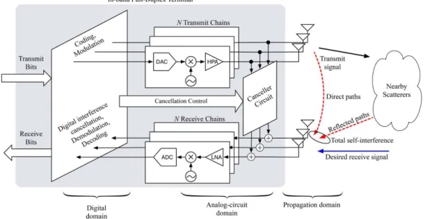
Figure 2.1: Anatomy of a separate-antenna IB-FDX node with multiple transmit antennas and multiple receive antennas. Adapted from [SSGBRW14].
2. RELATEDWORK 2.2. Self-interference reducing methods
signal to cancel the SI, by injecting a cancellation waveform into the receive signal path to null the SI [ESS13]. This cancellation waveform is an inverted copy of the original sig-nal. Figure 2.1 depicts a conventional separate-antenna IB-FDX node. The transmission chain of the transceiver accepts a bitstream that is coded and modulated in the digi-tal domain. This bitstream is then converted to analog with a Digidigi-tal-to-Analog Con-verter (DAC), upconverted to a high carrier frequency and amplified using a High-Power Amplifier (HPA). The reception chain is constituted by a Low-Noise Amplifier (LNA), downconverter and an Analog-to-Digital Converter (ADC) and allows the transceiver to function as a receiver in the same frequency band. The existing SI reducing methods that enable IB-FDX can be divided in the categories shown in figure 2.2, which will be described individually in this section, along with some examples.
Self-Interference Reducing Methods
Passive Suppression Active Cancellation
Active Analog Active Digital
At-Radio-Frequency Canceller
At-Baseband Canceller
Pro-Mixer Pre-Mixer
Figure 2.2: SI reducing methods. Adapted from [SPDS13].
2.2.1 Passive suppression
2.2.1.1 Antenna separation
Antenna separation is the simplest method of reducing SI. It consists in taking advan-tage of the attenuation generated from the physical distancedbetween the transmit and receiving antenna.
d
Full-Duplex Node
Tx Rx
Figure 2.3: Antenna separation
2. RELATEDWORK 2.2. Self-interference reducing methods
by itself: [DS10] reports that by simply separating the antennas by 20 cm led to a can-cellation of 39 dB and separating them by 40 cm led to a cancan-cellation of 45dB. While this suppression method is not good enough to make a robust system by itself, there is no reason not to exploit this convenient phenomenon in a two antenna scheme, as long as the terminal’s design allows it. Therefore, antenna placement is an important topic to consider when designing a FDX system, as this allows to further increase the amount of Self-Interference Reduction (SIR).
2.2.1.2 Directional isolation
In directional isolation, directional antennas’ coverage area is exploited in order to sepa-rate the beams of the transmitter and receiver. Directional antennas have a fixed beamwidth, measured in degrees, that illustrates the coverage area or radiation pattern of a particular antenna. This way, designs can be projected in a way that the gain of the transmit antenna is low in the direction of the receive antenna in order to reduce SI as in Rice’s [ESS13].
Tx Rx
Figure 2.4: Beam separated antennas
2.2.1.3 Absorptive shielding
In absorptive shielding, SI is suppressed by placing a slab of Radio-Frequency (RF) ab-sorber material between the transmitter and the receiver so that it inhibits the propaga-tion of electromagnetic radiapropaga-tion. An example of this approach is Rice’s [ESS13].
Full-Duplex Node
Tx Rx
2. RELATEDWORK 2.2. Self-interference reducing methods
2.2.1.4 Cross-polarization
Cross-polarization consists in modulating the polarization of two waves in order for them to be orthogonal between them. Cross-polarisation can be linear (two waves polarised as horizontal and vertical) or circular (two waves polarised as right-hand circular and left-hand circular).
In theory, if the waves are polarised orthogonally, the interference between them is non-existent and it allows establishing two simultaneous links at the same frequency band. This is called frequency re-use and it has been used to increase the capacity on satellite networks systems, without increasing the bandwidth allocated. Unfortunately, imperfec-tion of the antennas and depolarisaimperfec-tion of the waves by the transmission medium leads to interference between the two links [MB02]. In [ESS13], a IB-FDX design is suggested that transmits with horizontal polarization and receives with vertical polarization.
2.2.2 Active cancellation
In active cancellation, a cancelling signal is generated by inverting the phase of the known interference signal and injected into the received signal in order to cancel its interference. Theoretically, a signal and its opposite cancel each other out perfectly, but the exact in-verse of a signal is sometimes difficult to estimate because of phase noise, multi-path reflections and other random components of the received SI signal unknown to the can-celler [SPDS13]. Active cancellation methods are also restricted by the limited dynamic range. The dynamic range refers to the range of the input signal levels that can be re-liably measured simultaneously [HVK01]. Since the transmit and receive antenna are either the same or relatively close to each other, the signal passed to the analog-circuits can be above the dynamic range, which causes the measuring device to saturate, result-ing in inaccurate estimations. The limited dynamic range affects non-ideal amplifiers, oscillators, ADCs, DACs and makes total cancellation impossible, even if the SI signal is perfectly known [DMBS12b].
2.2.2.1 Analog cancellation
Analog cancellation can be divided in two main categories, depending on where the can-cellation occurs.
At-radio-frequency canceller
In an At-Radio-Frequency (At-RF) canceller the signal and its inverse are added at the carrier’s frequency. At-RF cancellers can be subdivided based on where the cancellation signal is generated. A pre-mixer generates the cancelling signal prior to RF upconver-sion. An example of an pre-mixer is Rice’s [DS10]. A post-mixer generates the cancelling signal after RF upconversion. An example of post-mixer is Stanford’s [JCKBSSLKS11]. A block diagram of At-RF cancellers is shown in figure 2.6, wherexI denotes the SI
sig-nal,hI denotes the SI signal after upconversion, f(.) denotes the pre-mixer’s processing
2. RELATEDWORK 2.2. Self-interference reducing methods
RF
up hI
RF up
xI residual
f(.)
(a)
RF
up hI
RF up
xI
g(.)
residual
(b)
Figure 2.6: (a) pre-mixer architecture; (b) post-mixer architecture . Adapted from [ESS13].
A particular case of the post-mixer mechanism is the antenna canceller. In antenna cancel-lation, transmit antennas are positioned in a way so they destructively add at the receive antenna. The processing occurs At-RF and the signals transmitted by the antennas are the negative of each other [SPDS13]. Examples of designs that use antenna cancellation are Stanford’s [CJSLK10] and Princeton’s [AKSRC12].
At-Baseband Canceller
In an At-BaseBand (At-BB) canceller, the signal and its inverse are added at analog base-band frequency. This type of architecture is uncommon as the majority of the analog cancellation techniques occur in the At-RF stage. An example of an At-BB canceller is Rice’s [KLA13]. A block diagram of At-BB cancellers is shown in figure 2.7, where xI
denotes the SI signal, hI denotes the SI signal after upconversion and s(.) denotes the
At-BB’s processing function.
RF
up hI
xI residual
s(.)
RF down
Figure 2.7: At-BB architecture. Adapted from [ESS13].
2.2.2.2 Digital cancellation
2. RELATEDWORK 2.3. Self-interference reduction overview
techniques unable to provide the suppression needed for a working IB-FDX system by themselves. Therefore, active digital cancellation is the final step of current designs, in order to avoid the saturation of the ADCs.
Digital cancellation is an essential component in the current FDX designs. Nearly every reported design uses this approach as it dispenses the addition of new components to the FDX transceiver. Some examples are Stanford’s [BMK13; DS10] and Rice’s [JCKBSS-LKS11].
2.3
Self-interference reduction overview
A logical approach to the challenge of creating FDX designs would be to combine ev-ery suppression and cancellation technique in order to achieve the highest SIR possible, assuming that each stage is independent of the stages prior to it. However, [Dua12] ex-perimentally observed that this is not the case, leading to the conclusion that the total cancellation of a FDX system is not the sum of the maximum SI cancelled by each stage in isolation. It also suggests that when a stage cancels more SI, the next stages will cancel less.
According to [SPDS13], the phase noise associated with the local oscillators at the trans-mitter and receiver is responsible for three major issues:
1. It limits the amount of analog cancellation in a FDX system;
2. It makes the analog and digital cancellers depend on each other in a cascaded sys-tem;
3. It makes the passive suppression methods impact the amount of analog cancellation in pre-mixer designs.
In [SPDS13] it is analytically clarified the experimental results observed in [DS10; JCKB-SSLKS11; CJSLK10; Dua12; KSRZB11] and suggested that phase noise is one of the major bottlenecks in the current FDX designs. Therefore, improving phase noise characteristics in local oscillators can significantly improve the amount of active cancellation.
Passive suppression methods are mostly limited by not being able to address the reflected path (depicted in figure 2.8) [ESS13].
Active cancellation methods are mostly limited by RF impairments such as phase noise and limited dynamic range [ESS13; SPDS13; DMBS12b].
Active digital cancellation will only help cancel SI if the SI channel is not known perfectly [SPDS12]. In [DDS11] it is suggested that active digital cancellation should be used as a "safety net", for the frames where active analog cancellation achieves less than 32dB of cancellation. If it is not applied selectively, it can actually increase the amount of SI in the system.
2. RELATEDWORK 2.4. Existing cancellation architectures
Direct P ath
Full-Duplex Node
Reflected Path
Tx Rx
Figure 2.8: Reflected Path
studies seem to agree that passive suppression and active cancellation applied together will always result in superior SIR than just one of them.
2.4
Existing cancellation architectures
This section’s goal is to compare and contrast the different designs and the SIR that each one of them can achieve.
2.4.1 Rice’s designs
2.4.1.1 Rice’s [DS10]
Uses off-the-shelf Multiple-Input and Multiple-Output (MIMO) radios to implement FDX communication. A model of the transceiver is shown in figure 2.9.
Figure 2.9: Model of the transceiver. Adapted from [DS10].
It is a simple pre-mixer design wherexi,ciandyi denote MTi’s signal transmitted,
can-celler signal and desired signal respectively. Therefore, ifci = −(hhazb)xi the analog
2. RELATEDWORK 2.4. Existing cancellation architectures
Antenna separation Antenna separation Digital cancellation
Antenna separation Analog cancellation
Antenna separation Analog cancellation Digital cancellation
20cm 39dB 70dB 72dB 78dB
40cm 45dB 76dB 76dB 80dB
Table 2.1: SIR achieved. Adapted from [DS10].
2.4.1.2 Rice’s [ESS13]
Rice’s [ESS13] exploited passive suppression to its fullest, by using antenna separation, absorptive shielding, directional isolation and cross-polarization. Moreover, analog and digital cancellation mechanisms were still employed after the passive suppression ones. This article measures an average of 70dB of SI suppression associated to the passive mechanisms and an average of 20dB to the active ones. It reports a maximum of 100dB SIR achieved with all techniques combined.
2.4.2 Stanford’s designs
2.4.2.1 Stanford’s [CJSLK10]
Stanford’s [CJSLK10] design uses a combination of antenna cancellation, analog cancel-lation and digital cancelcancel-lation to create a post-mixer transceiver that can apply FDX com-munications to IEEE 802.15.4 networks1.
A block diagram of the transceiver is shown in figure 2.10.
The first stage of this design is the antenna cancellation. As shown in figure 2.10, if the wavelength of transmission is λ, and the distance of the receive antenna is dfrom one transmit antenna, then the other transmit antenna is placed atd+ λ2 away from the re-ceive antenna, causing the signal from the two transmit antennas to add destructively. It is also essential that the signals’ amplitude at the receiver match. Therefore, power splitters introduce 6dB attenuation in order for the power transmitted by Tx1 to be 6dB lower than the one by Tx2.
After the antenna cancellation stage, the transceiver applies its analog cancellation through the Qhx220 chip, a narrowband noise canceller. The QHx220 chip takes the known SI and received signals as inputs and outputs the received signal with the SI subtracted out. Lastly, digital cancellation is applied by software, as soon as the signal is discretized by the ADC.
This article measures 20dB to 30dB of Self-Interference Cancellation (SIC) to antenna can-cellation, 20dB of SIC to analog cancellation and 10dB of SIC to digital cancellation. It reports a maximum of 60dB SIR achieved with all techniques combined.
2. RELATEDWORK 2.4. Existing cancellation architectures
Figure 2.10: Block diagram of the transceiver. Adapted from [CJSLK10].
2.4.2.2 Stanford’s [JCKBSSLKS11]
Stanford’s [JCKBSSLKS11] design is a post-mixer transceiver that uses signal inversion and adaptive cancellation in order to achieve the required SIR for FDX communication. The idea behind this design is that any radio that inverts a signal through adjusting phase will always encounter a bandwidth constraint that bounds its maximum cancellation. Therefore, in order to achieve higher cancellation a radio needs to obtain the perfect inverse of the signal, thus the usage of a balun transformer. A block diagram of the transceiver is shown in figure 2.11.
The balun is used to obtain a good approximation of the perfect inverse of the SI signal and uses the inverted signal to cancel the interference. After the transmit antenna trans-mits the positive signal, the radio combines the negative signal with its received signal after adjusting the delay and attenuation of the negative signal to match the SI.
The phase and amplitude are adjusted by a tuning algorithm that allows the transceiver to quickly, accurately, and automatically adapt the FDX circuitry to cancel the primary SI component.
After this process the channel is estimated and the transceiver applies digital cancellation At-BB.
2. RELATEDWORK 2.4. Existing cancellation architectures
Figure 2.11: Block diagram of the transceiver. Adapted from [JCKBSSLKS11].
2.4.2.3 Stanford’s [BMK13]
Stanford’s [BMK13] design was the first implementation of an IB-FDX transceiver for IEEE 802.11ac2. It uses a single antenna for transmission and reception. A block diagram
of the transceiver is shown in figure 2.12.
This design is classified as a post-mixer and uses a circulator in combination with a novel analog cancellation circuit to achieve a substantial amount of SIC. The circulator is used so that the transmission chain and the reception chain can share the antenna.
A copy of the transmitted signal is drawn from the transmission chain. The copy is passed through the analog cancellation circuit, which consists of parallel fixed lines of varying delays (wires of different lengths) and tunable attenuators. The lines are added up, and this combined signal is subtracted from the signal on the receive path. The can-cellation circuit is based on a sampling and interpolation algorithm, where the weights of the linear combination are determined by using a standard algorithm called sinc inter-polation.
In the end, digital cancellation is applied in order to clean out the remaining residual SI. This article measures at least 60dB of SIC to their novel analog cancellation circuit, 15dB of SIC to the circulator and 50dB of SIC to digital cancellation. It reports a maximum of 110dB SIR achieved with all techniques combined.
2. RELATEDWORK 2.4. Existing cancellation architectures
Figure 2.12: Block diagram of the transceiver. Adapted from [BMK13].
2.4.3 Princeton’s design
[AKSRC12] reports the first MIMO FDX system for wireless networks. It classifies as a post-mixer and is called MImo full-DUplex (MIDU), using two level antenna cancellation to achieve the reported SIR.
In the first level, the two transmission antennas transmit at equal power and with a phase offset that causes the signal to add destructively at each reception antenna. After that, the signals received from the two reception antennas are further combined 180 degrees out of phase, providing the second level of antenna cancellation.
The placement of the antennas in this design is made as shown in figure 2.13(a). It is essential that the transmission and reception sets of antennas are on each other’s perpen-dicular bisector. The perpenperpen-dicular bisector is the perpenperpen-dicular line that separates a pair of antennas at half the distance between the two antennas.
2. RELATEDWORK 2.4. Existing cancellation architectures
Figure 2.13: (a) MIDU’s two level cancellation; (b) design scaled to MIMO. Adapted from [AKSRC12].
two level cancellation mechanism to a MIMO system an equal number of transmit and receive antennas are placed in a symmetric position on the opposite side of their respec-tive axis as shown in figure 2.13(b).
This article reports a SIR of 45dB in an open-space indoor environment.
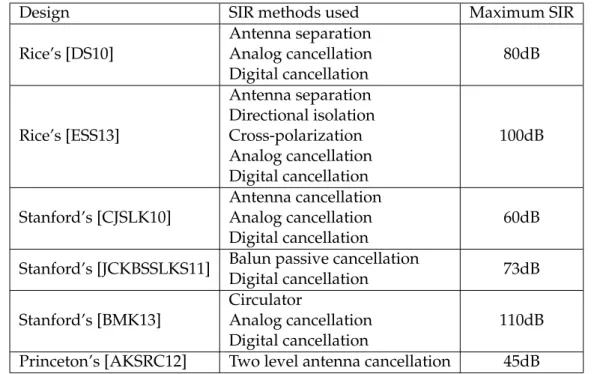
2.4.4 Comparison table
Table 2.2 shows a summary of the designs described and their reported performance. The first IB-FDX transceivers that were developed could only reduce SI by roughly 80dB. With recent advances the latest models manage to achieve around 100dB of total SIR.
Design SIR methods used Maximum SIR
Rice’s [DS10]
Antenna separation Analog cancellation Digital cancellation
80dB
Rice’s [ESS13]
Antenna separation Directional isolation Cross-polarization Analog cancellation Digital cancellation
100dB
Stanford’s [CJSLK10]
Antenna cancellation Analog cancellation Digital cancellation
60dB
Stanford’s [JCKBSSLKS11] Balun passive cancellation
Digital cancellation 73dB
Stanford’s [BMK13]
Circulator
Analog cancellation Digital cancellation
110dB
Princeton’s [AKSRC12] Two level antenna cancellation 45dB
2. RELATEDWORK 2.5. Full-duplex medium access control protocols
2.5
Full-duplex medium access control protocols
This section presents some of the FDX MAC protocols that have been developed by the scientific community. Most of the protocols proposed are additions and modifications of the current IEEE 802.11 standard. This is due mainly to the fact that it is easier to engineer a solution that can adapt to the current standard and allows backward compatibility. Carrier Sense Multiple Access (CSMA) with Collision Detection (CD) methods distin-guish themselves by being able to detect collisions in the medium and stop transmitting to save time and bandwidth. CD mechanisms are the basis of classic ethernet Local Area Network (LAN) and have satisfactory performance as long as it is possible to sense the entire medium.
In conventional wireless communication however, CD mechanisms do not work as well, since the range of a radio interface may not cover the entire system. Therefore, IEEE 802.11 establishes CSMA with Collision Avoidance (CA) as its MAC protocol. CA mech-anisms are quite similar to CD’s, except CA methods have backoff timers in order to avoid collisions and ACKnowledgement control packet (ACK) frames are used to infer collisions. In CSMA/CA collisions are undetectable, so the entire frame is transmitted even if a collision occurs [Tan10]. IB-FDX brings the possibility of using CSMA/CD in a wireless medium.
The protocols covered in this section can be sorted into two major groups: the ones that are optimized for single-hop networks and the ones that are optimized for multi-hop networks. Figure 2.14 depicts the two main types of topologies that can result from the adoption of IB-FDX at the network level: the relay and bidirectional topologies. Both topologies can be applied to either single-hop networks or multi-hop networks and have the potential to double the spectral efficiency and throughput.
Figure 2.14(a) depicts the relay topology, where nodeRacts as a relay for the single flow of data being sent from source nodeS to destination nodeD [SSGBRW14]. In HDX, 2 time slots are required for each packet to reach nodeD, whereas in FDX, every time slot can be used for nodeR to forward traffic without having to alternate between receiving from nodeS and transmitting to nodeD. For this scenario, only nodeR must possess IB-FDX capability. In a multi-hop network, the scenario presented in figure 2.14(a) can be extended in order to havenMTs relaying packets every time slot (provided all relays can operate in IB-FDX) as inS→R1→ · · · →Rn→D. This extension cannot be applied
in single-hop networks since the Base Station (BS) or the AP is always the central node in the system.
Figure 2.14(b) depicts the bidirectional topology, where two data flows are active (A→B
2. RELATEDWORK 2.5. Full-duplex medium access control protocols
Figure 2.14: IB-FDX at the network level. (a) relay topology; (b) bidirectional topology. Adapted from [SSGBRW14].
2.5.1 Medium access control protocols optimized for single-hop networks (In-frastructure)
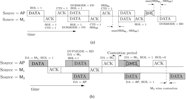
In a single-hop network, nodes communicate through a central AP. This means that the AP is always going to be either the source or the destination of the message being transmitted. This means that there can only be a maximum of two active flows at any given time [SPS11]. This assumption gives the AP the ability to control and regulate the other nodes’ communication process.
2.5.1.1 Rice’s Full-Duplex Medium Access Control
The Full-Duplex Medium Access Control (FD-MAC) [SPS11] uses the Rice’s FDX transceiver architecture covered in section 2.4.1.1. FD-MAC builds on IEEE 802.11 and adds three new mechanisms in order to fully capitalize from the benefits of FDX.
Mechanisms
1. Shared random backoff;
2. Header snooping;
3. Virtual contention resolution.
2. RELATEDWORK 2.5. Full-duplex medium access control protocols
Header snooping allows nodes to estimate the local topology. In order for this to work the nodes need to decode and examine the headers of all ongoing transmissions within radio range.
Virtual contention resolution’s goal is to maximize the amount of FDX flows by using simultaneous communication whenever possible. This is done by making the AP look through multiple packets in its buffer and statistically deciding the one it’s going to serve first.
Packet structure
Figure 2.15 depicts the FD-MAC’s packet structure. The packets structure from IEEE 802.11 is adopted, where the PHYsical layer (PHY) header, payload and Cyclic Redun-dancy Check (CRC) fields are not modified. The MAC header is divided in two separate headers: the IEEE 802.11 MAC header and a novel Full-Duplex (FD) header. The FD header is divided in 6 separate fields. DUPMODE is a one bit field to distinguish a FDX packet from a HDX packet (denoted as Full-Duplex (FD) and Half-Duplex (HD)). Head-Of-Line (HOL) is a one bit field to indicate that the next packet in the buffer is for the destination of the current packet. DURNXT and DURFD are both 2 bytes long and their goal is to reveal the duration of HOL packet and the duration of the FDX exchange respec-tively. These two fields are optional, but relevant to counter the hidden node problem. Clear-To-Send (CTS) is a one bit field that indicates that the destination of the current packet can send a packet to the source of the current packet. Lastly, the Shared Random Backoff (SRB) is a 10 bit field that indicates the common delay both nodes will wait before resuming FDX mode. Since both nodes transmit a packet with SRB field, the maximum value of the two is chosen.
Figure 2.15: FD-MAC’s packet structure. Adapted from [SPS11].
Timeline
2. RELATEDWORK 2.5. Full-duplex medium access control protocols
(a)
(b)
Figure 2.16: FD-MAC’s timeline of events. (a) bidirectional communication; (b) relay communication. Adapted from [SPS11].
an ACK in order to confirm the reception of the packet and setsHOL = 1andCTS = 1to inform the AP that it wants to initiate a FDX communication. The AP responds with an ACK withCTS = 1, allowing M1 to start transmitting. AP and M1 engage in FDX packet exchange and once the DATA packets finish, they both confirm the reception by broad-casting an ACK. In this case, both nodes still have more packets in queue for each other, but they need to give other nodes the opportunity to transmit. In order to assure this, the AP and M1 set a common backoff time, given by the maximum value of the SRB field of both nodes. This allows them to skip the first two steps of the protocol (contention reso-lution followed by the transmission of one HDX packet). After the shared backoff time, both engage in FDX communication again, but the AP’s ACK is not received properly by M1. This makes M1 purge its knowledge of the queue and contend for the medium at the end of two ACK periods after the DATA packet exchange finishes.
If the AP and the two MTs form a clique (M1 and M2 in radio range of each other), relay topology cannot be enabled due to the ITI. This concept will be covered with more detail in section 2.6. Therefore, figure 2.16(b) depicts FD-MAC’s timeline of events where M1 and M2 are outside of each other’s radio range since this is what allows them to engage in relay communications (AP → M1, M2 → AP andAP → M2, M1 → AP). In this example, M1 does not have packets in queue, therefore it is only receiving. For M2 to engage in a relay communication, two conditions have to be met:
1. M1 cannot be in radio range of M2;
2. RELATEDWORK 2.5. Full-duplex medium access control protocols
In order for M2 to ensure condition 1, it waits for one ACK duration after the finish of the DATA packet from AP. If M2 does not receive the ACK, it assumes that M1 is not in radio range.
In order for M2 to ensure condition 2, it decodes the FD header of the DATA packet being sent by the AP. Since DUPMODE = HD, M1 will not transmit and M2 can start transmitting its packet to AP. For this transmission, the packet has to be fragmented so that M2’s transmission ends before M1’s ACK begins. In this case, one of the DATA packets that AP sent to M1 was not received properly, so M1 does not respond with an ACK making backoff synchronization impossible. Therefore, both nodes purge the information about the queue state, which makes the protocol return to its initial state (contention resolution).
These two conditions allows MTs to engage in FDX communications with the AP, but may cause collisions if there are more MTs out of range of the AP’s destination. To solve this, each node that detects a FDX opportunity, only transmits its packet with probability
pi.
[SPS11] reports that FD-MAC achieves a throughput gain of up to 70% over HDX for identical transmit power.
2.5.1.2 Stanford’s Janus
Janus [KMQKL13] is a innovative new MAC protocol, specifically designed to exploit FDX wireless capabilities. This protocol’s notable traits are its ability to:
1. Identify all FDX opportunities;
2. Schedule packet exchange to maximize throughput;
3. Avoid collisions.
This protocol operates in cycles. At the beginning of each cycle, the AP broadcasts a probe packet. This packet signals all nodes registered under the AP to send the length of the packets they want to send. This exchange is done in a predefined order and allows the AP to identify the size of incoming packets and simultaneously collect information about the interference environment around each node. The interference information is stored in a table called conflict map and gives the AP an accurate picture of interference in the network, that allows it to identify which nodes can transmit simultaneously. After receiving this information, the AP calculates the best possible combination of trans-missions and the data rates of the transtrans-missions. This centralized mechanism allows the AP to schedule transmissions in a way that completely eliminates collisions and maxi-mizes throughput. This calculation is performed by the FDX scheduler using the infor-mation gathered by the replies of the MTs.
2. RELATEDWORK 2.5. Full-duplex medium access control protocols
The throughput with Janus can be up to 2.5 times higher than its HDX alternative [KMQKL13]. However, maintaining an optimized schedule may require too many network and pro-cessing resources in a dynamic network with fast moving terminals.
2.5.2 Medium access control protocols optimized for multi-hop networks (Ad-hoc)
A multi-hop network is a decentralised type of network, with no pre-existing infrastruc-ture, where each node participates in forwarding data for other nodes. The topology is assumed to be irregular and constantly changing.
2.5.2.1 Sophia’s University full-duplex medium access control protocol
[MB12] proposes a novel line-type multi-hop MAC protocol that uses directional anten-nas’ controllable directivity to mitigate interference. This type of scenario is highly ap-plicable in wireless mesh networks and wireless sensor networks. It uses Stanford’s FDX transceiver architecture covered in section 2.4.2.2.
This protocol intends to use FDX communication in order to enable relay switching, by creating a one-way flow of data traffic. An example of a operation using the proposed protocol is shown in figure 2.17.
Figure 2.17: Operation with proposed protocol. Adapted from [MB12].
It builds on CSMA/CA without Request To Send (RTS)/CTS with three main modifica-tions:
1. Modified condition for data transmission;
2. No acknowledgement frames;
2. RELATEDWORK 2.5. Full-duplex medium access control protocols
The data transmission condition is modified so that a node is allowed to transmit data if it detects carrier and the destination MAC address of the detected data is the node itself. This is what allows the nodes to engage in two-way simultaneous communications. The reason given for the removal of the acknowledgement frame was that since the protocol assumed sophisticated routing protocols or topology controls were used, the ACKs were redundant and only caused collisions. The last modification has to do with the fact that data collisions hardly occur in line-type multi-hop networks. Therefore, this mechanism was removed from the protocol.
This protocol does not address possible errors that might occur due to channel noise generated from other devices. Given the lack of ACKs, the errors have to be addressed by mechanisms at higher layers (e.g. transport). [MB12] focus heavily on preventing and avoiding collisions, rather than resolving them.
This article reports that the protocol presented can improve end-to-end throughput up to 114% in such systems.
2.5.2.2 Wisconsin-Madison’s full-duplex medium access control protocol
[XZ14] is an asynchronous MAC protocol. It allows a pair of FDX transceivers to contend for channel access and transmit packets independently, as if no mutual interference exists. This protocol builds on IEEE 802.11 standard, adding two specific features:
1. While in receiving mode, a receiver can continue sensing its channel status;
2. While in receiving mode, a receiver can transmit back to the sender if it senses an idle channel and finishes backoff.
With this protocol, it is not possible to synchronize the transmitter and receiver’s MAC operations, therefore they need to contend for channel access independently.
Unlike the other protocols described, this protocol does not try to maximize the amount of FDX opportunities. Therefore, two-way simultaneous communications only occurs if their transmissions happen to overlap. An example of an operation using the proposed protocol is shown in figure 2.18.
2. RELATEDWORK 2.6. Full-duplex and the inter-terminal interference
This article reports an average throughput with this protocol 1.46 times higher than its HDX alternative, but it can reach up to 2.5 times higher.
2.6
Full-duplex and the inter-terminal interference
[XZ14] reported that while FDX has the potential to double the data rate within the cell’s coverage range, having two MTs transmitting simultaneously translates into a wider in-terference region. This effect is shown in figure 2.19. This is called ITI and its representa-tion is illustrated in figure 2.19.
Unu sab le sp ace for other tran smissions o r receptions
T1 T2
Reu sab le sp ace for other tran smissions
Reu sab le sp ace for other receptions
T3 T4
(a)
Unu sab le sp ace for other tran smissions o r receptions
T1 T2
Unu sab le sp ace for other tran smissions o r receptions
Unu sab le sp ace for other tran smissions o r receptions
(b)
Figure 2.19: (a) spacial reuse for HDX; (b) spacial reuse for FDX. Adapted from [XZ14]
In HDX, since T1 is not receiving, other MTs can transmit inside its interference range. A similar concept applies to T2, as it is only receiving, other MTs can use that space to receive from other MTs. With FDX however, as both MTs are transmitting and receiving simultaneously, no other MTs are allowed to access the channel within their interference range.
2. RELATEDWORK 2.7. Multipacket reception
2.7
Multipacket reception
In a traditional communications system, simultaneous transmissions result in collisions, which degrade the network’s throughput. These systems are classified as Single Packet Reception (SPR), which implies that receivers can only receive a packet from each source at a time. A MPR system however, allows a node to receive more than one packet from multiple concurrent transmissions. This way, it is possible to decode the packets that were transmitted, even if a collision occurred [LSW12].
Figure 2.20: Classification of techniques applied for MPR. Adapted from [LSW12].
Many different technologies can be employed in order to enable MPR, classified in [LSW12]. Figure 2.20 divides MPR techniques into three main classes, which correspond to the place where the responsibility of enabling MPR lies. This classification is given based on transmitter, transreceiver, and receiver perspective.
2.7.1 Receiver perspective
The techniques used in this class completely shift the responsibility from the transmitters to the receivers [LSW12].
To employ the matching filter technique, the matched filter is calculated by correlating a known signal, or template, with an unknown signal to detect the presence of the template in the unknown signal [Doy09]. This technology is used extensively for SPR [LSW12], but its principles can also be applied to MPR, as in [CLBK04] where it is assumed that radio receivers devices are made of a bank of match filters that are able to decode each spread-ing code individually. This allows the receiver to receive packets concurrently from mul-tiple sources without the need of having orthogonal spreading codes.
2. RELATEDWORK 2.7. Multipacket reception
in order to enable MPR as it lessens Multiple Access Interference (MAI) during the si-multaneous transmissions on the same channel [LSW12]. A drawback to MUD is the requirement that the spreading codes of the multiple transmitters are known to the re-ceivera priori[Mos96].
MUD can be optimal or sub-optimal. Optimal MUD, despite being a excellent at demod-ulating the junction of multiple signals, has proven to be too computationally complex, increasing its complexity exponentially with the number of active users [Ver89]. There-fore, the scientific community has designed sub-optimal MUD techniques, that have a comparable performance relative to optimal MUD, but are computationally simpler. Sub-optimal MUD schemes can be divided into two categories: linear and non-linear.
In linear MUD, a linear transformation is applied to the soft outputs of the conventional detector, producing a new set of outputs, which are likely to have a better performance [Mos96]. Non-linear MUD schemes rely on interference estimators to remove the inter-ference from the received signal before detection. Linear detectors should always achieve better results than non-linear detectors, but makes for a much more complex system [LSW12].
Nonlinear techniques can be divided in successive and Parallel Interference Cancella-tion (PIC). For this dissertaCancella-tion, successive interference cancellaCancella-tion will be referred as MultiPacket Reception by successive Interference Cancellation (MPR-IC). In MPR-IC it is required that the signals’ power received at a given MT have enough separation be-tween them. If this occurs, the concurrent transmissions are demodulated and cancelled allowing the serial resolution from the signal with the highest power to the one with the lowest power [XPWCL13; GDBO12]. On the other hand, PIC uses an estimate from the interfering bits from previous stages in order to enable the resolution of multiple packets [LSW12]. According to [LSW12], while PIC could support more simultaneous packets from different users it requires perfect power control, making MPR-IC a much simpler and practical solution in order to enable MPR.
2.7.2 Transmitter perspective
This set of techniques uses the transmitter as the critical piece in order to enable MPR. Techniques in this class revolve around separating different signals into orthogonal sig-nalling dimensions in order to allow channels to be shared by multiple users. This is called multiplexing and the most used in MPR are frequency and code division multi-plexing.
2. RELATEDWORK 2.7. Multipacket reception
[BTFRM08].
Code Division Multiple Access (CDMA) is a form of spread spectrum communication in which a narrowband signal is spread out over a wider frequency band, allowing each user to transmit over the entire frequency spectrum all the time [Tan10]. For this, each bit time is subdivided intomshort intervals called chips and each node is assigned a unique
m-bit code called a chip sequence, known to the receivera priori. During each bit time a node can transmit a 1 bit by sending its chip sequence and a 0 bit by sending the negation of its chip sequence. In order to resolve the content of the message, the receiver computes the normalized inner product between the received chip sequence and the chip sequence of the station it wants to receive [Tan10].
2.7.3 Transreceiver perspective
Techniques in this class are hybrid in the sense that use cooperation between transmitters and receivers in order to enable MPR. There are 4 main types of techniques that can be employed in this class: multi-antenna MIMO, signal separation, polynomial phase se-quence and resource allocation. This dissertation will focus on resource allocation tech-niques since a variation of these methods is implemented in the presented system. Network-assisted Diversity Multiple Access (NDMA) was first introduced in [TZB00] and it relied on storing collided packets in memory rather than being discarded. These packets are later combined with users’ retransmissions in order to extract the collided information packets. Since this approach spreads the packet in time, it will be referred in this dissertation as MultiPacket Reception by Time diversity (MPR-T).
In NDMA [TZB00], for a collision of k users, k time slots are required to resolve the collision, therefore no channel slot is lost when a collision takes place. For this tech-nique, it is mandatory that all users in the system possess a unique orthogonal IDenti-fication (ID). This causes bandwidth inefficiency, especially with large user populations [TZB00]. This mechanism provided a novel signal processing-oriented viewpoint to the random medium access problem [TZB00] and was soon extended to several variants. In [MV05] the Feedback-Free Network-assisted Diversity Multiple Access (FF-NDMA) was proposed which classified as a version of NDMA for uncoordinated ad-hoc net-works. It was shown that retransmission diversity could improve the efficiency of ran-dom access, either in terms of energy, connectivity or bandwidth efficiency [MV05]. In [ZST02] a blind collision resolution scheme called Blind Network-assisted Diversity Multiple Access (B-NDMA) was presented. Blind techniques differ from original NDMA by removing NDMA’s orthogonal sequence requirement. For this, an extra retransmis-sion relative to training-based NDMA is necessary, but reduces packet length for the payload. This results in improved channel utilization and system capacity (especially with large user populations). B-NDMA determines the multiplicity by using a rank test method and resolves the packets by employing parallel factor analysis [ZST02].
![Figure 2.2: SI reducing methods. Adapted from [SPDS13].](https://thumb-eu.123doks.com/thumbv2/123dok_br/16584782.738713/35.892.280.652.418.683/figure-si-reducing-methods-adapted-from-spds.webp)
![Figure 2.10: Block diagram of the transceiver. Adapted from [CJSLK10].](https://thumb-eu.123doks.com/thumbv2/123dok_br/16584782.738713/42.892.161.682.129.533/figure-block-diagram-transceiver-adapted-cjslk.webp)
![Figure 2.11: Block diagram of the transceiver. Adapted from [JCKBSSLKS11].](https://thumb-eu.123doks.com/thumbv2/123dok_br/16584782.738713/43.892.191.736.133.570/figure-block-diagram-transceiver-adapted-jckbsslks.webp)
![Figure 2.12: Block diagram of the transceiver. Adapted from [BMK13].](https://thumb-eu.123doks.com/thumbv2/123dok_br/16584782.738713/44.892.220.627.134.595/figure-block-diagram-transceiver-adapted-bmk.webp)

![Figure 2.20: Classification of techniques applied for MPR. Adapted from [LSW12].](https://thumb-eu.123doks.com/thumbv2/123dok_br/16584782.738713/54.892.109.743.336.590/figure-classification-techniques-applied-mpr-adapted-lsw.webp)
![Figure 2.21: H-NDMA’s reception scheme. Adapted from [GPBDOP13].](https://thumb-eu.123doks.com/thumbv2/123dok_br/16584782.738713/58.892.118.717.135.422/figure-h-ndma-reception-scheme-adapted-from-gpbdop.webp)
