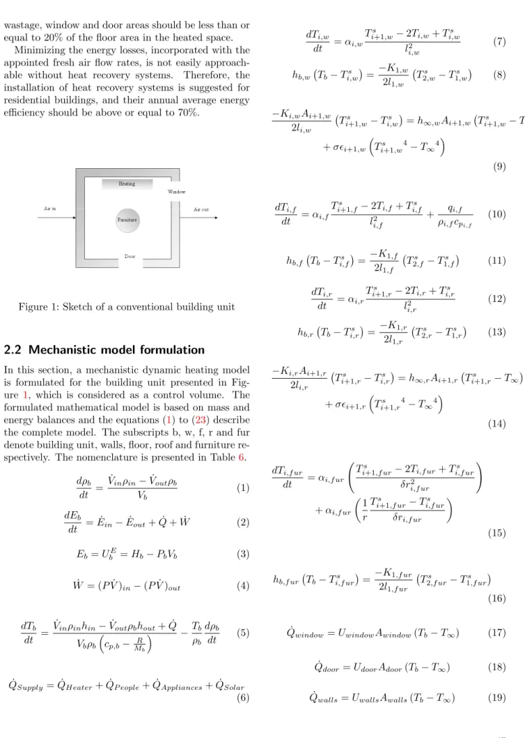
Modelling the heat dynamics of a residential building unit: Application to Norwegian buildings
Texto
Imagem


Documentos relacionados
Este trabalho vai evidenciar assim um obus 155mm do tipo Lightweight, como uma hipótese para equipar o sistema de apoio de fogos de um GAC orgânico da Brigada de
O objetivo geral é compreender o que significa bem-estar psicológico para as pessoas idosas, que experienciam um envelhecimento bem-sucedido. As questões de
Cada região possui características próprias que podem impactar na dinâmica dos agravos, assim como as especificidades para as variáveis raça/cor, sexo e escolaridade dos
Os resultados mostram que o tema é apresentado de forma satisfatória nos livros didáticos, apontam uma relação significativa destes com as provas do ENEM e permitem reflexões sobre
The probability of attending school four our group of interest in this region increased by 6.5 percentage points after the expansion of the Bolsa Família program in 2007 and
Na maioria das sequências de jogo, podemos encontrar : (i) um primeiro toque, que se destina ao controlo da bola, proveniente do campo adversário, através da acção de recepção
Além disso, o Facebook também disponibiliza várias ferramentas exclusivas como a criação de eventos, de publici- dade, fornece aos seus utilizadores milhares de jogos que podem
As principais condições de contaminação de aquíferos são: O processo natural de precipitação e infiltração pode implicar a contaminação de águas subterrâneas
