COORDINATED AND OPTIMIZED VOLTAGE MANAGEMENT
OF DISTRIBUTION NETWORKS WITH MULTI-MICROGRIDS
André Guimarães Madureira
(MSc)
Dissertation submitted to the Faculty of Engineering of University of Porto
in partial fulfilment of the requirements for the degree of
Doctor of Philosophy
Dissertation Supervisor: Prof. João Abel Peças Lopes Full Professor at the
Department of Electrical and Computer Engineering Faculty of Engineering, University of Porto
This work was supported in part by FCT – Fundação para a Ciência e a Tecnologia de
Portugal, under the grant SFRH/BD/29459/2006, and by INESC Porto – Instituto de
Engenharia de Sistema e Computadores do Porto.
Acknowledgment
This work could not have succeeded if it was not for the help and contribution of several people. I hope I can do them justice and not forget anyone. Anyway, they know who they are. First of all, I would like to thank my supervisor, Prof. João Peças Lopes. It has been my privilege to work closely with him since 2004 and it has been quite a journey since then. During these years of PhD work, he has been the beacon that kept shining when storm was raging, keeping me out of dangerous waters. His knowledge and guidance but also his dedication, commitment and especially his enthusiasm have been crucial in the making of this thesis and I could not be more grateful.
I would also like to thank Prof. Manuel Matos for his support and encouragement and particularly for his useful insights on multi-criteria decision aid in several discussions we had. I would like to acknowledge the important contribution of my colleagues at INESC Porto that have worked with me in the MicroGrids and More MicroGrids projects, particularly Carlos Moreira but also Nuno Gil and Fernanda Resende. During all these years I have been learning a lot from our close collaboration, namely through fruitful discussions.
More thanks are due to the people who have worked with me in the Power Systems Unit of INESC Porto since 2004, especially Luís Seca, Rute Ferreira, Paula Castro, Jorge Pereira, Ricardo Ferreira, Mauro Rosa, Hrvoje Keko, Ricardo Bessa, André Moreira, Pedro Almeida, Julija Vasiljevska, Joel Soares, Leonel Carvalho, Diego Issicaba, Bernardo Silva and Ricardo Rei. All of them have contributed in several different and invaluable ways to the success of this work and I am grateful for their support and friendship.
The support of my family and friends has been so precious during these sometimes difficult times. From the bottom of my heart, thank you all.
Thank you to my parents, Carlos and Margarida, for making me who I am today. You have always believed in me even when I doubted myself. I can never repay you enough. I know that I will never learn so much as I do from you both, everyday and in every way.
Thank you to my sister Cristina who has raced with me on this PhD quest. The one time I am proud of coming second-best. I am glad I could have you next to me sharing all the distresses and happy times. Also, thank you to my nephews Afonso, Vasco e Francisco for sometimes taking me away from the dreaded claws of PhD work.
Thank you to my uncle Jorge who helped me in the final stages of printing the document. Thank you to my closest friends, especially Tadeu, who has always been there and believed in me. You should know that I could not have done it without you.
Finally, very special thanks are due to my very special one: Sara. For all the love, support, care, patience and encouragement you have shown me, which I can barely describe in words. You truly are my inspiration. This work was done really at your expense, from the time I could not spend with you to the constant bad moods you had to endure.
Abstract
This thesis presents a set of proposals for advanced control functionalities in order to achieve a coordinated and optimized voltage management of distribution networks comprising several Distributed Generation units, controllable loads, storage devices and microgrids.
The approach followed here is based on the exploitation and extension of the microgrid concept following a massive integration of these “active cells” in electrical distribution networks. Therefore, a hierarchical control architecture is proposed in order to manage all these Distributed Energy Resources located in the distribution system in a coordinated way, based on advanced communication solutions exploiting a smart metering infrastructure. This control structure is characterized by the inclusion of an additional controller at the Medium Voltage level – the Central Autonomous Management Controller – leading to the development of the Multi-Microgrid concept.
Large scale integration of Distributed Energy Resources, namely Distributed Generation at the Medium Voltage level and microgeneration at the Low Voltage level, poses several technical challenges for distribution network operation, especially concerning voltage control. Accordingly, the development of specific control solutions is required in order to maximize the integration of these units in the distribution system.
Consequently, the work presented in this thesis focused on the development of a conceptual framework model for regional ancillary services markets for voltage control. The approach developed is able to integrate the reactive power bids from the several providers (namely Distributed Generation units or microgrids) in order to satisfy the requested reactive power needs at the Medium Voltage level, which are set by the Distribution System Operator. The market settlement is achieved based on cost minimization for the Distribution System Operator from purchasing reactive power. An ancillary services market simulator for reactive power use was developed implementing this approach for a medium-term time horizon using data from generation scheduling and renewable generation and load forecasts.
Finally, a methodology for voltage and reactive power control to be integrated in a tool for managing network operation in the short-term time-horizon has also been developed. This approach was developed in order to ensure a coordinated operation concerning the Medium Voltage and Low Voltage levels, by managing the several resources available such as Distributed Generation units, microgrids, controllable loads, On-Line Tap Changing transformers and other reactive power compensation devices. A meta-heuristic approach is used in order to optimize operating conditions. An Artificial Neural Network model has also been developed in order to replace “active” Low Voltage networks in the optimization module, making it suitable for online use in a real-time management environment.
Resumo
Nesta tese apresenta-se um conjunto de propostas com vista ao desenvolvimento de funcionalidades avançadas de controlo de forma a garantir uma gestão coordenada e optimizada de redes de distribuição de energia eléctrica incluindo diversas unidades de Produção Distribuída, cargas controláveis, dispositivos de armazenamento de energia e micro-redes.
A abordagem seguida baseia-se na exploração e extensão do conceito de micro-rede na sequência de uma integração maciça destas “células activas” nas redes de distribuição. Neste sentido, propõe-se o estabelecimento de uma arquitectura hierárquica de controlo capaz de gerir todos estes recursos distribuídos localizados no sistema de distribuição de uma forma coordenada, com base em soluções avançadas de comunicação que exploram uma infra-estrutura para tele-contagem de energia eléctrica. Esta infra-estrutura de controlo é caracterizada pela inclusão de um controlador adicional ao nível da Média Tensão – o Controlador Central Autónomo de Gestão – que levou ao desenvolvimento do conceito de multi micro-rede. A integração em larga escala de recursos distribuídos, nomeadamente Produção Distribuída ao nível da Média Tensão e micro-geração ao nível da Baixa Tensão, levanta diversos desafios técnicos para a operação da rede de distribuição, especialmente relativo ao controlo de tensão. Desta forma, torna-se necessário desenvolver soluções específicas de controlo de forma a maximizar a integração destas unidades no sistema de distribuição.
Consequentemente, o trabalho apresentado nesta tese foca-se no desenvolvimento de um modelo conceptual para a implementação de mercados regionais de serviços de sistema para controlo de tensão. A abordagem desenvolvida permite integrar as propostas de energia reactiva dos vários fornecedores (nomeadamente unidades de Produção Distribuída e micro-redes) de forma a satisfazer os requisitos de energia reactiva ao nível da Média Tensão, fixados pelo Operador do Sistema de Distribuição. O fecho do mercado é atingido baseado na minimização dos custos de compra desta energia para o Operador de Sistema. Baseado nesta abordagem, foi desenvolvido um simulador de mercado de serviços de sistema para controlo de tensão para um horizonte temporal de médio-prazo, utilizando informação proveniente do despacho de geração e de ferramentas de previsão de carga e de produção de recursos renováveis.
Desenvolveu-se ainda uma metodologia para o controlo de tensão e potência reactiva destinada a ser integrada numa ferramenta para um horizonte temporal de curto-prazo para ajuda à operação da rede. Esta metodologia foi desenvolvida de forma a garantir um controlo coordenado ao nível da Média Tensão e da Baixa Tensão através da gestão dos vários recursos disponíveis tais como unidades de Produção Distribuída, micro-redes, cargas controláveis, transformadores com regulação em carga e outros dispositivos de compensação de energia reactiva. A abordagem desenvolvida baseou-se na utilização de uma meta-heurística de forma a optimizar as condições de operação. Adicionalmente, foi desenvolvido um modelo de uma Rede Neuronal capaz de emular o comportamento em regime estacionário de redes “activas” de Baixa Tensão, modelo esse que foi integrado no módulo de optimização de forma a permitir a sua utilização em ambiente de operação em tempo-real.
Table of Contents
List of Figures ... 15
List of Tables ... 19
List of Acronyms and Abbreviations... 21
Chapter 1 – Introduction ... 25
1.1 Motivation for the Thesis ... 25
1.2 Objectives of the Thesis ... 30
1.3 Outline of the Thesis ... 30
Chapter 2 – State-of-the-Art ... 33
2.1 Distributed Generation and Active Network Management ... 33
2.1.1 Introduction ... 33
2.1.2 The Distributed Generation Concept ... 35
2.1.3 Main Distributed Generation and Storage Technologies ... 38
2.1.4 Drivers and Challenges for Distributed Generation Growth ... 42
2.1.5 Distributed Generation Siting ... 45
2.1.6 Active Distribution Network Management ... 46
2.2 Microgeneration and Microgrid Systems ... 48
2.2.1 Introduction ... 48
2.2.2 The CERTS Microgrid Concept ... 50
2.2.3 The EU Microgrid Concept ... 53
2.2.4 Advantages and Challenges of Microgrids ... 55
2.2.5 The Microgrid in the General Smartgrid Concept ... 57
2.3 Voltage Regulation ... 59
2.3.1 Introduction ... 59
2.3.2 Voltage Control in Distribution Networks with Distributed Generation ... 61
2.3.3 Control of Power Electronic Interfaced Distributed Generation... 64
2.4.1 Introduction ... 67
2.4.2 Ancillary Services from Distributed Generation and Microgrids ... 68
2.4.3 Ancillary Services Markets ... 72
2.5 Summary and Main Conclusions ... 74
Chapter 3 – Novel Concepts for Distribution Network Architecture ... 77
3.1 Introduction ... 77
3.2 The European Project “More MicroGrids” ... 78
3.3 Multi-Microgrid Control and Management Architecture ... 81
3.4 Hierarchical Control Approach ... 83
3.4.1 Interactions among Controllers and Data Flows ... 84
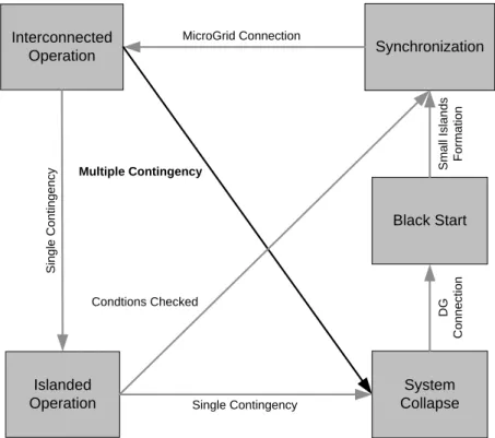
3.4.2 Operating Modes ... 85
3.5 Decentralized Control Approach ... 87
3.6 Central Autonomous Management Controller Functionalities ... 88
3.6.1 Voltage/var Support ... 89
3.6.2 Control Scheduling (Markets) ... 91
3.7 Summary and Main Conclusions ... 93
Chapter 4 – Coordinated Voltage Support ... 95
4.1 Introduction ... 95
4.2 Mathematical Formulation ... 96
4.2.1 Medium Voltage Network Control ... 98
4.2.2 Low Voltage Network Operation ... 99
4.2.3 Control Variables ... 101
4.2.4 Objective Function ... 101
4.2.5 Constraints ... 102
4.3 Development of the Approach... 104
4.3.1 Optimization Algorithm ... 104
4.3.3 Artificial Neural Networks ... 111
4.3.4 Development of the Tool ... 120
4.3.5 Integration of the Voltage Control Module ... 122
4.4 Summary and Main Conclusions... 123
Chapter 5 – Ancillary Services Market for Voltage Control ... 125
5.1 Introduction ... 125
5.2 Mathematical Formulation ... 129
5.2.1 Participation in Voltage Control Services ... 130
5.2.2 Market Proposal for Voltage Control ... 132
5.2.3 Market Players... 133
5.2.4 Market Bids ... 133
5.2.5 Objective Function ... 134
5.2.6 Constraints ... 134
5.3 Development of the Approach ... 136
5.3.1 Optimization Algorithm ... 136
5.3.2 Microgrid Policies ... 137
5.3.3 Scenario Definition and var Demand ... 139
5.3.4 Development of the Tool ... 140
5.3.5 Integration of the Ancillary Services Market Module ... 142
5.4 Summary and Main Conclusions... 143
Chapter 6 – Main Results ... 145
6.1 Test Networks ... 145
6.1.1 Medium Voltage Networks ... 145
6.1.2 Low Voltage Networks ... 147
6.2 Low Voltage Network Model ... 150
6.2.1 Artificial Neural Network Performance ... 151
6.3.1 Initial Considerations ... 155
6.3.2 Multi-Objective Decision Aid Analysis ... 157
6.3.3 Performance of the Algorithm ... 160
6.4 Ancillary Services Market for Voltage Control ... 181
6.4.1 Initial Considerations ... 181
6.4.2 Performance of the Algorithm ... 182
6.5 Summary and Main Conclusions ... 191
Chapter 7 – Conclusion ... 193
7.1 Main Contributions of the Thesis ... 193
7.2 Future Perspectives ... 195
References ... 199
Appendix A – Power Flow in Four-Wire Distribution Networks ... 207
Appendix B – Test Network Data ... 211
B-1 Medium Voltage Network 1 ... 211
B-2 Medium Voltage Network 2 ... 219
B-3 Low Voltage Network 1 ... 222
B-4 Low Voltage Network 2 ... 225
B-5 Low Voltage Network 3 ... 228
Appendix C – Load and Generation Scenarios ... 233
C-1 Combined Heat and Power Generation Unit Profile ... 233
C-2 Doubly-Fed Induction Generators Profile ... 233
C-3 Photovoltaic Microgeneration Units Profile ... 234
List of Figures
Figure 1-1 – Electricity Generation from Renewable Sources in Europe ... 26
Figure 1-2 – Technical and Economical Approaches for Voltage and Reactive Power Control .. 29
Figure 2-1 – Organization of Conventional Electrical Power Systems (adapted from [7]) ... 33
Figure 2-2 – Organization of Electrical Power Systems with Distributed Generation ... 35
Figure 2-3 – Relative Levels of System Capacity under Centralized and Distributed Control Strategies (adapted from [27])... 47
Figure 2-4 – CERTS Microgrid Architecture (adapted from [33]) ... 52
Figure 2-5 – “MicroGrids Project” Microgrid Architecture (adapted from *4+) ... 54
Figure 2-6 – Smart Power Networks [40] ... 59
Figure 2-7 – Voltage Variation down a Radial Feeder (adapted from [7]) ... 60
Figure 2-8 – Voltage Variation down a Radial Feeder for Several DG Penetration Scenarios .... 62
Figure 2-9 – Active Power/Frequency and Reactive Power/Voltage Droops [58] ... 65
Figure 3-1 – Control and Management Architecture of a Multi-Microgrid System... 78
Figure 3-2 – Communication Scheme of a Multi-MicroGrid System ... 82
Figure 3-3 – Control Scheme of a Multi-MicroGrid System ... 83
Figure 3-4 – Data Exchange between the CAMC, the MGCC, MV Loads and DG Units (adapted from [78]) ... 85
Figure 3-5 – Data Exchange between the MGCC and Local Controllers (adapted from [66]) .... 85
Figure 3-6 – Multi-Microgrid State Diagram ... 86
Figure 3-7 – CAMC Functionalities ... 89
Figure 3-8 – Hierarchical Voltage Control ... 90
Figure 4-1 – Example System ... 99
Figure 4-2 – Movement of a Particle in EPSO ... 107
Figure 4-3 – Common Penalty Functions for EPSO ... 108
Figure 4-4 – EPSO Algorithm ... 109
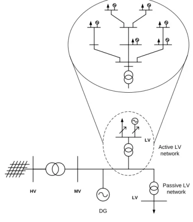
Figure 4-5 – Decoupled Modelling Approach used for the MV and LV Networks ... 110
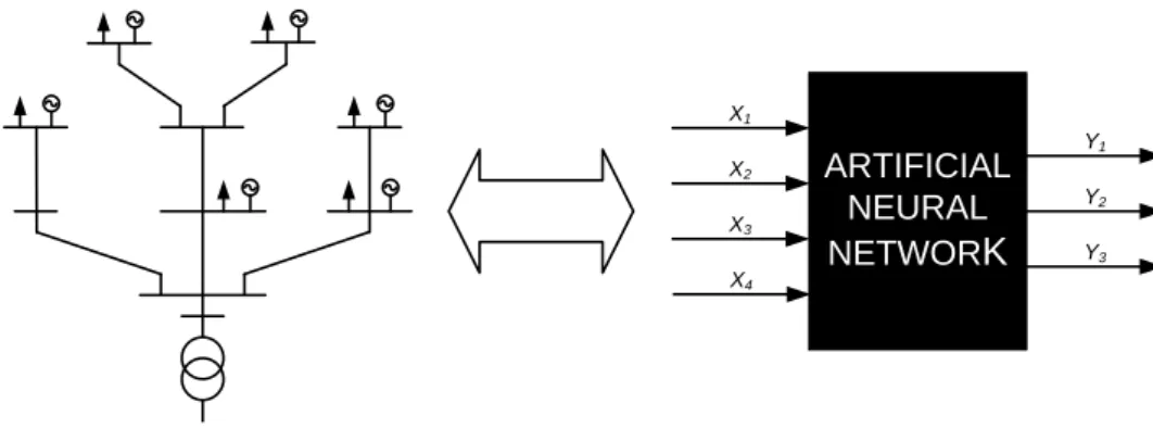
Figure 4-6 – Replacing an Active LV Network (Microgrid) by an ANN equivalent ... 111
Figure 4-7 – Scheme of a Basic Processing Unit (Neuron) in an ANN ... 112
Figure 4-8 –Common Activation Functions for ANNs ... 113
Figure 4-9 – Typical Structure of a Feed-Forward ANN ... 113
Figure 4-10 – ANN Training Process ... 114
Figure 4-11 – Artificial Neural Network for Microgrid Emulation ... 115
Figure 4-12 – ANN Structure ... 116
Figure 4-13 – Randomly Generated Points (One-Dimension)... 118
Figure 4-14 – Voltage/var Control Algorithm... 121
Figure 4-15 – Voltage Control Module included in the CAMC ... 122
Figure 5-1 – VPP Concept from a Technical Perspective and from a Market Perspective (adapted from [91]) ... 127
Figure 5-2 – Day-Ahead Market Structure for Voltage Control for each Hour ... 132
Figure 5-3 – var Bids (Including 3 Capacity Blocks Offered) ... 134
Figure 5-4 – Overview of the var Market Proposal ... 141
Figure 6-1 – MV Network 1 ... 146
Figure 6-2 – MV Network 2 ... 147
Figure 6-3 – LV Network 1 ... 148
Figure 6-4 – LV Network 2 ... 149
Figure 6-5 – LV Network 3 ... 150
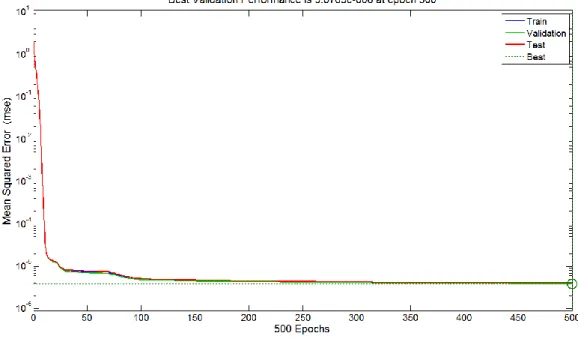
Figure 6-6 – MSE for Train, Validation and Test Sets following Training of ANN 1 ... 151
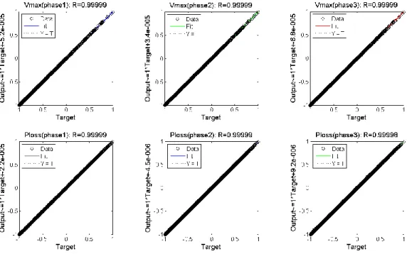
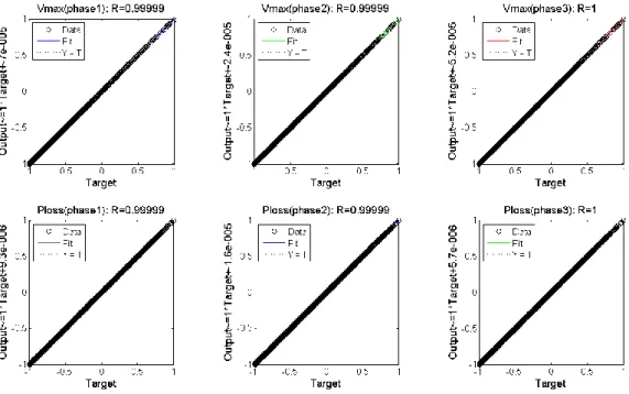
Figure 6-7 – Linear Regression of Targets relative to Outputs of ANN 1 ... 152
Figure 6-8 – MSE for Train, Validation and Test Sets following Training of ANN 2 ... 153
Figure 6-9 – Linear Regression of Targets relative to Outputs of ANN 2 ... 153
Figure 6-10 – MSE for Train, Validation and Test Sets following Training of ANN 3 ... 154
Figure 6-11 – Linear Regression of Targets relative to Outputs of ANN 3 ... 154
Figure 6-12 – Microgeneration Shedding vs. Active Power Losses ... 158
Figure 6-13 – Active Power Losses as a Function of the Decision Parameter ... 159
Figure 6-14 – Microgeneration Shedding as a Function of the Decision Parameter ... 159
Figure 6-15 – Evolution of the Fitness Function for Five Independent Runs ... 160
Figure 6-16 – Evolution of the Fitness Function for One Typical Run ... 161
Figure 6-17 – Evolution of the Active Power Losses ... 161
Figure 6-18 – Evolution of the Microgeneration Shedding ... 162
Figure 6-19 – Evolution of the Maximum Voltage in the MV Network ... 163
Figure 6-20 – Maximum Voltage in Microgrid 1 and Microgrid 2 ... 163
Figure 6-21 – Evolution of the Microgeneration Shedding using ANN Feeder Models ... 165
Figure 6-22 – Maximum Voltage in each Feeder of Microgrid 1 using ANN Feeder Models .... 166
Figure 6-23 – Maximum Voltage in each Feeder of Microgrid 2 using ANN Feeder Models .... 166
Figure 6-24 – Total Active Power Losses in the MV Network ... 168
Figure 6-25 – Maximum Voltage Values in the MV Network ... 168
Figure 6-26 – OLTC Transformer Tap Values ... 169
Figure 6-27 – Reactive Power from the CHP Unit ... 170
Figure 6-28 – Reactive Power from the DFIG 1 Unit ... 170
Figure 6-29 – Reactive Power from the DFIG 2 Unit ... 171
Figure 6-30 – Maximum Voltage Values in Microgrid 1 ... 171
Figure 6-31 – Maximum Voltage Values in Feeder 1 of Microgrid 1 ... 172
Figure 6-32 – Maximum Voltage Values in Feeder 2 of Microgrid 1 ... 172
Figure 6-33 – Maximum Voltage Values in Feeder 3 of Microgrid 1 ... 173
Figure 6-34 – Total Active Power Generation in Microgrid 1 ... 173
Figure 6-35 – Total Active Power Generation in Feeder 1 of Microgrid 1 ... 174
Figure 6-36 – Total Active Power Generation in Feeder 2 of Microgrid 1 ... 174
Figure 6-37 – Total Active Power Generation in Feeder 3 of Microgrid 1 ... 175
Figure 6-38 – Maximum Voltage Values in Feeder 1 of Microgrid 3 ... 175
Figure 6-39 – Maximum Voltage Values in Feeder 2 of Microgrid 3 ... 176
Figure 6-40 – Maximum Voltage Values in Feeder 3 of Microgrid 3 ... 176
Figure 6-41 – Maximum Voltage Values in Feeder 4 of Microgrid 3 ... 177
Figure 6-42 – Maximum Voltage Values in Feeder 5 of Microgrid 3 ... 177
Figure 6-43 – Total Active Power Generation in Feeder 1 of Microgrid 3 ... 178
Figure 6-46 – Total Active Power Generation in Feeder 4 of Microgrid 3 ... 179
Figure 6-47 – Total Active Power Generation in Feeder 5 of Microgrid 3 ... 180
Figure 6-48 – Maximum Voltage Values in Microgrid 5 ... 180
Figure 6-49 – Total Active Power Generation in Microgrid 5 ... 181
Figure 6-50 – Results from the Market Settlement (“Good-citizen” Policy) for the Valley Hour ... 184
Figure 6-51 – Results from the Market Settlement (“Ideal-citizen” Policy) for the Valley Hour ... 185
Figure 6-52 – Selected Bids (“Good-citizen” Policy vs. “Ideal-citizen” Policy) for the Valley Hour ... 185
Figure 6-53 – Results from the Market Settlement (“Good-citizen” Policy) for the Peak Hour 189 Figure 6-54 – Results from the Market Settlement (“Ideal-citizen” Policy) for the Peak Hour 189 Figure 6-55 – Selected Bids (“Good-citizen” Policy vs. “Ideal-citizen” Policy) for the Peak Hour ... 190
Figure A-1 – Three-phase Four-wire Line Section (adapted from [125]) ... 207
Figure A-2 – Model of the Three-phase Four-wire Multi-grounded Distribution Line (adapted from [125]) ... 208 Figure B-1 – MV Network 1 ... 211 Figure B-2 – MV Network 2 ... 219 Figure B-3 – LV Network 1 ... 222 Figure B-4 – LV Network 2 ... 225 Figure B-5 – LV Network 3 ... 228
Figure C-1 – 24-hours Generation Profile for CHP Unit ... 233
Figure C-2 – 24-hours Generation Profile for DFIG Unit ... 233
Figure C-3 – 24-hours Generation Profile for PV Unit ... 234
List of Tables
Table 2-1 – Main Distribution Generation Technologies ... 38
Table 2-2 – Possible Microgrid Architectures and their Characteristics ([29] and personal research) ... 50
Table 3-1 – DG Technological Capabilities for Ancillary Services Provision ... 93
Table 4-1 – Range and Resolution for Variable Sampling ... 119
Table 5-1 – Remuneration Alternatives for var Capacity and var Use ... 133
Table 6-1 – EPSO Parameters ... 156
Table 6-2 – Penalty Functions ... 156
Table 6-3 – Scenario for Load and Generation ... 158
Table 6-4 – Microgeneration Shedding required in each LV Network ... 162
Table 6-5 – Maximum Voltage Values Before and After the Voltage Control Algorithm ... 164
Table 6-6 – Comparison between Three-phase Power Flow Results and ANN Results for the Best Solution Found ... 164
Table 6-7 – Microgeneration Shedding required in each LV Network using ANN Feeder Models ... 167
Table 6-8 – Scenario for Load and Generation ... 167
Table 6-9 – Generation Scheduling for the Valley Hour ... 183
Table 6-10 – Reactive Power Bids for the var Market (“Good-citizen”) for the Valley Hour .... 183
Table 6-11 – Reactive Power Bids for the var Market (“Ideal-citizen”) for the Valley Hour... 184
Table 6-12 – Bids and Prices (“Good-citizen”) for the Valley Hour ... 186
Table 6-13 – Bids and Prices (“Ideal-citizen”) for the Valley Hour ... 186
Table 6-14 – Results from the OPF-like algorithm for the Valley Hour ... 186
Table 6-15 – Generation Scheduling for the Peak Hour ... 187
Table 6-16 – Reactive Power Bids for the var Market (“Good-citizen”) for the Peak Hour ... 187
Table 6-17 – Reactive Power Bids for the var Market (“Ideal-citizen”) for the Peak Hour... 188
Table 6-18 – Bids and Prices (“Good-citizen”) for the Peak Hour ... 190
Table 6-19 – Bids and Prices (“Ideal-citizen”) for the Peak Hour ... 190
Table 6-20 – Results from the OPF-like algorithm for the Peak Hour ... 191
Table B-1 – Line Data for MV Network 1 ... 212
Table B-2 – Transformer Data for MV Network 1 ... 216
Table B-3 – Load Data for MV Network 1 ... 216
Table B-4 – Generation Data for MV Network 1 ... 218
Table B-5 – Line Data for MV Network 2 ... 219
Table B-6 – Transformer Data for MV Network 2 ... 220
Table B-7 – Load Data for MV Network 2 ... 221
Table B-8 – Generation Data for MV Network 2 ... 221
Table B-9 – Line Data for LV Network 1 ... 222
Table B-10 – Load Data for LV Network 1 ... 223
Table B-11 – Generation Data for LV Network 1 ... 223
Table B-12 – Line Data for LV Network 2 ... 225
Table B-13 – Load Data for LV Network 2 ... 226
Table B-16 – Load Data for LV Network 3 ... 230 Table B-17 – Generation Data for LV Network 3 ... 231
List of Acronyms and Abbreviations
AC – Alternate Current
AGC – Automatic Generation Control ANN – Artificial Neural Network AVR – Automatic Voltage Regulator
CAMC – Central Autonomous Management Controller CCGT – Combined Cycle Gas Turbines
CERTS – Consortium for Electric Reliability Technology Solutions CHP – Combined Heat and Power
CIGRE – International Council on Large Electric Systems CIRED – International Conference on Electricity Distribution CO2 – Carbon Dioxide
DC – Direct Current
DER – Distributed Energy Resources DFIG – Doubly-Fed Induction Generation DG – Distributed Generation
DMS – Distribution Management System DSM – Demand Side Management DSO – Distribution System Operator EC – European Commission
ENTSO-E – European Network of Transmission System Operators for Electricity EPSO – Evolutionary Particle Swarm Optimization
ES – Evolutionary Strategies ETS – Emission Trading System EU – European Union
EURELECTRIC – Union of the Electricity Industry GHG – Green House Gases
HV – High Voltage
ICT – Information and Communication Technology IEA – International Energy Agency
IEE – Institution of Electrical Engineers
IET – Institution of Engineering and Technology IG – Induction Generator
LC – Load Controller LV – Low Voltage
MAS – Multi-Agent Systems MC – Microsource Controller
MGCC – MicroGrid Central Controller MPPT – Maximum Power Point Tracker MSE – Mean Squared Error
MV – Medium Voltage
NERC – North American Electric Reliability Council
OECD – Organisation for Economic Co-operation and Development OLTC – On-Line Tap Changing
OPF – Optimal Power Flow PCC – Point of Common Coupling PLC – Power Line Carrier
PSO – Particle Swarm Optimization PV – PhotoVoltaic
PWM – Pulse-Width Modulation RES – Renewable Energy Sources RTU – Remote Terminal Unit SG – Synchronous Generator SO – System Operator
SQP – Sequential Quadratic Programming STATCOM – Static Synchronous Compensator SVC – Static var Compensator
T&D – Transmission and Distribution toe – tonne of oil equivalent
TSO – Transmission System Operator
UCTE – Union for the Co-ordination of Transmission of Electricity UNFCCC – United Nations Framework Convention on Climate Change USA – United States of America
V2G – Vehicle-to-Grid var – volt-ampere reactive VSI – Voltage Source Inverter
“Rem tene, verba sequentur: grasp the subject, and the words will follow. This, I believe, is the opposite of what happens with poetry, which is more a case of verba tene, res sequenter: grasp the words, and the subject will follow.” In the Postscript to “The Name of the Rose” by Umberto Eco (b. 1932)
Chapter 1 – Introduction
1.1 Motivation for the Thesis
Electrical power systems have been undergoing significant changes in the last few years. It is foreseen that these changes will mark an evolution of concepts and practices for the whole power system industry in a near future, especially concerning planning and operational procedures.
The traditional organization of power systems dated from the 1950s, based on large central generation units that supply electrical power through a transmission network to reach end-consumers in the distribution system, is beginning to be outdated. These large central generators are predominantly hydro power plants, fossil fuel-based power plants and nuclear power plants and in most of the countries there is a large dependency on imported fuels (mostly fossil fuels) since they do not have endogenous resources to fill their needs. According to [1], in Europe (27 countries), import dependency in 2007 was 82,6% for oil, 60,3% for gas and 41,2% for solid fuels. Moreover, according to the Organisation for Economic Co-operation and Development 1 and Eurostat2, the gross inland consumption in Europe (27 countries) has grown from 1662 Mtoe3 in 1990 to 1806 Mtoe in 2007 (more than 8%) while in the whole world the consumption has grown from 8462 Mtoe in 1990 to 12029 Mtoe (corresponding to an increase of over 42%).
Given the import dependency and the expected increase in energy consumption worldwide, especially considering the fantastic growth of China in recent years, the alleged scarcity of primary energy resources such as oil or gas is worrying the international community. The fear of possible shortcomings in energy supply is already affecting economic growth by raising energy prices from fossil fuels, and this is driving global policy-makers to define ambitious policies in order to address these issues.
1 The Organisation for Economic Co-operation and Development (OECD) is an international economic
organization of 31 countries that defines itself as a forum of countries committed to democracy and the market economy, providing a setting to compare policy experiences, seeking answers to common problems, identifying good practices, and coordinating domestic and international policies of its members.
For more information see http://www.oecd.org/
2
Eurostat is the statistical office of the European Union situated in Luxembourg. Its task is to provide the European Union with statistics at European level that enable comparisons between countries and regions.
For more information see http://epp.eurostat.ec.europa.eu/portal/page/portal/eurostat/home/
3
On the other hand, a growing awareness of the environmental impacts from human activity is occurring, especially related to the exploitation of natural resources. In fact, the effect of human activity in the alleged climate change phenomenon is a matter of extreme concern in the present day. It is currently accepted that some of the so-called conventional technologies have serious environmental implications, namely high levels of Green House Gases (GHG) emissions (in the case of fossil fuels) or hazardous waste materials (in the case of nuclear energy). In particular, the emissions of Carbon Dioxide (CO2) from the use of fossil fuels are
now being severely restricted. It was found that CO2 emissions have grown from 15640 million
tonnes in 1973 to 28962 million tonnes in 2007 [2].
The negative aspects of fossil energy sources, coupled with the need for diversifying the generation mix, have pushed forward the development of the exploitation of Renewable Energy Sources (RES), such as wind or solar energy. Resorting to the exploitation of RES is seen as the most sustainable option to cope with growing demand for energy and particularly for electricity.
According to [1], in Europe (27 countries), the total share of RES in relation to the gross electricity consumption was of 15,6% by 2007. Figure 1-1 illustrates the growth of gross electricity generation from RES in Europe (27 countries) in recent years.
Figure 1-1 – Electricity Generation from Renewable Sources in Europe
Consequently, a change in paradigm is already occurring and must be pursued in order to be able to tackle effectively the new challenges that face us in the present and that will shape our future.
The European Commission has developed a strategy for addressing these challenges, namely on the subject of global warming (allegedly due the emission of GHG) and on the need for
0 100 000 200 000 300 000 400 000 500 000 600 000 1990 1991 1992 1993 1994 1995 1996 1997 1998 1999 2000 2001 2002 2003 2004 2005 2006 2007 El e ct ri ci ty fr o m R e n e w ab le E n e rgy S o u rc e s [G W .h ] Years
European Union's Climate and Energy Policy4 sets the following targets for 2020, which were considered very ambitious given the current situation in most European countries [3]:
Reducing GHG by at least 20% in relation to the 1990 levels;
Increasing use of RES (such as wind, solar, biomass, etc.) to 20% of total energy generation;
Reducing energy consumption by 20% of projected 2020 levels (by improving energy efficiency).
The deployment of Distributed Generation (DG) units, connected to the electrical distribution system, appears as a means of exploiting geographically disperse RES in order to help in achieving the goals that were set. These resources are based on technologies with zero direct GHG emissions such as wind, solar, biomass, etc. that can be used to generate power locally,
i.e. near the customer site.
Furthermore, the connection of small DG sources directly to the Low Voltage (LV) level of distribution networks – microgeneration5 – is also expected to grow rapidly in a near future, thus creating autonomous active cells called microgrids. A microgrid can be defined as an LV feeder with several microsources (such as microturbines, micro wind generators, photovoltaic panels, etc.) together with storage devices and controllable loads connected on that same feeder and managed by a hierarchical control system. These LV microgrids may be operated either in interconnected or islanded mode, under emergency conditions [4].
The new operation paradigm in electrical power systems involves a growing penetration of microgeneration in LV networks based on the development and extension of the microgrid concept. The massive integration of microgrids and DG units connected to the Medium Voltage (MV) level, and consequent need for coordinated management of these units, lead to the development of the multi-microgrid concept. This requires a higher-level structure, formed at the MV level, consisting of LV microgrids and DG units connected on several adjacent MV feeders. For the purpose of control and management, microgrids, DG units and MV-connected loads under Demand Side Management (DSM) control can be considered as active cells in this new type of system. The development of this concept poses challenging problems due to the increase in network dimension and operation complexity, since a large number of LV microsources and loads need to be operated together in a coordinated way.
In addition, it will be necessary to integrate these microgrids with existing DG units, directly connected into the MV network, as well as some large MV equivalent loads that may be under a DSM operation or load curtailment strategy for providing ancillary services. This involves the adaptation and development of new Distribution Management System (DMS) tools to be able to deal with such a demanding operating scenario. Consequently, the expansion and massive deployment of the microgrid concept should be based on the adoption of a three-level hierarchical control structure:
4
For more information see http://ec.europa.eu/energy/index_en.htm
5
Throughout this thesis the term DG will be applied only to generation sources connected directly to the Medium Voltage (MV) or High Voltage (HV) levels of the distribution system, whereas the term
a) High Voltage (HV) and MV distribution network managed by a DMS;
b) MV network managed by a Central Autonomous Management Controller (CAMC), that is responsible for managing several microgrids together with DG units directly connected to MV feeders;
c) LV network managed and controlled by a MicroGrid Central Controller (MGCC).
Usually, DG connection to the distribution system is managed on the basis of a “fit-and-forget” philosophy, in which DG is regarded as a mere passive element of the system. Although this philosophy works for relatively moderate penetration of this type of sources, when considering high penetration levels there is a considerable impact on the distribution system. The main technical impacts resulting from large scale DG integration are mostly related to the voltage rise effect, power quality issues, branch overload problems, protection issues and stability issues [5].
In this context, and especially considering not only the recent but also the expected growth in DG and microgeneration integration levels, the fundamental question that this thesis tries to answer is:
What are the possible solutions to cope with the technical problems resulting from large scale DG and microgeneration integration?
The answer to this question is not straightforward. Considering relatively low levels of DG and microgeneration integration, present distribution networks are able to accommodate this generating capacity without major operational issues occurring. However, when the main aim is to maximize the penetration levels of these sources (in order to cope with the European Union's Climate and Energy Policy), the impacts on the distribution system are no longer negligible. In this case, several challenges face network operation such as poor voltage profiles, branch overload, etc. Therefore, in order to face the challenges posed by a massive deployment of DG and microgeneration, while simultaneously obtaining the potential benefits of these units, it is imperative to develop coordinated and efficient control strategies for the operation and management of these resources.
The main idea behind the present work is that it is possible to develop efficient solutions to enable large scale integration of DG and microgeneration. These solutions rely on advanced control and management algorithms that may be integrated as software modules to be installed in distribution network control centres. Voltage and reactive power control, in particular, appears as a critical issue when dealing with such demanding scenarios regarding DG and microgeneration penetration. This thesis addresses this issue in two complementary ways by developing:
A conceptual framework model for regional ancillary services markets for voltage control, accomplished in a reactive power market simulator based on economic criteria for a medium-term time-horizon;
A methodology for voltage and reactive power control to be integrated in a tool for managing network operation in the short-term time-horizon.
The proposal presented in this thesis is embodied in Figure 1-2.
Figure 1-2 – Technical and Economical Approaches for Voltage and Reactive Power Control In all of this, the development of a smart metering infrastructure will support the implementation of this type of solutions. This metering infrastructure will provide the means to foster the microgrid and multi-microgrid concepts in order to maximize the integration of DG and microgeneration in the distribution system.
Most of the work presented in this thesis was developed within the framework of the EU project “Advanced Architectures and Control Concepts for MORE MICROGRIDS” (Project Reference no. 19864), hereafter referred to as the More MicroGrids project6. This project was partly funded by the EU under the Sixth Framework Programme (FP6)7 from the European Commission.
Based on the Treaty establishing the European Union, the Framework Programme has to serve two main strategic objectives: Strengthening the scientific and technological bases of industry and encouraging its international competitiveness while promoting research activities in support of other EU policies. These two objectives set the general scene for choosing priorities and instruments [6]. FP6 does not cover all areas of science and technology. Based on the above strategic objectives, a limited number of thematic priorities (and selected topics within the overall priorities) have been identified. One of the priorities established was in the field of Sustainable Energy Systems, under which several research projects have been approved, including the More MicroGrids project.
6
For more information see http://www.microgrids.eu/index.php
7
FP6 is the European Community Framework Programme for Research, Technological Development and Demonstration. It is a collection of the actions at EU level to fund and promote research.
Economical Management Ancillary Services Markets
1.2 Objectives of the Thesis
The work presented in this thesis involves the development of new functionalities for control systems for a coordinated and optimized management of distribution networks, by exploiting all major available resources such as DG units, controllable loads, microgrids, storage devices, reactive power compensation devices, On-Line Tap Changing (OLTC) transformers, etc. In particular, the issue of voltage and reactive power control is explicitly addressed. As previously explained, these functionalities are vital in order to maximize the integration of DG and microgeneration units, without them being a burden to the distribution system.
Therefore, the three main objectives for the work developed in this thesis are the following: Definition of a control architecture and management functionalities for MV
distribution networks – Considering the control architecture for network management of distribution grids with multiple MV-connected DG sources and microgrids, several key functionalities must be identified, taking into account the resources available as well as technical and operational constraints. It is intended that this multi-microgrid system be operated in a coordinated and controlled way at the MV level of the distribution system, which involves the identification of an adequate distributed control architecture.
Development of a framework for remunerating ancillary services for voltage control based on a market structure – Ancillary services remuneration demands that the service volume for each operating scenario regarding reactive power needs be identified. In order to ensure an adequate remuneration mechanism, a framework for an ancillary services market for voltage control must be designed, aiming at economical efficiency, where several players present their bids to the market, which is run under the supervision of the Distribution System Operator (DSO).
Development of a methodology for coordinated voltage support in order to optimize operating conditions – A tool for voltage and reactive power control must be developed in order to support network operation at the MV and LV levels, exploiting all resources available such as MV-connected DG, microgrids, OLTC transformers, reactive power compensation devices, etc. This functionality must be fully integrated in the functional hierarchy of multi-microgrid systems, under the responsibility of the DSO.
1.3 Outline of the Thesis
The work developed within the scope of this PhD thesis is organized into seven chapters (including the present one) and three appendixes.
The current chapter (Chapter 1) presents an introduction to a relatively new paradigm in power systems regarding the integration of DG and microgeneration (in the form of microgrids) in the electrical distribution system. The problems under investigation are described and the motivation for the work developed is presented, as well as the main objectives.
In Chapter 2, a review on the state-of-the-art regarding DG and microgeneration is given, focusing mainly on operational issues, technologies employed, main advantages and
drawbacks, etc. In particular, the issues of voltage control and ancillary services provision in distribution systems are analysed, taking into account the impact resulting from a large scale integration of these units.
Chapter 3 presents an overview of the multi-microgrid concept based on the development of a control and management architecture able to integrate in a coordinated way DG units, controllable loads, storage devices and microgrids. This architecture aims at fully exploiting the potential benefits from the presence of these units in future distribution systems.
Chapter 4 describes an innovative approach for voltage control in future distribution systems with DG and microgrids (considered as active cells for control purposes). The resulting algorithm, based on a coordinated and optimized operation of all resources available in the distribution system, is intended to be integrated as a software module to aid the DSO in network operation.
Chapter 5 presents a proposal for an ancillary services market framework for voltage control to involve effectively DG and microgrids in system operation. The approach developed implements an ancillary services market, independent from the main energy market, that defines the cleared bids from the several market players with the goal of minimizing the cost of reactive power purchase by the DSO.
In Chapter 6, the performance of the voltage support tool and the ancillary services simulator for voltage control is evaluated, using several test systems based on real Portuguese distribution networks. The main results obtained are then carefully analysed and used to validate the approaches that were developed.
Chapter 7 presents the main contributions provided by this thesis, with emphasis on the conclusions to be drawn from the work that has been developed. Furthermore, prospects for future work to be developed are outlined.
Appendix A details the algorithm used for computing a three-phase power flow in four-wire distribution networks, as presented in Chapter 4. Appendix B presents the data concerning the test networks presented in Chapter 6 that were used for evaluating the performance of the voltage support tool and ancillary services market simulator for voltage control. Finally, Appendix C includes the diagrams for generation and load scenarios used in Chapter 6 for evaluating the performance of the voltage support tool.
“You can know the name of a bird in all the languages of the world, but when you're finished, you'll know absolutely nothing whatever about the bird... So let's look at the bird and see what it's doing – that's what counts. I learned very early the difference between knowing the name of something and knowing something.” In “What is Science?” by Richard Feynman (b. 1918 – d. 1988)
Chapter 2 – State-of-the-Art
In this Chapter a description is made of the most relevant research work and of the latest developments regarding the state-of-the-art on distributed generation, microgrids and overall active network management. The most important issues about these topics are analysed, namely the main advantages and drawbacks, the drivers and challenges, the technologies associated and the services that can be offered to the electrical power system. In addition, an insight to voltage control techniques and an overview of ancillary services (focusing on voltage support) in networks with Distributed Generation are given.
2.1 Distributed Generation and Active Network Management
2.1.1 Introduction
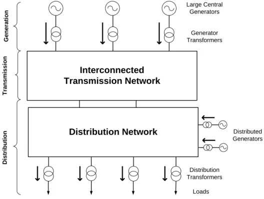
The organization of electrical power systems over the last 50 to 60 years has followed a traditional hierarchical structure as shown in Figure 1-1. This structure has three different levels: generation, transmission and distribution.
Figure 2-1 – Organization of Conventional Electrical Power Systems (adapted from [7])
The generation level is characterized by large generators that rely mostly on three types of technologies: hydro units (either run-of-the-river or dams), thermal units based on fossil-fuels (burning fuels such as coal, oil or natural gas) or nuclear units. These large central generators feed electrical power through generator transformers to an HV transmission system. The transmission system, which can cover large distances at HV levels, is then used to transport the
Interconnected
Transmission Network
Large Central Generators Loads Generator Transformers Distribution Transformers Distribution Network G e n e ra ti o n T ra n s m is s io n D is tr ib u ti o nelectrical power that is finally delivered to the final customers through distribution transformers [7], [8].
Regarding the generation level, the use of large generators holds some advantages, resulting from economy of scale effects [9]:
Size improves thermal efficiency – it is well known that the efficiency of a larger unit may be better since, for instance, heat losses related to unit size decreases in proportion, thus improving the potential efficiency of the unit.
Possibility of doubling generation capacity for a lower cost – by assembling multiple units of the same type at one same site it may be cheaper to double the capacity as some facility costs (such as insulation, conversion, protection and control costs) can be shared, thus lowering both investment and maintenance costs.
Of course, the fuel cost (if applicable) and its availability also have great influence on both the capacity and type of technology chosen for generation. Coal, for instance, is still plentiful and cheap in several regions although serious pollution issues have to be taken into account. In this context, the main mission of conventional Transmission and Distribution (T&D) systems is [9]:
To cover the service territory, reaching power consumers; To have sufficient capacity to cover consumer peak demand; To provide reliable delivery to the electric power consumers; To ensure stable voltage quality to the electric power consumers.
In short, this traditional electric power system is structured in a strict hierarchical radial manner, comprising several voltage levels, that can pick bulk power at a few large central generation plants and deliver it in smaller amounts to a large set of customers distributed across a wide territory. As a result, the conventional power system is characterized by unidirectional flows of energy from the generation to the distribution levels using an interconnected transmission network, resulting in rather straightforward planning and operation approaches.
Furthermore, traditional utilities usually operate in well-defined geographical territories within local market monopolies under the strict supervision of regulatory bodies. These utilities own the generation, transmission, and distribution facilities within their assigned service territories and finance the construction of the required facilities subject to the approval by the relevant regulatory bodies [8].
In recent times, and particularly since the last years of the 20th Century, a growing interest in the development of DG – as opposed to the traditional large central generation – has occurred. Firstly, it should be stressed that DG is not a purely new concept. In fact, in the early days of electricity generation, generation plants would supply power only for customers that were located in close proximity to them [10]. In this case, the networks were Direct Current (DC) based and would cover only small distances to feed the demand since the supply voltage was still limited (Alternate Current – AC – was later favoured to cover large distances without
consumption, local storage (typically in the form of batteries) was used in addition to small-scale generation. As will be seen throughout this thesis, both these concepts are now coming back to the scene in a wholly new context [10].
The advent of DG faces considerable challenges and requires significant changes in the way the electrical power system is regarded at many levels, from planning to operation of the electrical power system, since the networks are changing from mere passive networks to fully active networks. The new organization of the electrical power system is shown in Figure 2-2.
Figure 2-2 – Organization of Electrical Power Systems with Distributed Generation 2.1.2 The Distributed Generation Concept
Although there is still no consistent and unified definition, DG (also referred to in the scientific literature as Dispersed Generation, Decentralized Generation or Embedded Generation) can be loosely defined as small-scale generation connected to the distribution network. Actually, several definitions for DG can be found in the available literature.
Between 1997 and 1999, DG was investigated by two working groups of CIGRE8 and CIRED9: the CIGRE working group on “Impact of increasing contribution of dispersed generation on the power system” (WG 37-23) and CIRED working group on “Dispersed Generation” (WG 04). These two reports are largely complementary and provide a comprehensive review on the
8
CIGRE (International Council on Large Electric Systems) is one of the leading worldwide organizations on electric power systems, covering their technical, economic, environmental, organizational and regulatory aspects.
For more information see http://www.cigre.org/
9 CIRED (International Conference on Electricity Distribution) is a leading forum where the international
electricity distribution community meets. This conference is presently organized by the Institution of Engineering and Technology (IET), formerly Institution of Electrical Engineers (IEE).
Large Central Generators Loads Generator Transformers Distribution Transformers G e n e ra ti o n T ra n s m is s io n D is tr ib u ti o
n
Distribution Network
DistributedGenerators
Interconnected
Transmission Network
main issues associated with DG. The CIRED working group created and issued a questionnaire composed of 22 questions in order to try to identify the current state of DG in the various CIRED countries and to establish how DG was managed with reference to the distribution system [11]. Some 16 countries provided replies that served as a basis for forming a general view of the state of DG. Interestingly enough, even on the question of definition there was no clear consensus as to what constituted DG. Some countries used a definition based on the voltage level while others considered that DG was connected to circuits from which consumer loads were supplied directly. Additionally, certain definitions relied on the type of prime mover or were based on the generation not being dispatched whereas some other were based on a maximum power rating.
Jenkins et al. [7] agreed on some common attributes for DG, following the work of both the CIGRE and CIRED working groups: it is not centrally planned or dispatched, it is normally smaller than 50-100 MW and is usually connected to the distribution system (considering that distribution systems are networks to which customers are connected directly and which are typically of voltages from 230 V / 400 V up to 145 kV). They also considered that this broad description is to be preferred to any particular limits based either on plant size, voltage level or prime mover type.
In [9], Willis et al. define DG as small generators, typically ranging from 15 kW to 10 MW, that are scattered throughout a power system to provide electric power needed by electrical consumers. The term includes all use of small electric power generators, whether located on the utility system, at the site of a utility customer or at an isolated site not connected to the power grid. It is also mentioned that DG uses traditional power generation sources such as diesel, combustion turbine, combined cycle turbine, etc. but also includes fuel cells and renewable power generation technologies such as wind or solar because their small size makes them very convenient to connect to lower voltage parts of the electric grid. Here again dispersed generation has a different definition as it is considered as a subset of DG, referring to generation that is located at customer facilities or outside the utility system, usually with sizes in the range of 10 to 250 kW.
According to Ackermann et al. [12], DG is an electric power source connected directly to the distribution network or on the customer side of the meter. On one hand, this definition does not define the rating of the generation source; however some categories are suggested: micro DG for sources smaller than 5 kW, small DG for sources ranging from 5 kW to 5 MW, medium DG for sources ranging from 5 MW to 50 MW and large DG for sources ranging from 50 MW to 300 MW. On the other hand, this definition also does not address the technology used, although the following categories are proposed: renewable, modular and Combined Heat and Power (CHP), i.e. simultaneous generation of both electricity and useful heat. Finally, no reference is made to either the penetration level or the ownership of the DG units.
Borbely et al. [13] consider that the term DG refers to power generation technologies below 10 MW electrical output that can be sited at or near the load they serve. For this reason, they consider that not all small-scale technologies should be included in this category. For instance, hydro and wind generators are said to be too “fuel-dependent” (i.e. their location is dictated
by the availability of moving water or wind) to be considered truly load-sited or distributed generation.
The International Energy Agency10 [14] states that DG is a generating plant serving a customer on-site or providing support to a distribution network, connected to the grid at distribution level. In terms of technologies used, it generally includes engines, small (and micro) turbines, fuel cells and photovoltaic (PV) systems, and normally excludes wind power since it is considered that this type of energy is mostly produced on wind farms rather than for on-site power requirements. In this case, rather than being a synonym of DG, dispersed generation is regarded as DG plus wind power and other generation, either connected to a distribution network or completely independent of the grid.
For Dondi et al. [15], DG is a small source of electric power generation or storage (typically ranging from less than a kW to tens of MW) that is not a part of a large central power source and is located close to the load. DG includes biomass based generators, combustion turbines, concentrating solar power and PV systems, fuel cells, wind turbines, microturbines, engine/generator sets, small hydro plants as well as storage technologies. These can either be grid connected or operate independently of the grid. Those connected to the grid are typically interfaced at the distribution system, and thus dispersed across the utility’s electric network rather than concentrated in a single location.
In conclusion, and even though there are some significant differences between all these DG definitions, some common grounds can be found: it is usually connected to the distribution system and includes generators with relatively low capacity (at least when compared to large central generators). As shown above, no consensus is reached regarding such issues as DG technologies and applications, location or power capacity rating.
2.1.2.1 Distributed Energy Resources
Nowadays, DG is considered within the wider context of Distributed Energy Resources (DER), which form the core of the future power system. According to Lopes et al. [5], DER include not only DG but also distributed energy storage devices as well as responsive loads while other authors do not include storage within the DER concept [12], [14]. Throughout this thesis, the term DER will follow the definition proposed by Lopes et al. [5].
Considering the new paradigm in electrical power systems, energy storage can be an important supplement to DG for three main reasons [9]:
It can be used for stabilization purposes, allowing DG to run at a constant, stable output level;
It can provide energy to ride through periods when DG is not available (for instance, considering solar power at night-time);
It can allow a non-dispatchable DG unit to operate as a dispatchable unit by enabling its output to differ from the power being supplied to the grid.
10 The International Energy Agency (IEA) is an intergovernmental organization which acts as energy
policy advisor to 28 member countries (including Portugal) in their effort to ensure reliable, affordable and clean energy for their citizens.
In addition, important resources can also be found in the demand side. It is considered that these resources include load management systems that are able to shift electricity use from peak periods to off-peak periods and ensure energy efficiency options (e.g. reduce peak electricity demand, increase building efficiency or reduce overall electricity demand). Consequently, DER are not only based on local generation on the customer’s side of the meter but also on means to reduce peak or average customer demand, which will largely influence the electricity supply from the distribution network [12].
2.1.3 Main Distributed Generation and Storage Technologies
There is currently a wide variety of technologies that are usually associated to DG. These technologies may vary according to many parameters such as power rating, application type, electric conversion efficiency, type of fuel, investment and operation costs, GHG emissions,
etc. [10].
Several approaches to sort out the many different generating technologies can be found in the available scientific literature. According to Puttgen et al. [8], these technologies may be sorted into two separate categories: renewable and non-renewable. In turn, Ackermann et al. [12], although stating that the type of technology used for DG is not relevant for their proposed DG definition, suggest three alternative categories: renewable DG, modular DG and CHP. Finally, in [16], some other categories are proposed such as the classification in traditional generators (combustion engines) and non-traditional generators (remaining technologies).
Nevertheless, one issue that will significantly influence the impact of DG in the distribution system, particularly considering large-scale integration scenarios for DG, is the degree of controllability of the technology employed. Consequently, DG technologies can be divided into three categories, according to their degree of controllability:
Controllable;
Partially controllable; Non-controllable.
Table 2-1 presents a non-exhaustive list of the most common DG technologies, showing the typical range of capabilities and degree of controllability [8], [10], [12], [17].
Table 2-1 – Main Distribution Generation Technologies
Technology Typical Capability Ranges Controllability Solar PV A few W to a few MW Non-controllable
Wind A few hundred W to a few MW Non-controllable/ Partially controllable*
Microturbines A few tens of kW to a few MW Controllable
Fuel Cells A few tens of kW to a few tens of MW Controllable
Internal Combustion Engine A few kW to a tens of MW Controllable
Combined Cycle Gas Turbines A few tens of MW to several hundred
MW Controllable
Hydro A few kW to hundreds of MW Non-controllable Partially controllable**
* Depending on the type of technology used (conventional asynchronous generator, doubly-fed induction generator, synchronous generator with gearbox…)
Some of these technologies, as well as storage solutions, are briefly described in the following sections.
2.1.3.1 Photovoltaic Panels
PV generation (i.e. direct conversion of sunlight to electrical energy) is a relatively well established technology for several applications such as providing power for satellite equipments or for sites remote from the distribution grid [7], [17]. Although there is a number of large MW scale projects already deployed11, the main interest is now focusing on the application of small modules to roof tops and buildings in general.
The basic unit of PV is a cell usually made of doped silicon crystal. Cells are connected to form a module or panel and modules are connected to form an array in order to achieve the desired power capacity. Typical efficiency values are in the range of 15-20%,depending on the particular PV technology used [9].
Generally, PV panels have two main applications: grid-connected systems (with an inverter to serve AC loads) and stand-alone systems (supplying DC power directly to a DC load or used in combination with some form of storage such as “deep cycle” batteries). The use of the power electronic interface for grid-connected applications allows a better control of the output power. Frequently, PV panels use a Maximum Power Point Tracker (MPPT) in order to operate at the maximum power point, i.e. the operating condition where the most energy is captured [18].
The main advantages of this type of technology are its modularity, with a linear cost vs. capacity relationship that makes it ideal for small applications, and the fact that it is environmentally benign with no noise, pollution or vibration (in spite of adverse issues such as land use).
PV generation is foreseen to have a large importance in the future since technological maturity and market demand will lower considerably the installation costs so that it will become one of the most used technologies in the future generation mix. In fact, considering the connection of small PV installations directly to customers’ circuits (interfacing with the LV distribution network), a potential large number of residences and commercial buildings may be equipped with PV generators in a near future [7].
2.1.3.2 Wind Generators
Wind energy is a form of energy used for decades and thus has more cumulative experience than most other energy sources. In fact, wind generation is possibly the renewable source with the most mature technology. Wind generation uses wind turbines to exploit the wind’s kinetic energy in order to drive electric power generators. Basically, the wind rotates the blades which in turn rotate their attached shaft. This shaft moves a generator that produces electricity.
11
![Figure 2-3 – Relative Levels of System Capacity under Centralized and Distributed Control Strategies (adapted from [27])](https://thumb-eu.123doks.com/thumbv2/123dok_br/15485850.1039718/47.892.190.756.183.516/figure-relative-levels-capacity-centralized-distributed-control-strategies.webp)
![Figure 3-4 – Data Exchange between the CAMC, the MGCC, MV Loads and DG Units (adapted from [78])](https://thumb-eu.123doks.com/thumbv2/123dok_br/15485850.1039718/85.892.158.779.110.454/figure-data-exchange-camc-mgcc-loads-units-adapted.webp)
![Figure 5-1 – VPP Concept from a Technical Perspective and from a Market Perspective (adapted from [91])](https://thumb-eu.123doks.com/thumbv2/123dok_br/15485850.1039718/127.892.260.685.110.867/figure-vpp-concept-technical-perspective-market-perspective-adapted.webp)