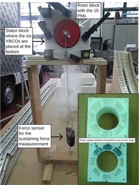
Experimental set-up and efficiency evaluation of zero-field-cooled (ZFC) YBCO magnetic bearings
5
0
0
Texto
Imagem


Documentos relacionados