Analysis of the Effect of Electric and Magnetic Loadings on the
Design Parameters of an Induction Motor and Its Performance
Using Matlab/Simulink
Folorunso Oladipo*, Olowu Temitayo O**, Orizu Eziafa F***.
*(Department of Electrical/Electronic & Computer Engineering, Afe Babalola University, Ado Ekiti, Nigeria) **(Department of Electronic & Electrical Engineering, Obafemi Awolowo University, Ile-Ife, Nigeria) ***( National Engineering Design Development Institute, Nnewi, Nigeria)
Abstract
This paper looks at the effect of magnetic loading and electric loading on the design parameters of an induction motor and its performance. The study involves the use of MATLAB to simulate 50kW, 3-phase, 415V, 50Hz, 6 poles induction machine. Based on the variation of the magnetic and electric loading of the machine, the various design values of the rotor and stator of the machine are specified. The performance index which includes stator loss, rotor loss, cost, power factor, efficiency, and torque are also specified for squirrel cage induction motor (SCIM)
Keyword
: MATLAB, stator, rotor, magnetic loading, electric loading, SCIM.I.
INTRODUCTION
Generally, all rotating electrical machines work by the interaction of the magnetic field set up in stator and rotor windings of the machines to convert mechanical energy into electrical energy and vice versa. These machines include induction motors, direct current motors, synchronous motors and other rotating electrical machines. The commonly used of all these machines is the induction motor; reason for this is its ruggedness, and lower cost [1]. One major feature that differentiates induction motor from synchronous motor is the slip between the rotational speed of the stator field and somewhat slower speed of the rotorfield. The synchronous machines run at the speed that equals the synchronous speed of the stator field. [2]
The performance analysis of a 50KW, 3-phase 6-poles induction motor is the central focus of this paper. This is based on effect of the electromagnetic loading of the machine.
This gives an insight to how this motor can be adapted to various drives purposes.
II.
ELECTRIC AND MAGNETIC
LOADING IN INDUCTION
MOTORS:
There are two parameters that guide the design of electric motors which are, the specific electric loading, and the specific magnetic loading. These parameters have a direct bearing on the output of the motor.
The specific electric loading (B) is the average radial flux density over the cylindrical surface of the rotor, while the specific electric loading (q) is the
axial current per meter of circumference of the rotor [3].
Advantages of higher value of B include lower size of the machine, decrease in cost of the machine, increase in machine overload capacity [4].
Advantages of higher value of q include reduced size, reduced cost of machine.
Disadvantages of higher value of q include, higher amount of copper, more copper losses, increased temperature rise, lower overload capacity [4]
III.
METHODOLOGY
3.1 DEVELOPMENT OF SIMULATION GUI
USING MATLAB
MATLAB is built around a programming
language, and as such it’s really designed with tool-building in mind. Guide extends MATLAB’s support for rapid coding into the realm of building GUIs. Guide is a set of MATLAB tools designed to make building GUIs easier and faster. Just as writing math in MATLAB is much like writing it on paper, building a GUI with Guide is much like drawing one on paper. As a result, you can lay out a complex graphical tool in minutes. Once your buttons and plots are in place, the Guide Callback Editor lets you set up the MATLAB code that gets executed when a particular button is pressed [5]. The full meaning of GUI is Graphics User Interface.
3.2. MODELING EQUATIONS
In design of electrical machines, the requirement is to design the stator core, tooth and windings. Similarly, rotor core, tooth and rotor windings.
3.2.1 POWER OUTPUT EQUATION OF ELECTRICAL MACHINES
This gives a relationship between length, diameter (physical dimension) and electrical rating of the machine. For a single phase machine, power is expressed in the form
= ∅ … … … ….1
Considering efficiency of device, then output power is given in equation 2:
= ∅ ∗ � … … …2
For multi-phase machine,
= � ∗ � ∗10−3
where m = number of phase v = input voltage (phase) i = input phase current cos∅ = input power factor
� = efficiency of motor
By considering the RMS of voltage ( = 4.44��� , substituting the magnetic loading (�= � � ) and the electric loading ( � = 2 � ), the power output is expressed as given in equation 3.
= 2� . .…. .3
is the output coefficient of the machine which is given as 1.11�2 ∗10−3; n is speed in rps.
From equation 3, conclusion it can be concluded that output power of a machine is a function of its main dimension, specific magnetic loading and electric loading.
3.2.2 STATOR DESIGN EQUATIONS
The following equations are few of part equations considered:
=
∗ … …4
,�=
0.018225∗ 2 .….5
where P is the number of poles.
, = ∗
�
3
… …6
� =� … … ….7 �=
4.44∗ � ∗ � ∗ … …8
= 2 � … …. .9
, =0.2 + �
1000 … …. .10 , = 3 … …. .11
, =
� … …12
where Js is the stator current density
, = � … … …13
, = � … …. .14
,
= 2�+ 2.3 �
+ 0.24… … ….15 ,
= 0.021∗10
−6∗ ∗ �
… ….16 , = 32 …17
, ≅
0.55 ….18
, = − + 2
2 ….19
3.2.3 ROTOR DESIGN EQUATIONS
The various rotor parts considered in this study include the following.
, ≅1.5 + −1 + ( −2 + − −1 + ( − −2))/4 ..20
=2 � 0.55… ….21 , = −2 lg … …. .22
, = �
∗ ….23
, =� …24
, = 0.85 …. .25 ,
= ∗ ∗ ∗ …26
, =�+ 0.046 …. .27 ,
=
� … ….28 � ;
, = 0.021∗10−6∗ …. .29
, = 2 ∗ …30
, = ∗ � ….31
, ≅ � −0.48 …32
, =
� …. .33 ,
= 0.021∗10−6∗ …. .34
IV.
SIMULATION INPUT AND OUTPUT
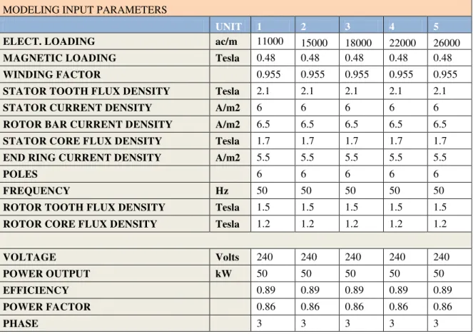
Table 1: Variation of Electrical Loading with all other parameter remain constant MODELING INPUT PARAMETERS
UNIT 1 2 3 4 5
ELECT. LOADING ac/m 11000 15000 18000 22000 26000
MAGNETIC LOADING Tesla 0.48 0.48 0.48 0.48 0.48
WINDING FACTOR 0.955 0.955 0.955 0.955 0.955
STATOR TOOTH FLUX DENSITY Tesla 2.1 2.1 2.1 2.1 2.1
STATOR CURRENT DENSITY A/m2 6 6 6 6 6
ROTOR BAR CURRENT DENSITY A/m2 6.5 6.5 6.5 6.5 6.5
STATOR CORE FLUX DENSITY Tesla 1.7 1.7 1.7 1.7 1.7
END RING CURRENT DENSITY A/m2 5.5 5.5 5.5 5.5 5.5
POLES 6 6 6 6 6
FREQUENCY Hz 50 50 50 50 50
ROTOR TOOTH FLUX DENSITY Tesla 1.5 1.5 1.5 1.5 1.5
ROTOR CORE FLUX DENSITY Tesla 1.2 1.2 1.2 1.2 1.2
VOLTAGE Volts 240 240 240 240 240
POWER OUTPUT kW 50 50 50 50 50
EFFICIENCY 0.89 0.89 0.89 0.89 0.89
POWER FACTOR 0.86 0.86 0.86 0.86 0.86
PHASE 3 3 3 3 3
Table 2: Variation of Magnetic Loading with all other parameter remain constant MODELING INPUT PARAMETERS
UNIT 1 2 3 4 5
ELECT. LOADING ac/m 11000 11000 11000 11000 11000
MAGNETIC LOADING Tesla 0.48 0.5 0.62 0.72 0.82
WINDING FACTOR 0.955 0.955 0.955 0.955 0.955
STATOR TOOTH FLUX DENSITY Tesla 2.1 2.1 2.1 2.1 2.1
STATOR CURRENT DENSITY A/m2 6 6 6 6 6
ROTOR BAR CURRENT DENSITY A/m2 6.5 6.5 6.5 6.5 6.5
STATOR CORE FLUX DENSITY Tesla 1.7 1.7 1.7 1.7 1.7
END RING CURRENT DENSITY A/m2 5.5 5.5 5.5 5.5 5.5
POLES 6 6 6 6 6
FREQUENCY Hz 50 50 50 50 50
ROTOR TOOTH FLUX DENSITY Tesla 1.5 1.5 1.5 1.5 1.5
ROTOR CORE FLUX DENSITY Tesla 1.2 1.2 1.2 1.2 1.2
VOLTAGE Volts 240 240 240 240 240
POWER OUTPUT kW 50 50 50 50 50
EFFICIENCY 0.89 0.89 0.89 0.89 0.89
POWER FACTOR 0.86 0.86 0.86 0.86 0.86
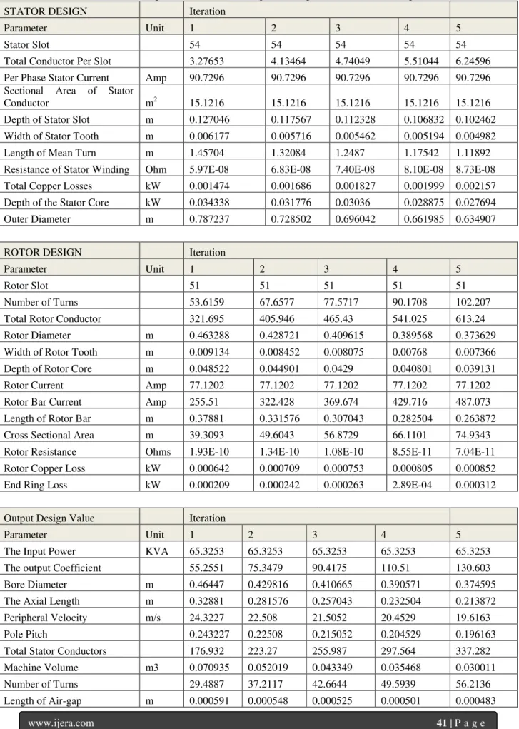
Table 3: Output of the Machine Design with respect to Electrical loading
STATOR DESIGN Iteration
Parameter Unit 1 2 3 4 5
Stator Slot 54 54 54 54 54
Total Conductor Per Slot 3.27653 4.13464 4.74049 5.51044 6.24596 Per Phase Stator Current Amp 90.7296 90.7296 90.7296 90.7296 90.7296 Sectional Area of Stator
Conductor m2 15.1216 15.1216 15.1216 15.1216 15.1216 Depth of Stator Slot m 0.127046 0.117567 0.112328 0.106832 0.102462 Width of Stator Tooth m 0.006177 0.005716 0.005462 0.005194 0.004982 Length of Mean Turn m 1.45704 1.32084 1.2487 1.17542 1.11892 Resistance of Stator Winding Ohm 5.97E-08 6.83E-08 7.40E-08 8.10E-08 8.73E-08 Total Copper Losses kW 0.001474 0.001686 0.001827 0.001999 0.002157 Depth of the Stator Core kW 0.034338 0.031776 0.03036 0.028875 0.027694 Outer Diameter m 0.787237 0.728502 0.696042 0.661985 0.634907
ROTOR DESIGN Iteration
Parameter Unit 1 2 3 4 5
Rotor Slot 51 51 51 51 51
Number of Turns 53.6159 67.6577 77.5717 90.1708 102.207 Total Rotor Conductor 321.695 405.946 465.43 541.025 613.24 Rotor Diameter m 0.463288 0.428721 0.409615 0.389568 0.373629 Width of Rotor Tooth m 0.009134 0.008452 0.008075 0.00768 0.007366 Depth of Rotor Core m 0.048522 0.044901 0.0429 0.040801 0.039131 Rotor Current Amp 77.1202 77.1202 77.1202 77.1202 77.1202 Rotor Bar Current Amp 255.51 322.428 369.674 429.716 487.073 Length of Rotor Bar m 0.37881 0.331576 0.307043 0.282504 0.263872 Cross Sectional Area m 39.3093 49.6043 56.8729 66.1101 74.9343 Rotor Resistance Ohms 1.93E-10 1.34E-10 1.08E-10 8.55E-11 7.04E-11 Rotor Copper Loss kW 0.000642 0.000709 0.000753 0.000805 0.000852 End Ring Loss kW 0.000209 0.000242 0.000263 2.89E-04 0.000312
Output Design Value Iteration
Parameter Unit 1 2 3 4 5
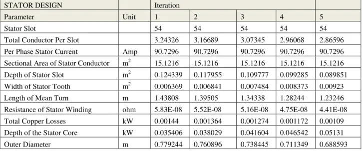
Table 4: Output the Machine Design with Magnetic Loading
STATOR DESIGN Iteration
Parameter Unit 1 2 3 4 5
Stator Slot 54 54 54 54 54
Total Conductor Per Slot 3.24326 3.16689 3.07345 2.96068 2.86596 Per Phase Stator Current Amp 90.7296 90.7296 90.7296 90.7296 90.7296 Sectional Area of Stator Conductor m2 15.1216 15.1216 15.1216 15.1216 15.1216 Depth of Stator Slot m2 0.124339 0.117955 0.109777 0.099285 0.089851 Width of Stator Tooth m2 0.006369 0.006841 0.007484 0.008373 0.00923 Length of Mean Turn m 1.43808 1.39505 1.34338 1.28244 1.23246 Resistance of Stator Winding ohm 5.83E-08 5.52E-08 5.16E-08 4.75E-08 4.41E-08 Total Copper Losses kW 0.00144 0.001364 0.001274 0.001172 0.00109 Depth of the Stator Core kW 0.035406 0.038029 0.041604 0.046542 0.05131 Outer Diameter m 0.779244 0.760896 0.738445 0.711349 0.688593
ROTOR DESIGN Iteration
Parameter Unit 1 2 3 4 5
Rotor Slot 51 51 51 51 51
Number of Turns 53.0715 51.8219 50.2928 48.4474 46.8976 Total Rotor Conductor 318.429 310.931 301.757 290.684 281.385 Rotor Diameter m 0.458584 0.447786 0.434572 0.418625 0.40523 Width of Rotor Tooth m 0.009417 0.010115 0.011066 0.01238 0.013648 Depth of Rotor Core m 0.05003 0.053737 0.058789 0.065766 0.072504 Rotor Current Amp 77.1202 77.1202 77.1202 77.1202 77.1202 Rotor Bar Current Amp 252.916 246.961 239.674 230.88 223.494 Length of Rotor Bar m 0.372167 0.357174 0.339314 0.318472 0.30157 Cross Sectional Area m 38.9102 37.994 36.8729 35.52 34.3837 Rotor Resistance Ohms 1.91E-10 1.88E-10 1.84E-10 1.79E-10 1.75E-10 Rotor Copper Loss kW 0.000624 0.000585 0.000539 0.000487 0.000447 End Ring Loss kW 0.000204 0.000194 0.000182 1.69E-04 0.000157
Output Design Value Iteration
Parameter Unit 1 2 3 4 5
V.
CONCLUSION
The choice of magnetic and electrical loading in the design of domestic and industrial machine is very important as these defined the performance of the machine. From the observation of this study, it can be concluded that increase magnetic loading is a better choice for loss reduction, decrease in the outer diameter, decrease in the rotor number of turns, decrease in bore diameter, decrease in rotor diameter, decrease in length of air-gap, etc. The economy benefit of this is reduction in the cost of the machine.
REFERENCE
[1] Austin hughes, Bill Drury,“Electric motor and drives; fundamentals, types and applications” Published by Elsevier Ltd.Third edition 2006.
[2] Edward J. Thornton and J. Kirk Armintor “
the fundamental of AC electric induction motor design and application; proceedings of the twentieth international pump users
symppsium, 2003
[3] K. L . SHI, T . F. CHAN, Y. K. WONG and
S. L . HO, “Modelling And Simulation Of The Three-Phase Induction Motor Using Simulink, Int. J. Elect. Enging. Educ., Vol. 36, pp. 163–172. Manchester U.P., 1999. Printed in Great Britain
[3] A.K Sawhney, “A course in electrical machine design” 5th edition.