BJRS
RADIATION SCIENCES
07-02A (2019) 01-20ISSN: 2319-0612
Experimental hypofractionated IMRT breast dosimetry in a
thorax phantom
Pimenta
aE. B., Campos
aT. P. R., Nogueira
bL. B., Lima
cA. C. S.
aUniversidade Federal de Minas Gerais /Departamento de Engenharia Nuclear, 31270-901, b Universidade Federal de Minas Gerais / Departamento de Anatomia e Imagem, 30130-100,
Belo Horizonte, Minas Gerais, Brasil
c Centro de Tratamento em Radioterapia, 32651-760,
Betim, Minas Gerais, Brasil [email protected]
ABSTRACT
The present research proposal aimed to measure absorbed dose in a thorax phantom with synthetic breasts pro-vided by an Intensity-Modulate Radiation Therapy (IMRT) protocol in an arbitrary RT center. As methods, a thorax simulator was prepared by the Ionizing Radiation Research Group (NRI) and radiochromic films were used for dose measurements. Hypofractionated regime was considered with a dose fraction of 2,7Gy in 16 frac-tions at the prescribed dose of 43.2 Gy at 95% of PTV. The dose comparison from the treatment planning system (TPS), Xio (Elekta) and from the experimental data was performed. The internal two-dimensional dose maps in the breast, at the skin on the left and contra-lateral breasts, heart and lungs. The measurements showed that the internal mean doses taken at the synthetic breast presented mean doseabove the prescribed dose. Moreover, in
general, doses to organs at risk (OARs) were within the Memorial Sloan Kettering Cancer Center (MSKCC) criteria. The non-full reproduction of the build-up region in the films had occurred due to the assymetrical posi-tioning of the films in the inner breast, in the addition to their non-constant distance from the skin. Hot regions were present, may be due to the beam angulation chosen and the increase of MUs in the IMRT plane. As conclu-sions, the films can supply details and information that TPS does not provide. Assertiveness in clinical IMRT
protocols can improve the prognosis and effectiveness of breast cancer treatment bringing possible clinical bene-fits.
1. INTRODUCTION
Radiotherapy planning is an essential part of the RT process, although the treatment planning must be performed accurately to ensure the RT efficiency and patient safety. It is necessary that the dosimetrists, the radiotherapist physician and the physicists have the accuracy of the dosimetric protocol preserved. Therefore, quality assurance (QA) in the RT service is necessary and fundamen-tal. The dose calculations provided by the treatment planning system (TPS) and the ability of per-forming the plan must always be verified. It is a RT requirement that the patient receives the entire prescribed dose in the target volume (PTV), holding the tolerable doses in the adjacent organs at risk (OARs). The International Commission of Radiation Unit and Measurements (ICRU) defines an OAR to be an uninvolved RT organ that, if receiving too much radiation dose, could be damaged and would compromise the success of the course of radiation therapy [13].
In a 3D conformational RT (3DCRT) modality, the verification of the dose in the central axis is usually required; besides, previous acceptable conditions of beam symmetry and beam flatness [1]. QA is more laborious in the Intensity Modulated Radiation Therapy (IMRT) modality. IMRT ap-plies a modulated beam and requires accurate dose verification. Therefore, such modality requires a more complex analysis as gamma analysis. However, there are no robust protocols that can estab-lish QA to the internal dose in patients.
Radiochromic films can be used to RT dosimetry internally in phantom-based studies, at the dose range of 1 cGy to 40 Gy [10,11]. Several studies have shown that the Gafchromic EBT2 (GAF-EBT2), produced by International Specialty Product (ISP), has advantage properties such as high spatial resolution, minimum angular dependence, low spectral sensitivity and tissue equiva-lence (42.3% C, 39.7% H , 16.2% O, 1.1% N, 0.3% Li and 0.3% Cl), besides EBT2 provides a two-dimensional dose distribution [2-8]. The effective atomic number of the EBT2 Lot # F020609 is 6.84 [9]. In addition, GAF-EBT2 is a low-cost dosimetric tool in comparison to semi-conductor or gas detectors for dose measurements. According to Kairn et al. [5], images from films provide suf-ficient information to verify the treatment´s dosimetry. One can check the dose delivered and guar-antee an acceptable level of accuracy, as well as provide additional information on low-level dose regions non anticipated by TPS.
The research group NRI- “Nucleo de Radiação Ionizante” from UFMG elaborated a thorax phantom and hold the ability of comparing the spatial dose distribution, measured by radiochromic films, with the internal doses prescribed in the TPS. The thorax phantom has distinct internal or-gans, bone structure, skin, both breasts with adipose and glandular tissue, well defined. Such tools are indispensable for experimental evaluation of the internal spatial dose distribution.
The present paper has the goal of evaluated the internal doses at a synthetic left-breast of a thor-ax phantom, following IMRT protocol and make the comparison to its respective TPS. Such infor-mation may contribute to the quality control of internal dose in patients with breast cancer.
2. MATERIALS AND METHODS
2.1 Calibration protocol
Dosimetry was performed following the TRS-398 protocol of the International Atomic Energy Agency (IAEA). The radiochromic films used for the experimental dosimetry were the Gafchromic EBT2 films (GAF-EBT2). The films were positioned perpendicular to the central axis of the beam with the distance of the source to the surface (SSD) of 100 cm and at 5 cm depth in a phantom model RW3 of the manufacturer PTW. GAF-EBT2-type films were exposed to 6MV photon beam in a 10 cm x 10 cm window, from the Elekta Precise Linear Accelerator (Linac) at the “Centro de Tratamento de Radioterapia” – Betim city. The doses delivered to each GAF-EBT2 film ranged from 58 to 462 Monitor Units (MU) corresponding to 50.2 to 400.1 cGy, respectively.
2.2 Phantom, tomography and Treatment Planning
The simulator object was a female thorax phantom developed by the NRI research group. The phantom is an anthropomorphic and anthropometric synthetic object made of equivalent elastomer-based tissue. The skin was prepared by animal collagen and silicone. The compounds used in the adipose tissue were paraffin, vegetable wax and mineral oil. The rib was made of bone powder [12 - 16].
The CT images of the thorax phantom were acquired in Siemens SOMATOM EMOTION 16-channels with a thickness of 1.5 mm. The position of the phantom on the CT scanner was supine placed on a radiolucent polyurethane support. Fiducial marks were fixed on the skin for the repro-ducibility of the experiment and of the isocenter positioning, respectively. The adopted planning protocol was the inverse IMRT step-and-shoot technique performed in XiO 5.10 Elekta planning system (TPS), based on the superposition algorithm. At the TPS, the following structures were de-lineated in all CT slices: clinical target volume (CTV), planning target volume (PTV), ipsilateral, contralateral lungs, contralateral breast and heart, taken as OARs.
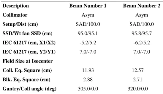
The treatment plan was optimized using a hypofractionation regimen with a prescribing dose of 43.20 Gy for 95% isodose on the total left breast (PTV) in 16 fractions of 2.70 Gy with four 6MV coplanar fields – two external and two internal. The four 6MV coplanar fields EXT1, INT1, EXT2 and INT2 were presented in Figure 4. The CTV margin was expanded with 1-cm of PTV. A dis-tance of 3-mm into the skin surface was established at the CTV. Taking into account the anatomy of the phantom, the most suitable field number was four. Table 1 and 2 shows the radiotherapy plan-ning protocol for NRI Thorax Phantom. Different combinations of the gantry and the collimator angles were used for defining each field, holding asymmetric collimators to obtain dose homogenei-ty in this region. All fields were set up at the 100-cm source to axis distance (SAD).
Table 1: Radiotherapy Planning Protocol for NRI Thorax Phantom
Description Beam Number 1 Beam Number 2
Collimator Asym Asym
Setup/Dist (cm) SAD/100.0 SAD/100.0
SSD/Wt fan SSD (cm) 95.0/95.1 95.8/95.7
IEC 61217 (cm, X1/X2) -5.2/5.2 -6.2/5.2
IEC 61217 (cm, Y2/Y1) 7.0/-7.0 7.0/-7.0
Field Size at Isocenter
Coll. Eq. Square (cm) 11.93 12.57
Blk. Eq. Square (cm) 2.88 2.71
Couch (deg) 0.0 0.0
Weight (cGy)/No. fractions 1112.8/16 1196.5/16
Defined at Arb.point Arb.point
Depth; skin (cm) 4.9 4.3
Min or MU(open/wdg) 167.23 (MU) 181.77 (MU)
Integer MU(open/wdg) 167 182
Field ID INT1 INT2
Table 2: Radiotherapy Planning Protocol for Thorax Phantom (Continued)
Description Beam Number 3 Beam Number 4
Collimator Asym Asym Setup/Dist (cm) SAD/100.0 SAD/100.0 SSD/Wt fan SSD (cm) 91.6/91.7 92.8/92.7 IEC 61217 (cm, X1/X2) -5.2/5.2 -5.2/4.2 IEC 61217 (cm, Y2/Y1) 7.7/-7.6 7.7/-7.6
Field Size at Isocenter
Coll. Eq. Square (cm) 12.38 11.65
Blk. Eq. Square (cm) 4.10 3.05
Gantry/Coll angle (deg) 125.0/0.0 115.0/0.0
Couch (deg) 0.0 0.0
Weight (cGy)/No. fractions 1188.2/16 998.2/16
Defined at Arb.point Arb.point
Depth; skin (cm) 8.3 7.3
Min or MU(open/wdg) 137.18 (MU) 133.36 (MU)
Integer MU(open/wdg) 137 133
Field ID
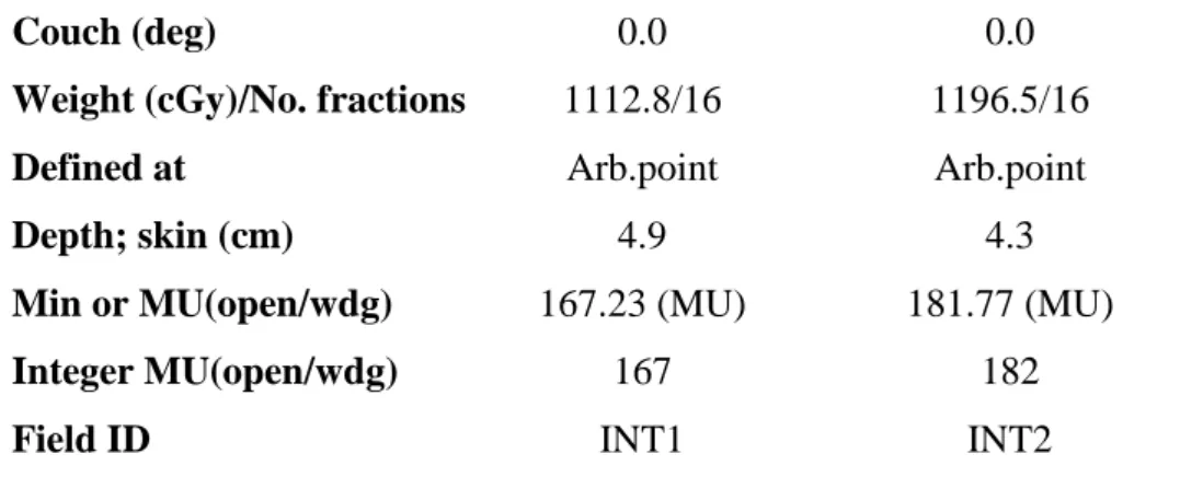
Radiochromic films were inserted in various regions of the phantom. These were applied to the skin and inside the breast. In the skin, films were placed in the ipsilateral breast and in the contrala-teral breast. On the skin of the ipsilacontrala-teral breast, 04 films of 3x2 cm2 were placed in each quadrant of the breast skin. This is shown in Figure 1, where BS1 and BS4 films were set at upper and lower medial quadrant, respectively. Similarly, BS2 and BS3 films were placed at upper and lower lateral quadrant, respectively. Moreover, in the same dimension, 01 film was positioned on the medial region. As shown in Figure 2, a scheme of 04 films M1, M2, M3 and M4 with the size and shape of the breast were set inside the ipsilateral breast along the axial axis and 01 film of 5x5 cm2 was placed into the breast bed. Furthermore, in the contralateral breast, 01 film of 3x2 cm2 was also po-sitioned in the breast bed at inferior medial quadrant. In addition, same size films were fixed in the heart at the myocardium surface and into each lung (medium position), bellow to the breasts.
Figure 1: Position of radiocromic films on the skin of the thorax phantom
2.3 Dosimetry
A radiopaque film (black), a virgin non-irradiated film and a set of irradiated films, in triplicate, were scanned five times on the HP Scanget G 4050 scanner. The matrices of the RGB values of the selected ROI in each film were obtainned through the ImageJ program. Only the matrices of the red component were used. Since the absorbance spectra of the active component of Gafchromic EBT2 have a peak at 636 nm, the films have their sensitivity maximized by measurements on red color channel [7]. Thus, the RGB value was converted to net optical density (netOD) following the rela-tion:
netOD = Log10 (
𝑅𝐺𝐵𝑏𝑒𝑓𝑜𝑟𝑒 − 𝑅𝐺𝐵𝑏𝑐𝑘𝑔
𝑅𝐺𝐵𝑎𝑓𝑡𝑒𝑟 − 𝑅𝐺𝐵𝑏𝑐𝑘𝑔) (1)
in which RGBbefore is the mean of the RGB components of the non-irradiated film, RGBafter is the average of the RGB components of the irradiated film, and RGBbckg is the average of the RGB components of the opaque film. According to Devic et al [20], the standard deviation of optical den-sity (σnetOD) is given by:
σnetOD = 1 𝐿𝑛(10)√ ( 𝜎𝑎𝑓𝑡𝑒𝑟 𝑅𝐺𝐵𝑎𝑓𝑡𝑒𝑟−𝑅𝐺𝐵𝑏𝑐𝑘𝑔) 2 + ( 𝜎𝑏𝑒𝑓𝑜𝑟𝑒 𝑅𝐺𝐵𝑏𝑒𝑓𝑜𝑟𝑒−𝑅𝐺𝐵𝑏𝑐𝑘𝑔) 2 + [ 𝑅𝐺𝐵𝑏𝑒𝑓𝑜𝑟𝑒−𝑅𝐺𝐵𝑎𝑓𝑡𝑒𝑟 (𝑅𝐺𝐵𝑏𝑒𝑓𝑜𝑟𝑒−𝑅𝐺𝐵𝑏𝑐𝑘𝑔)(𝑅𝐺𝐵𝑎𝑓𝑡𝑒𝑟−𝑅𝐺𝐵𝑏𝑐𝑘𝑔)] 2 (𝜎𝑏𝑐𝑘𝑔)2 (2)
in which σbefore is the standard deviation of the RGB components of the non-irradiated film, σafter is the standard deviation of the RGB components of the irradiated film and σbckg is the standard deviation of the RGB components of the opaque film. And finally, the uncertainty of the dose takes into account the uncertainties of netOD measurements and the uncertainties of calibration curve fitting, as follows:
σDose = √𝑛𝑒𝑡𝑂𝐷2𝜎𝐴2+𝑛𝑒𝑡𝑂𝐷4 𝜎𝐵2+(𝐴+2𝐵𝑛𝑒𝑡𝑂𝐷)2𝜎𝑛𝑒𝑡𝑂𝐷2
𝐷𝑓𝑖𝑡 . 100 (3)
in which A and B are estimated values for each parameter of the best fit which would make the curve closest to the data points; σA and σB are the parameter standard errors of A and B; Dfit is the mathematical function of the fitted dose value.
A relationship between the optical density and the dose percentage was obtained through a non-linear fit between the OD values obtained in the calibration and the percentage of the dose in depth, related to the maximum dose in the profile of dose in depth.
After irradiation in the NRI phantom, the sensitized radiochromic films were removed from the left breast phantom, their sealing was removed, and they were scanned in a transmission scanner model HP Scanget G 4050. The scanned images were decomposed into their RGB components through the ImageJ programe, and ASCII files were generated, representing the red component. The data were converted into the optical density applied to each pixel in the decomposed image, pre-serving the spatial dose distribution according to Eq.1. The standard deviation was calculated ac-cording to Eq.3. Based on the response curve of the optical density versus dose percent generates, the optical density values were converted to the dose. The values of the dose were transformed into surface graphs, representing the spatial distribution of the doses, namely dose maps.
2.4. Statistical analysis of experimental dosimetry
Absorbed doses in radiochromic films were compared with absorbed doses calculated by the TPS in the equivalent areas of the breast phantom. The mean dose and its deviation were evaluated for each dose maps. The total standard deviations of the doses were calculated with Eq.3
3. RESULTS AND DISCUSSION
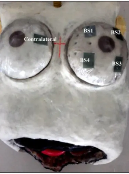
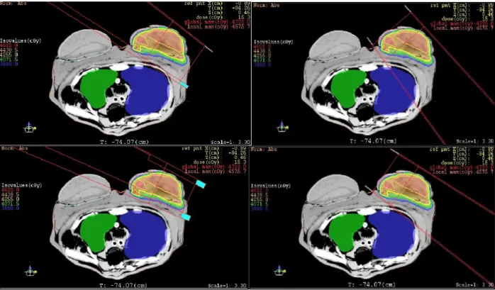
Figure 3 depicts the planning system superimposed to the NRI breast thorax phantom. The iso-dose regions were presented in Figure 3b at the PTV. Two regions of isovalues were depicted on the image.
Figure 3: a) Reconstruction of the 3D phantom planning and b) PTV and coverage of the organs at
risk in TPS Xio 5.10
The sensitometric curve obtained from the calibration films was adjusted with a second-order polynomial equation, shown in Figure 5.
0.00 0.05 0.10 0.15 0.20 0.25 -0.5 0.0 0.5 1.0 1.5 2.0 2.5 3.0 3.5 4.0 D o se (G y)
Net optical density
The most suitable adjustment of the sensitometric curve was a second-order polynomial equa-tion, as follows:
y = y0 + A.OD + B.OD2 (4)
in which y0 = (-0.01603 ± 0.03233) Gy, A = 5.97125 ± 0.54905 and B = 32.85115 ± 2.11665 and OD is the value of the optical density. The RGBbckg value presented 3.13 ± 0.48. The resulting optical density values were calculated by Eq.1. The optical density uncertainties obtained by Eq.2 were insignificant, much lower than 1%. The quadratic polynomial fit presented a satisfactory coef-ficient of determination of 0.99. The parameters of the quadratic polynomial function adjustment were used to convert the film reading to absorbed dose.
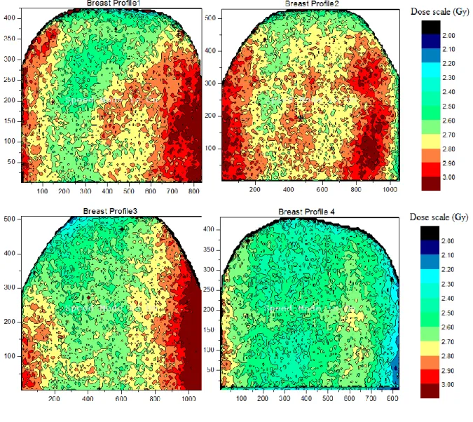
The dose matrices were presented in Figure 6, in the shape of dose bound surface planes. It was possible to identify the bidimensional distribution of internal dose in the breast, namely as two-dimensional dose maps.
Figure 6: Spatial dose maps generated in the internal left-breast for hypo fractioned 4-filed IMRT
protocol, XY-scales in mm.
Table 3: Mean dose and standard deviation at PTV and OARs.
Dose Maps (M) Mean Dose (Gy) Total Dose (Gy)
σDose(%) Constraints Mean Dose* (Gy)
PTV
M1 2.76 44.16 11.04 16 fractions, 2,7Gy
Prescribed dose of
M3 2.72 43.52 13.00 43.2 Gy at 95% of PTV M4 2.52 40.32 14.17 OAR Contralateral breast (skin) 0.45 7.20 11.14 5 Gy Contralateral breast (bed) 0.24 3.89 16.52 Ipsilateral lung 0.33 5.27 23.05 22 Gy Contralateral lung 0.20 3.25 17.16 - Heart (myocardium) 0.30 4.82 11.62 20 Gy
Abbreviations: PTV= planning target volume, OAR= organs at risk
* Constraints Dose from the literature summarized in Lee et al [17].
Table 3 presents the mean dose and standard deviation at PTV and on the OARs, including con-tralateral breast, ipsilateral lung, concon-tralateral lung and heart surface. The total dose was estiamated multiplying the mean dose at organ by the number of fractions specified by the hypofractionated treatament. The total dose in the organs at risk were also identified. In addition, table 4 presents the mean dose and standard deviation of the skin dose at the ipsiliateral breast, followed by the total dose after hypofractionated RT.
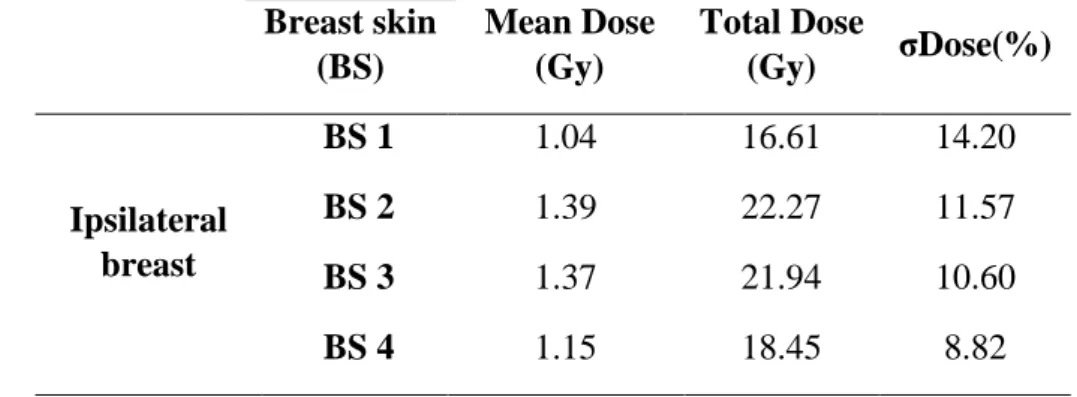
Table 4: Mean dose and standard deviation of the ipsilateral breast skin dose Breast skin (BS) Mean Dose (Gy) Total Dose (Gy) σDose(%) Ipsilateral breast BS 1 1.04 16.61 14.20 BS 2 1.39 22.27 11.57 BS 3 1.37 21.94 10.60 BS 4 1.15 18.45 8.82
Table 3 shows that the mean doses, taken at the internal breast in the PTV, presented usual val-ues above the prescribed dose, as expected. The concave shapes present on the dose distributions,
following the hot regions, are observed in Figure 6, following the breast surface contour. This large hot region with doses above 2.9 Gy on the sides of EBT2 films may have been assembled by the overlapping of two hot sub-regions. This phenomenon may have occurred due to the application of fields with close enter-angles. The defined angles were available in Tables 1 and 2.
The build-up region, in which the electron balance of the charged particles is reached, was not reproduced in the films because they were prepared with smaller dimension placed internally in the breast not covering the surface, whose borders were away from the surface (skin). The breast film representative of the M4 presented the lowest dose because it was near the surface of the skin, in the buildup region. It is likely that the variation between the mean doses in the breast may have oc-curred due to the asymmetrical positioning of the films in the internal breast, and their distance to the skin.
Dose limits applied to PTV and OARs were taken from the Memorial Sloan Kettering Cancer Center (MSKCC) dosimetric criteria for breast IMRT from the literature summarized in Lee et al. [21]. It can be observed that the mean doses to the heart and lungs were much lower compared with these dosimetric criteria; however, the contralateral breast bed was near the limit. Besides, contrala-teral breast skin was higher. The step-and-shoot technique controlled by multileaf collimators is the main component contributing to the scattered radiation [22]. The contribution of the collimator leakage and scatter radiation dose to contralateral breast is of concern because of high radio sensi-tivity of breast tissue for carcinogenesis [23].
At the treatment plan, the homogeneity and compliance indexes do not vary statistically as a function of the number of fields [17]. Asymmetric collimators, adopted on the TPS, could minimize scattering doses since most of the contralateral breast doses are from scatter radiation from the col-limator [18]. When multiple fields are used for the treatment of a particular tumor inside the patient, SAD setups of 100-cm is often required because such procedure is more practical in comparison with constant SSD setups [19].
Table 4 showed that the dose to the skin ranged from 1.04 to 1.39 Gy. The breast films repre-sentative of the BS2 and BS3 presented the largest dose, i.e. the mean dose received from the lateral side of the irradiated region was larger than the medial side. This fact may be due to the different entrance doses generated by the lateral and medial beams, since the surface dose from the entry beam depends on the beam's angle [24]. The set of the monitor units (MUs) employed to design an
optimal plan may have caused the slight variation in skin dose. The IMRT technique requires more MUs to deliver a given dose, compared with other techniques [25]. The increased number of fields and MUs of the IMRT plan collaborates with the radiation leakage out of the field [26].
4. CONCLUSION
Experimental bidimensional dosimetry in the NRI anthropomorphic and anthropometric simula-tor object, a representative of a female thorax, was elaborated using EBT2 radiochromic films ap-plied as detectors, and reproducing a hypo fractionated teletherapy megavoltage IMRT protocol.
At the left-breast dosimetry, the mean doses taken at the experimental dose maps into the glan-dular breast presented mean dose above the prescribed dose and in general, OAR dosimetry were within the dosimetric MSKCC criterion.
The build-up regions were not reproduced in the breast map films due to their shorter size, their asymmetrical positioning in the inner breast, and their non constant distance from the skin. The mean dose range in the skin and the hot regions in the films had been formed maybe due to the di-versity of the angles of beam input and the increase of MUs in the IMRT plane. The Two-dimensional dose maps were obtained into the breast, suggesting that films supply dosimetric de-tails and information that TPS does not provide.
5. ACKNOWLEDGMENTS
The authors wish to express their gratitude for the financial support by CNEN, CNPq RE-BRAT-SUS -2013, Centro de Imagens Radiológicas Hermes Pardini de Betim, Centro de Trata-mento em Radioterapia – Betim, and FAPEMIG.
REFERENCES
[1] THWAITES, D. Accuracy required and achievable in radiotherapy dosimetry: have modern technology and techniques changed our views? Journal of Physics: Conference Series, v. 444, p. 2006, 2013.
[2] WOLFSBERGER, L. D; WAGAR, M.; NITSH, P.; BHAGWAT, M. S.; ZYGMANSKI, P. An-gular dose dependency of MatriXX TM and its calibration. J Appl Clin Med Phys, v. 11, p. 241-251, 2010.
[3]DEVIC, S; ALDELAIJAN, S; MOHAMMED, H; TOMIC, N; LIANG, L; DEBLOIS, F; SE-UNTJENS, J; Absorption spectra time evolution of EBT‐2 model GAFCHROMIC™ film. Med. Phys, v. 37, p. 2207-2214, 2010.
[4]ALAND, T.; KAIM, T.; KENNY, J. Evaluation of a Gafchromic EBT2 film dosimetry system for radiotherapy quality assurance. Australas Phys Eng Sci Med, v. 34, p. 251-260, 2011.
[5] KAIM, T.;HARDCASTLE, N.; KENNY, J.;.MELDRUM, R.; TOMÉ, W. A; ALAND, T. EBT2 radiochromic film for quality assurance of complex IMRT treatments of the prostate: micro-collimated IMRT, RapidArc, and TomoTherapy. Australas Phys Eng Sci, v. 34, p. 333-343, 2011.
[6] BUTSON, M. J.; YU P. K. N; CHEUNG, T.; METCALFEB, P. Radiochromic film for medical radiation dosimetry. Mater Sci Eng: R Rep, v. 41, p. 61-120, 2003.
[7] ISP - International Specialty Products. Gafchromic EBT2 -Self-Developing Film for
[8]HUET, C.; DAGOIS, S.; DERREUMEMAUX, S.; TROMPIER, F.; CHENA, F. C.; ROBBES, I. Characterization and optimization of EBT2 radiochromic films dosimetry system for precise meas-urements of output factors in small fields used in radiotherapy. Radiat. Meas, v. 47, p. 40-49, 2012.
[9] MCCULLOUGH, E. C. and HOLMES, T. W. Acceptance testing computerized radiation-therapy treatment planning systems – direct utilization of CT scan data. Med. Phys., v. 12, p. 237-242, 1985.
[10] ISP - International Specialty Products. Gafchromic Self-Developing Dosimetry Films
(EBT2, EBT3, Cyberknife, HD-V2, MD-V3, RTQA2. Ashland Inc - ISP.
[11] SIEBEL, O. F. Desenvolvimento de um dosímetro in vivo a MOSFET para aplicações em ra-dioterapia. Tese de Doutorado, Universidade Federal de Santa Catarina, 2013.
[12] NOGUEIRA, L. B. Síntese, caracterização e dosimetria de sementes radioativas de Ho e HoZr para tratamento de cancer de mama. Tese de Doutorado, Universidade Federal de Minas Gerais, 2012.
[13] NOGUEIRA, L. B, LEMOS, H. L.;CAMPOS, T. P. R. Experimental dosimetry in conformal breast teletherapy compared with the planning system. Applied Radiation and Isotopes, v. 97, p. 93-100, 2015.
[14] SCHETTINI, M. P.; MAIA, M.; CAMPOS, T. P.R. The development of an anthropomorphic and anthropometric thorax female phantom for experimental radiodosimentry. International
Jour-nal of Low Radiation, v. 4, p. 124-135, 2007.
[15]CAMPOS, T. P. R.; THOMPSON, L.; NOGUEIRA, L.B.; DUARTE, I. L.; MATOS, C. H.; TEIXEIRA, A. S.; MAIA, M.;SCHETTINI, M. P.;TOLEDO, J. M. PI1004465-004465, Brazil Pa-tent, 2012.
[16]ICRU - International Commission on Radiation Units and Measurements. Tissue substitutes in
radiation dosimetry and measurement. ICRU Report 44, Bethesda: ICRU, 1989.
[17]AYATA, H. B.; GÜDEN, M.; CEYLAN, C.; KÜCÜK, N.; ENGIN, K. Comparison of dose distributions and organs at risk (OAR) doses in conventional tangential technique (CTT) and IMRT
plans with different numbers of beam in left-sided breast cancer. Rep Pract Oncol Radiother, v. 16, p. 95-102, 2011.
[14]Tolia M, Platoni K, Foteineas A, et al.Assessment of contralateral mammary gland dose in the treatment of breast cancer using accelerated hypofractionated radiotherapy. World J Radiol, v. 3, p. 233-240, 2011.
[15] PODGORSAK, E. B. Radiation oncology physics: a handbook for teachers and students.. In: Podgorsak E. B.(ed) External photon beams: Physical aspects. International Atomic Energy Agency (IAEA), Vienna, 2005, p. 161-217.
[16] DEVIC, S.; TOMIC, N.; LEWIS, D. Reference radiochromic film dosimetry: review of tech-nical aspects. Phys Med, v. 32, p. 541–556, 2016.
[17] LEE NY, RIAZ N, LU JJ. Target Volume Delineation for Conformal and Intensity-Modulated Radiation Therapy. In: L. Brady, S. Combs, J. Lu (Eds.) Medical Radiology: Radiation
Oncolo-gy, Springer: New York, 2015.
[18] POPESCU, C. C.; OLIVOTTO, I.; PATENAUDE, V. WAI, E.; BECKHAM, W. A. Inverse-planned, dynamic, multi-beam, intensity-modulated radiation therapy (IMRT): a promising tech-nique when target volume is the left breast and internal mammary lymph nodes. Med Dosim, v. 31, p. 283–291, 2006.
[19] SAJAD A. RATHER, M MOHIB-UL HAQ, NAZIR A KHAN, AJAZ A. KHAN, A.G. SOFI, Determining the contralateral breast dose during radiotherapy of breast cancer using rainbow do-simeter. Journal of Radiation Research and Applied Sciences, v. 7, p. 384-389, 2014.
[20] SOLEYMANIFARD, S.; ALEDAVOOD, S. A.; NOGHREIYAN, A. V.; GHORBANI, M. JAMALI, F.; DAVENPORT, D. In vivo skin dose measurement in breast conformal radiotherapy.
Contemporary oncology, v. 20, p. 137-40, 2016.
[21] AL-RAHBI, Z.; AL MANDHARI, R.;RAVICHANDRAN, F.; AL KINDI, C. A.; DAVIS, S.; BHASI, N.; SATYAPAL, and B. RAJAN. Dosimetric Comparison of Intensity Modulated Radio-therapy Isocentric Field Plans and Field in Field forward Plans in the Treatment of Breast Cancer.
[22] HAN E. Y., PAUDEL N., SUNG J., YOON M , CHUNG W. K., KIM, D. W. Estimation of the risk of secondary malignancy arising from whole-breast irradiation: comparison of five radio-therapy modalities, including TomoHDA. Oncotarget, v. 7, p. 22960-22969, 2016.