Department of Information Science and Technology
Optimization of the Methodology of Configuration of Mobile
Communication Networks
ANSUMANE MANÉ
Dissertation submitted as a partial requirement to obtain the degree of
Master in Telecommunications and Computer Engineering
Advisor:
Prof. Pedro Sebastião
University Institute of Lisbon (ISCTE-IUL)
Co-advisor:
Prof. Américo Correia
University Institute of Lisbon (ISCTE-IUL)
Acknowledgement
“[...]For whatever comes, come what may Any day, friend, I'll meet you again.
Any day, my friend, we'll meet each other. [...]” (Milton Nascimento)
“Song of America”
How can I forget those who have made a dream come true? How can I forget those who have seen in my happiness their true source of joy? Of course, I would be unfair if I did not mention the following important companions who shared this journey with me.
I thank first my adviser, teacher, Dr. Pedro Sebastião. More than encouragement, availability and dedication, I thank you for trusting me and believing in my ability and in my work. Few times in my life have I felt such confidence, and there are also few people with the gift of putting up even people who discredit themselves: Congratulations on this divine gift!
I thank also my co-adviser, the teacher Dr. Américo Correia, for his unsurpassed ability and dedication to raise questions that would help any researcher and that, for this reason, collaborated so much with my learning in this trajectory.
To the members of the Examining Board, for having attended to the invitation to play this role, each having their time, patience and knowledge to analyze and contribute to this research.
I thank all my friends and colleagues at ISCTE-IUL for the friendship, support and motivation demonstrated over the years, both in good and bad times.
Finally, I would like to thank my family, especially my parents, for all the support, love, affection and education shown throughout my life, shaping myself into the person I am today and allowing me to go further and further.
To my co-workers, especially those who always made the necessary adjustments to the schedule so that I could fulfill all my professional and academic obligations.
To all my friends who, directly or indirectly, were always there to give me advice and encouragement. Today I know how friends are fundamental to guide us and help make good choices.
“[...]Today I feel stronger, happier who knows, I just make sure that very little I know,
Or I know nothing [...]”
Sumário
A rede de comunicação móvel tem crescido rapidamente e ficando cada vez mais complexa, sendo cada vez mais complicado melhorar o desempenho, a cobertura, a eficiência energética e ao mesmo tempo aumentar o numero de utilizadores e serviços. O provedor de serviços de telecomunicações e a operadora de rede móvel têm de se preocupar em optimizar de forma a garantir a melhor configuração de rede móvel tendo em vista melhorar a operação e funcionalidade, a fim de esta ser mais eficiente, no seu desempenho. Relativamente aos aspectos técnicos (Criar novo planeamento e integrar a uma rede ao nível hardware e de software), aspecto econômico (redução de custo na manutenção) e aspecto ambiental (uso de energia renovável, quer através de painéis solares como de sistemas eólicos).
O trabalho desenvolvido nesta dissertação visa propor uma otimização da metodologia de configuração das redes de comunicação móveis e construir um sistema de configuração automatizado em diferentes tecnologias (GSM, UMTS e LTE), para garantir os mais altos padrões de qualidade e atender a exigência de um grande número de serviços ou aplicações através de diferentes meios de transmissão e uso de tecnologia apropriada com uma nova geração de hardware para atingir determinada área em uma Estação de Transmissão de Base (BTS) e numa Rede de Controlador de Rádio (RNC) que permitem configurar e integrar diversos tipos de hardware e software em tecnologia de diferentes redes (GSM, UMTS e LTE).
O sistema de configuração automatizado dá destaque ao ponto de partida de modo a aumentar o desempenho e diminuir tempo de resposta, nessa investigação em otimizar e configurar a rede móvel rapidamente, que permitem autenticar remotamente no servidor de modo a ser possível configurar, integrar, criar e apagar as rotas de uma forma automatizada de um determinado site, quer em RNC e controlador de estação base (BSC).
Palavras-chave – Rede móvel de comunicações, otimização da metodologia de
configuração GSM, UMTS e LTE, melhoria de desempenho, GSM, UMTS e LTE, Indicadores Chave de Desempenho, Controlador de Rede de Rádio, Controlador de Estação Base.
i
Abstract
The mobile communication network has been growing quickly, and the mobile network maintenance is becoming more complex, in performance, network coverage, energy, time consuming and expensive. The telecommunication service provider and mobile network telecommunication operator worries to what is the better methodology to optimizing a mobile network configuration and to improve the most efficient operation and functionality, to increase a superior performance in technical aspect (Create, and integrate new network planning in hardware and software level), economic aspect (cost reduction in maintenance) and environmental aspect (use of renewable energy through solar panels or wind power system).
The work developed in this dissertation aims to propose an optimization of methodology of configuration of mobile communication network and build an automated configuration system in different technology (GSM, UMTS and LTE) to provide a good quality and improvement in its architecture to meet the requirement for a large number of services or application through distinct means transmission and using technology appropriate with a new generation of hardware to reach certain area in a Base Station Transmition (BTS) and a Radio Network Controller (RNC) that permit configure and integrated hardware and software issues in distinct networks technology (GSM, UMTS and LTE).
The automated configuration system it also highlights, as the starting point for the research to increase the performance and answer time to optimized and configure the mobile network communication quickly, that allow authenticate remotely in server to configure, integrate, create and delete the automated routes of a site in distinct RNC and The Base Station Controller (BSC).
Keywords— Mobile network communication, GSM, UMTS and LTE optimization of
methodology of configuration, GSM, UMTS and LTE performance improvement, Key Performance Indicators, Radio Network Controller, Base Station Controller.
ii
Contents
Acknowledgement ... 0 Sumário ... 2 Abstract ... i Contents ... ii Table ... iv Figure ... v Acronyms ... vii CHAPTER 1 – INTRODUCTION ... 11.1. Motivation and Framework ... 1
1.2. Objective ... 4
1.3. Research Questions ... 5
1.4. Research Methodology ... 6
1.5. Structure of Dissertation ... 8
CHAPTER 2 – LITERATURE REVIEW ... 9
2.1. The Network of Mobile Telecomunication System ... 9
2.1.1. The GSM Network Communication System ... 12
2.1.2. The UMTS NetworkCommunication System ... 17
2.1.3. The LTE NetworkCommunication System ... 23
2.1.4. Core Network ... 31
2.1.5. Network Adjacency ... 35
2.2. The Network Communication System KPIs ... 37
2.2.1. The GSM Network Communication System KPI ... 38
2.2.2. The UMTS Network Communication System KPI ... 42
2.2.3. The LTE Network Communication System KPI ... 47
2.3. The KPIs Analysis ... 55
2.3.1. The Netact KPI Tool... 61
CHAPTER 3 – SOFTWARE ENGINEER ARCHITECTURE ... 72
3.1. Research Design ... 73
3.2. Use Case Design ... 74
3.3. Strutural Model ... 79
3.4. Data Base Relational Model ... 81
3.5. Concepts and Technlogies Adopted... 82
CHAPTER 4 – ARCHITECTURE AND TECHNOLOGY ... 85
4.1. The Overview Automarized System Funtionality ... 86
iii
4.3. The External Client Application ... 92
CHAPTER 5 – RESULTS AND KPI ANALISYS ... 94
5.1. The Site Planning ... 95
5.1.1. The 2G Plane ... 96
5.1.2 The 3G Plane ... 99
5.1.3 The 4G Plane ... 101
5.2. The Site Integration ... 103
5.2.1. The 2G Integration... 103
5.2.2. The 3G Integration... 106
5.2.3. The 4G Integration... 111
5.3. The Single Radio Access Network ... 112
5.4. Technology Performance ... 118
5.5. The Technologies KPIs Performance Analysis ... 121
5.6. The Technologies Result ... 131
CHAPTER 6 – CONCLUSIONS AND FUTURE WORK ... 137
6.1 The Main Conclusions ... 137
6.2 Future Work ... 140
Appendix A ... 148
Appendix B ... 149
iv
Table
Table 1 – Comparison of GSM, UMTS and LTE features (Ochang 2016). ... 29
Table 2 - KPIs and their descriptions for CS and PS services (Engineering 2015). ... 39
Table 3: KPI data network (In, 2012) ... 46
Table 4 - KPI frame work (Ontents, 2015) ... 52
Table 5 - KPI framework for LTE network verification(Ontents, 2015) ... 53
Table 6 - KPI for MNT Operator (Musa, 2017) ... 56
Table 7- The system users ... 73
Table 8 - Low Complexity Use Case ... 75
Table 9 - Use Case Register User-Normal Event Flow ... 77
Table 10 - The KPI Service Rate for Mobile Telecomunication Network (Holma 2009) ... 129
v
Figure
Figure 1 - Research method flow ... 7
Figure 2 – The GSM Architecture (Mallikharjuna, 2012)... 14
Figure 3 - GERAN system architecture da Internet (NSN 2013) ... 15
Figure 4 – The UMTS Architecture (RF WIRELESS, 2017) ... 19
Figure 5 - UTRAN system architecture (NSN 2013) ... 21
Figure 6 – The LTE Architecture ... 24
Figure 7 – The LTE Upgrading flow ... 26
Figure 8 - LTE system architecture (NSN 2013) ... 27
Figure 9 - Circuit and packet domains (NSN 2013) ... 31
Figure 10 - Registers, CS and PS Core architecture (NSN 2013) ... 33
Figure 11- Undirected adjacency graph example (NSN 2013) ... 35
Figure 12 - UMTS PS Model of Service Monitoring (In, 2012) ... 44
Figure 13 - Network topology of trail UMTS PS network (In, 2012) ... 45
Figure14 - ITU recommended KPI methodology Internet (Ontents, 2015) ... 51
Figure 15- Snapshot of a type of network status visualization (Larsson 2015) ... 60
Figure16 - NetAct Start Page (Engineering 2015) ... 61
Figure17 - NetAct CM Editor (Engineering 2015) ... 63
Figure18 - NetAct Performance Manager (Engineering 2015) ... 63
Figure 19 - Global connections by technology (Engineering 2015) ... 65
Figure 20 - NetAct infrastructure (Engineering 2015) ... 67
Figure 21 - Automated System Use Case ... 74
Figure 22 - Project Class Diagram ... 80
Figure 23 - The Automatized System logical model data base project ... 81
Figure 24 - Automatized Screen ... 89
Figure 25 - Forgot Password ... 90
Figure 26- The new user Register form ... 91
Figure 27- Client Application System source from anonymous ... 92
Figure 28- The Client Application Server Connection Remotely source from anonymous ... 93
Figure 29 - The Client Application Server source from anonymous ... 93
Figure 30 - The Nominal Plane source from anonymous ... 96
Figure 31 - The 2G Nominal Plane source from anonymous ... 97
Figure 32 - The 3G Nominal Plane source from anonymous ... 99
Figure 33 - The 4G Nominal Plane source from anonymous ... 101
Figure 34 - The BSC Commands source from anonymous ... 103
Figure 35 - The Site Integration Status source from anonymous ... 105
Figure 36 - The Core Criation Status in MSS source from anonymous ... 107
Figure 37 - The Site Status source from anonymous ... 107
Figure 38 - The Unlock Status on Site source from anonymous ... 107
Figure 39 - Test Call source from anonymous ... 108
Figure 40 - Alarm Test in RNC source from anonymous ... 109
Figure 41 - The Network Changing (NSN 2013) ... 113
Figure 42 - How the frequency band affects base station site coverage area (NSN 2013) ... 115
Figure 43 - RF Charing (NSN 2013) ... 115
Figure 44 - Multicontroller scales according to location-specific capacity needs (NSN 2013) ... 116
vi Figure 45 - Multicontroller hardware can be re-purposed for mcRNC functionality
(NSN 2013) ... 117
Figure 46 - GSM radiate on destination from anonymous site source from anonymous ... 119
Figure 47 - Delection of GSM in source from anonymous site... 119
Figure 48 - M1000C282: Max Number of HSDPA Users per Cell source from anonymous ... 121
Figure 49 - M1001C73: Rab Setup Completions for Cs Voice source from anonymous ... 122
Figure 50 - M1001C78: Rab Setup Completions for PS Data Intera source from anonymous ... 123
Figure 51 - Act HS-DSCH end user thp [kbits/s] [RNC_1879d] source from anonymous ... 125
Figure 52 - Soft HO Success Rate [%] [RNC_195a] source from anonymous ... 128
Figure 53 - 2G Status in Sell Command Prompt source from anonymous ... 131
Figure 54 - 2G BTS Graphical Interface Status source from anonymous ... 132
Figure 55 - The 3G site status (Holma 2009) ... 133
Figure 56 - The 3G Graphical Interface source from anonymous ... 133
Figure 57 - Single RAN Version 16 source from anonymous ... 135
Figure 58 - Single RAN Version 17 source from anonymous ... 136
Figure 59 - The Test call in MSS source from anonymous ... 148
Figure 60 - The Test Call in BSC source from anonymous ... 150
vii
Acronyms
3GPP 3rd Generation Partnership Project
AAA Authorization, Authentication and Accounting AC Authenticating Center
AMPS Advanced Mobile Phone System ATM Asynchronous Transfer Model
BG Border Gateway
BS Base Station
BSC Base Station Controller BSS Base Station Subsystem BTS Base Transceiver Station CDMA Code Division Multiple Access CGN Charging Gateway Node
CN Core Network
EDGE Enhanced Data rate for GSM Evolution EIR Equipment Identify Register
EPC Evolved Packet Core
GGSN Gateway GPRS Support Node GMSC Gateway Mobile Switching Center GPRS General Packet Radio Service GPS Global Positioning System
GSM Global System for Mobile Communications HARQ Hybrid Automatic Repeat Request
HLR Home Location Register
HSDPA High Speed Downlink Packet Access HSPA High Speed Packet Access
HSS Home Subscriber Server
HSUPA High Speed Uplink Packet Access IDE Integrated Development Environment IP Internet Protocol
ISDN Integrate Service Digital Network KPI Key Performance Indicator
viii LTE Long Term Evolution
MAC Media Access Control MME Mobility Management Entity MSC Mobile Switching Center
MTN Mobile Network of Telecommunication NAT Network Address Translation
NE Network Entities
P2P Peer-to-Peer
PCS Personal Communication System PDCP Packet Data Control Protocol PDNGW Packet Data Network Gateway
PS Packet Switched
PSS Public Safety & Security
PSTN Public Switched Telephone Network QoS Quality of Services
RAN Radio Access Network
RF Radio Frequency
RLC Radio Link Control RNC Radio Network Controller
RNO Radio Frequency Network Optimization RRM Radio Resource Management
RSRP Reference Signal Received Power RSRQ Reference Signal Received Quality SAE System Architecture Evolution
SGW Serving Gateway
TDMA Time Division Multiple Access
TRX Transceiver
UE User
UI – User Interface
UMTS Universal Mobile Telecommunications System VLBRs Very Low Bit Rates
VLR Visitor Location Register
1
CHAPTER 1 – INTRODUCTION
" All knowledge that does not lead to new questions quickly dies: it can not maintain the necessary temperature for the maintenance of life."
(Wislawa Szymborskam) “The Poet and the World”
1.1. Motivation and Framework
For centuries, a question has remained in the minds of several researchers (engineers, technicians and scientists). Lengthy discussions and meetings are held to find out what is most important: knowing how to respond or knowing how to ask? After all, how a base station is interconnected to the terminal stations, what kind of services to transmit, how often and how much bandwidth to use, how to optimize the quality of service and quality of user experience. To answers such questions, you need to plan well and optimize better.
The electronic communication services supported by GSM / UMTS / LTE technologies in mobile communication systems, is one of means that the individual consumers and businesses are used to meet their daily communication needs, in particular in the telephone, messaging and data. In user perspective, the quality of service has an important and fundamental role by radio nature of access, the mobility they enable and the rate of utilization they present to cover each radio used by operators in the system of mobile communication [(“Gsm/umts/lte,” 2017)].
In temporary society, the demand for high speed Internet for mobile network communication system increased sharply, and the need for mobile broadband consumer access is happening, mostly due to the High-Speed Packet Access (HSPA). The “Network optimization is one of the key parts in the life cycle of mobile systems. For second- generation (2G) mobile networks, a series of standardized procedures have been defined for wireless network planning and optimization, while for third-generation (3G) mobile networks, researchers, and engineers are testing and improving the network planning and optimization methods/tools, both of them 2G and 3G mobile systems, network optimization should involve base station maintenance, signaling, testing,
2 adjustment, data collection, and analysis functions to improve coverage and reduce interference” (Hu, Zhang, Zheng, Yang, & Wu, 2010).
The four-generation (4G) mobile networks, “an advanced radio interface is used to the wireless systems were designed to fulfill the requirements of International Mobile Telecommunications- Advanced (IMT-A) using IP for all services, that can support data rates of up to 1 Gb/s for low mobility, such as nomadic/local wireless access, and up to 100 Mb/s for high mobility, such as mobile access. Using with orthogonal frequency-division multiplexing (OFDM), multiple-input multiple-output (MIMO), and link adaptation technologies” (Hu et al., 2010).
However, the deployment and optimization of mobile networks “are very complicated and challenging engineering tasks that require a comprehensive systematic approach. Conventional procedures usually are time consuming, require a lot of resources and man- power to achieve the goal. In future mobile networks, wherein multiple types of cells (e.g., macro, micro, pico, and even femto) will coex- ist, an increasing number of parameters need to be taken into account in network optimization, so the challenges become much more intensive” (Hu et al., 2010).
The telecommunication network involves a “major change to provide a good quality improvement in its architecture to meet the requirement for a large number of services or application to improve the means of transmission in mobile communication via (Broadband, Multimedia, Video, IP, Mobile Phone, etc.), using the technologies appropriate to a new generation of hardware and powerful (radios, database, interfaces, service controllers, switches, new protocols, etc.) to manage video and voice data traffic in outgoing calls of a given existing telecommunication network” (INTERNATIONAL TELECOMMUNICATION UNION, 2008).
The optimization of mobile communication networks is becoming a different factor that applies in a methodology for the configuration of mobile communication networks, because it is a critical aspect from the technical point of view (Create and integrate new network planning in hardware and software), economic (cost reduction in maintenance) and environmental (use of renewable energy through solar panels or wind power system). For, the optimization of the methodology of configuration of the mobile
3 communication networks has been a constant concern, both for the companies that provide telecommunication services and for the mobile telecommunications operators.
The focus of this research is based on the use of the methodology of configuration of mobile communication networks for GSM, UMTS and LTE technology in the technical, economic and environmental aspect. And we build an automated configuration system, that allow you to authenticate the RNC and BSC user and password to connect remotely with the server to create implement, integrate the new site and configure the Base Station Controller (BSC) and Radio Network Controller (RNC). A key point that motivates this research resides in the fact that optimization of the methodology of configuration of the mobile communication networks is in a certain way an incentive of ever deeper investigations in the knowledge and improvement for the telecommunication services provider and mobile telecommunication operator.
4 1.2. Objective
This dissertation aims to propose an optimized methodology in the configuration of mobile communication networks, for GSM, UMTS and LTE technology and develop the system of configuration automated. To achieve this goal, it is necessary to understand how a mobile communication network works, mainly in the configurations and integrations of the mobile communication networks, in the transitions of a technology to another. The entire process of mobile communication using GSM, UMTS and LTE technologies governs an analysis, planning, implementation and optimization to improve the quality of mobile network operation in technologies.
Telecommunications companies are often concerned with the use of different tools, i.e., different packages integrated in a single platform for network planning. To improve network performance generally depends on companies providing software update services with modern technologies (GSM, UMTS and LTE).
The optimization of a network is one of the most efficient means in the operation of a network in the technical, economic and environmental aspect, which allows to implement, configure and integrate, both at the hardware level and at the software level, allowing to evaluate Key Performance Indicated (KPIs) , e.g., number of users to be included, increase of powers and carriers, modernization of hardware, change and update of the type of transmission media, change of interfaces and creation of the list of adjacent base stations, in order to minimize the interference between to base stations and terminal stations.
5 1.3. Research Questions
To achieve the general objective of this research, the following specific objectives were drawn:
• What is the difference between planning and operating a communication system using GSM, UMTS and LTE technology?
• What is the criterion of analysis and advantage in the implementation of an LTE antenna to integrate the GSM and UMTS technology?
• What are the most important Key Performance Indicators (KPIs) for characterizing system performance?
• What possible settings can be made at base stations?
• What methodology should be used to optimize the base station configuration?
• What possible optimization is the methodology followed?
• What is the criterion of analysis in the implementation of one of the LTE technology?
6 1.4. Research Methodology
The research method that will be used in the scope of this project is demonstrated in five distinct phases:
1st phase: Objectives definition – At this stage, a set of telecommunication technologies and mechanisms are studied deeply to determine the impact on the transition of the technologies GSM, UMTS and LTE performance in telecommunication area. At the end of this phase, the objectives will guide the investigation to plan all the steps needed to develop the project.
2nd phase: Project development – At this stage, the different components of the project are developed to achieve the objectives of this project to increase mobility and performance, such as:
• Automated design architecture System to increase the performance in the analyze of the capacity;
• Implementation of remote authentication system for automated configuration;
• Creating and structuring a database for information storage;
• Development of an automated application to configure telecommunications networks for GSM, UMTS and LTE technologies to analyze the capacity of performance, the coverage to provide the mobility to mobile telecommunication system and for different functionalities.
3rd phase: Project implementation – The components mentioned in the second phase should be implemented together, following step by step to create a prototype of the project.
4th phase: Test the project – In this phase a set of tests is performed on the system to check for possible system errors and make changes and adjustments if necessary in the final prototype.
5th phase: Evaluation – At this stage the final prototype of the project must be tested and evaluated
7 Figure 1 - Research method flow
8 1.5. Structure of Dissertation
This dissertation is organized in five chapters that intend to reflect the distinct phases as follows:
• Chapter 1: Present an overview of the dissertation from the point of view of its planning and organization. Through it is presented the context, motivations, objectives and research method employed.
• Chapter 2: Present a description of literature review of mobile network telecommunication configuration technologies GSM, UMTS and LTE. • Chapter 3: Present the software engineer architecture of the automatized
system developed to mobile network telecommunication configuration technologies GSM, UMTS and LTE.
• Chapter 4: Present describes the architecture and technology functionality operation of the automated configuration system tool considering capacity planning.
• Chapter 5: Present the result and KPIs analysis of the mobile network telecommunication system functionality tool and also, to planning and integrated the system configuration of network operator.
• Chapter 6: Present the main conclusion of this research and the future works.
9
CHAPTER 2 – LITERATURE REVIEW
"All knowledge demands a concept, however imperfect or obscure it may be."
(Emmanuel Kant) “Critique of Pure Reason”
2.1. The Network of Mobile Telecommunication System
The different technologies are used for network mobile system since 80s until current time. “In 1983, the system Advanced Mobile Phone System (AMPS) standard, is available for public use and analogue to the first generation (1G), there were three main lines of development of digital cellular systems in USA, where operated in 850 MHz only for voice transmission” (Laiho, Wacker, & Novosad, 2005).
In the 90s emerged the 3-system based in second generation (2G), the first system is “Time Division Multiple Access (TDMA), used two frequency bands: 800 and 1900 MHz with narrowband voice was converted to digital and compressed, and is 3x times faster than the AMPS. The second system is Global System Mobile Communications (GSM) is most popular, and the frequency is like the TDMA with 900 and 1800 MHz, what has changed was the use of encryption, to make connections safer, more than this GSM technology introduced the SIM cards, the chips where they store the information of the phones. And the third system and latest generation is Code Division Multiple Access (CDMA), un like to the TDMA and GSM, the CDMA works in broadband, after converting the voice signal digital, the system CDMA divides the information into several packets and distributes across the available bandwidth, so many calls can travel across the entire bandwidth used at the same time, the only similarity to TDMA are the frequency bands: 800 and 1900 MHz” (Communications, 1997).
And before reaching 3G, we passed an intermediate phase of this 2.5G evolution, “before telephony allows voice communication, but as we all know the mobile telephony, it enables the exchange of messages and texts and internet access. these possibilities have become realities from the 2G standards but have begun to attract users broadly with 2.5G. Other systems have emerged in these GPRS intervals it allows the
10 transport of packet data, and in theory offered a fixed transfer that would exceed the mark of 170 Kbps, or bits per second, but usually does not reach 80 Kbps, focus here is the internet connection and data transfer, thanks to IP protocol compatibility. Another evolution was Enhanced Data Rates for GSM (EDGE), specifications are very similar to GPRS, but the maximum speed has risen to 473 Kbps, and the EDGE is recognized as standard 2.75G” (Meyer & Allee, n.d.).
To reach the third-generation (3G), the globalization has its impact also in the cellular world. In addition, a strong drive towards wireless Internet access through mobile terminals has generated a need for a universal standard, which became known as the UMTS.
These new 3G, “like W-CDMA one of the standards chosen for 3G technology, is a standard for radiofrequency in the same CDMA communication concepts, but the speed of connection and much higher reaching 2 Megabits per second (Mbps) and the HSPA technology that theoretically reaches 7.2 Mbps, these networks are being developed by integrating the features of telecommunications- and Internet Protocol (IP) based networks. Networks based on IP, initially designed to support data communication, have begun to carry streaming traffic like voice/sound, though with limited voice quality and delays that are hard to control” (Laiho et al., 2005).
The 4G - it knows the technology adopted the Long-Term Evolution (LTE), “the LTE calls attention by the maximum speed can reach 300 Mbps, another important thing is the frequency of the channel, the higher the frequency the greater the data transfer. LTE advanced is already spoken with rates up to 1 Gigabits per second (Gbps), it can work with several frequency bands around 2,5 GHz” (Yuan, Zhang, Wang, & Yang, 2010).
The overview of telecommunication network system, there are several “network elements in the radio network and these elements can be categorized to radio access network (RAN) and core network (CN). The RAN differs a little in each technology generation, but mainly it could be said that it includes base stations and controller elements for the base stations. Shortly the core network includes gateway elements for accessing traditional PSTN or the internet. Access to PSTN happens through circuit
11 switched (CS) CN where the connection forms an end-to-end circuit between the callers” (Engineering, 2015).
The access to the Internet and other IP-based (Internet Protocol) services is routed through packet switched (PS) core network, where all the information is transferred in IP-packets.
The “network elements have seen huge development during the last twenty years, from large and dedicated devices to smaller and more universal devices. In future plans this means that most parts of the network are going to be virtualized to cloud servers. The goal of this development direction is to cut the network costs and improve scalability” (Engineering, 2015).
Nokia’s answer for this “future is called liquid net; it consists of liquid broadband, liquid radio and liquid core. In practice this means the virtualization of core network and network elements” (Engineering, 2015).
12 2.1.1. The GSM Network Communication System
The GSM network system communication industry throughout the world, with the frequency are 900 and 1800 MHz and use of encryption to make connections safer, it also introduced the SIM cards, the chips where they store the information of the phones. And “is investing in the design and manufacturing of advanced mobile Internet/multimedia-capable wireless network based on the Wideband Code Division Multiple Access (WCDMA) radio access platform. While current 2G wireless networks, in particular the extremely successful and widespread global GSM-based cellular systems, will continue to evolve and to bring such facilities as new Internet packet data services onto the market” (Laiho et al., 2005).
With a great advance in communication technology, the 2G technology needed to improve the communication in distinct coverage area to the customers, and “the telecommunication provider has created the opportunity for mobile terminals to receive many services that were, until not long ago, only available to tethered terminals. And to support large scale mobility, was the advanced mobile phone system. A new digital system, Personal Communication System (PCS) provides voice as well as data services to wireless users. PCS works in the GSM 800/1900 MHz spectrum. And there are competitive standards for analog, digital, and PCS system throughout the world” (Mallikharjuna, M, & -, 2012).
The GSM network mobile is composed by many kinds of equipment, that increase the performance and functionality in mobile network communication in “Home Location Register (HLR) switch, that maintains the profiles of entire subscribes that register with the home network. And when the mobile subscriber roams to another area, it has register with the Visitor Location Register (VLR) switch, that maintains a pointer to the VLR with currently serve the mobile and VLR also support registration, authentication, and call routing to a mobile while it`s away from its home area. And each MSC has a VLR to holds the reliant for handling calls from or to the MSS that are currently located in its area” (Mallikharjuna et al., 2012).
13 The Base Station Subsystem (BSS), is the group of equipment that goes from the BSC to the mobile phone side. It is composed mainly by BTS, BSC, MSC and transmission network to link them all. The “BTS radiates the Radio Frequency (RF) signal to the mobile phones and receive its signal back. This RF is radiated by antennas in the top of towers or buildings, creating coverage areas called cells. The geographical allocation of BTS is guided by RF coverage and traffic demand” (Pinheiro, Aguiar, & Pinheiro, 2010).
The “BSC are small telephony switches that control the BTS. Its goal is to create an additional level in the network hierarchy and increase the efficiency, based on the statistical gain. It is an exclusivity of GSM system. An IS-136 and CDMA family hasn’t this equipment. And its links with BTS are E1 lines that holds voice channels slots configured deterministically in a one-to-one basis with BTS's radio channels slots. It is called Abis interface” (Pinheiro et al., 2010).
On the other hand, “BSC's trunks with MSC are E1 lines dimensioned by the total traffic from all of its BTS. It is called A interface. These trunks are similar to trunks between two MSC or other telephony switches. The voice channels in these cases are seized statistically and it varies with the hours. All calls must pass through the MSC, even when both subscribers are close, in the same BSC coverage” (Pinheiro et al., 2010).
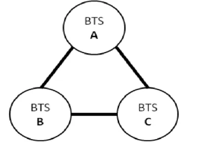
The great challenging tasks in GSM equipment environment, is to maintain efficiently the BTS, BSC, MSC equipment maintenance because, it has a great cost in technical aspect (Create and integrate new network planning in hardware and software level), economic aspect (cost reduction in maintenance) and environmental aspect (use of renewable energy through solar panels or wind power system) to increase a superior performance to mobile network communication provider. And other challenging work of maintenance, “is the coverage aspect in certain area, this make the RF engineer’s look for high altitudes and free of obstacles sites to reach larger distances, in traffic aspect, hotspots are focused with a BTS full equipped with radio channels in a limited and controlled RF radiation. And the BTS proximity is limited by interference in an urban area, because since there are a limited number of RF channels and they are repeated on and on, this make the BTS sites are allocated in a triangular grid pattern,
14 where it is possible divide to the three cells of each BTS that formed by the coverage of tree groups on antennas, disposed with 120º angle between then” (Pinheiro et al., 2010).
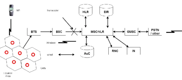
Figure 2 – The GSM Architecture (Mallikharjuna, 2012)1
The Figure 2 present the GSM architecture where we each component of equipment has its functionality like as,
• The “ Mobile Switching Center (MSC) Responsible for switching the voice or data connection to the mobile host” (Mallikharjuna et al., 2012).
• The “ Gateway Mobile Switching Center (GMSC) which can route the calls from Public Switched Telephone Network (PSTN)” (Mallikharjuna et al., 2012).
• The “Base Station (BS), is the gateway between the wireless network and wired network. It provides the wireless connection to the mobile subscribers within its coverage area (Cell). A set of base stations are connected to the MSC through a Base Station controller” (Mallikharjuna et al., 2012).
• The “Authenticating Center (AC or AuC) is a workstation system, which authenticates subscribers. AuC needs to access user information for authentication process so it is co-located with HLR” (Mallikharjuna et al., 2012).
15 • The “Equipment Identify Register (EIR) it is a database which stores information for the identification of mobile units” (Mallikharjuna et al., 2012). • The “PSTN this component refers to the regular wired line telecommunication network which is commonly accessed by landline calls” (Mallikharjuna et al., 2012).
The second generation of cellular technologies it also “covers the whole network architecture from radio access to core network. The acronym GERAN is more specific and stands for GSM/EDGE Radio Access Network. In practice this means the technology between mobile terminal and the base station” (Engineering, 2015).
The GERAN architecture is illustrated in Figure3, where we see the Base Transceiver Station (BTS) and the Base Station Controller (BSC) elements to communicate with the Core network travelling to the CS Core to get high rate of voice traffic communication and PS Core to get high rate of data traffic.
Figure 3 - GERAN system architecture da Internet (NSN 2013)2
The Figure 3 shows the communication relationships between “the GSM network components are described by a number of standardized interfaces. These interfaces can
2
Imagem retirada do site:
https://dspace.cc.tut.fi/dpub/bitstream/handle/123456789/22812/Developing%20a%20dimensioning%20model%20for%20NetAct% 20performance%20testing.pdf;sequence=1
16 be used for managing the data transfers or controlling the connections in mobility management” (Engineering, 2015).
To understand the interfaces of GERAN system, lest see the description:
• BTS contains transmitter and receiver equipment, such as antennas and amplifiers.
• BSC contains protocol functions for radio channel allocation, channel setup and management of handovers. Typically, one BSC handles hundreds of BTS.
• Um, an interface between MS and BTS, target to provide access to the network.
• Abis, an “interface between BTS and BSC. It is used for controlling the radio equipment and radio frequency allocation in the BTS. The Abis interface also carries synchronization information from the BSC to the BTS and MS” (Engineering, 2015).
• Iur-g, an interface between two BSCs.
• Gb, an “interface between GERAN and SGSN. The Gb interface enables communication between SGSN and MS” (Engineering, 2015).
• A/Ater, A is “an interface between BSC and CS-MGW. It is used for signaling and carrying traffic channels. Ater is an interface between BSC and transcoder, it carries the A interface information from the BSC leaving it untouched” (Engineering, 2015).
The 2G contains three major technology categories; GSM, GPRS and EDGE. The “GSM technology is dedicated to speech calls and GPRS and its successor EDGE to packet data. While these technologies start to be outdated, GSM still is one of the best options for speech, mainly because of its wide cell coverage and simple implementation” (Engineering, 2015).
17 2.1.2. The UMTS Network Communication System
The 3G network communication system based in “2G mobile network communication system, that have enabled voice traffic to go wireless. And it has been the features have helped 2G systems to spread rapidly around the world, with very high cellular phone penetration rates in many countries. The cellular networks have enabled certain types of communication to take place on a massive scale that previously were not possible or were at least severely limited” (Laiho et al., 2005).
With limited functionality in 2G makes the 3G “merge paging, cordless telephones, mobile terrestrial, and mobile satellite standards into a single unified standard. And video coding at Very Low Bit Rates(VLBRs), in the range of a few tens of kilobits per second, is becoming very attractive for a number of new applications, such as mobile video communication, video telephony on the PSTN, multimedia electronic mail, and remote sensing, and for interactive data bases” (Gill, Cosmas, & Pearmain, 2000).
The “ability to transport compressed audio and video over mobile links will open up new areas of opportunity for services not yet commercially developed and provide the incentive to migrate from GSM to UMTS networks. And communications can be provided rapidly where there is an urgent need, in the form of mobile terminals, without the costly overhead of cable provision” (Gill et al., 2000). This causes the huge growth of mobile subscribers worldwide during the last decade, backed by an increasing demand for higher transmission rates and flexible access to diverse services, makes telecommunication provider introduces very variable data rates on the air interface, as well as the independence of the radio access infrastructure and the service platform.
“That motivated significant research, standardization, and development in mobile communication systems, and the main objective of future wireless networks is to provide universal ubiquitous coverage across different radio technologies through a single terminal, while offering a rich range of services with variable bandwidth and QoS (quality of service), anytime, anywhere” (Al-Gizawi, Peppas, Axiotis, Protonotarios, & Lazarakis, 2005).
18 The following years were spent on optimizing UMTS system specifications, handset and network implementations, and mobile applications has been increasing in many kind of functionality and with increase of quality need for customers. The WCDMA has been able to bring tangible benefits to operators in terms of network quality, voice capacity, and new data service capabilities.
The 3G cellular networks communication system that has been standardized by “3rd Generation Partnership Project (3GPP) have already gained significant customer base in many countries. And the 3GPP feature was gradually deployed to the evolution from GSM to EDGE to 3G/WCDMA and HSPA, to enhancing network capacities, the 3GPP has played a key role in such wide-spread deployment that have already gone through several updates with respect to handling packet data connections” (Perälä, Barbuzzi, Boggia, & Pentikousis, 2009). And 3GPP technologies provide an excellent overview to “introduced High Speed Downlink Packet Access (HSDPA), a major enhancement to the downlink channel, with nominal peak data rates of 14.4 Mb/s. And, the uplink packet data connection was upgraded as well with the introduction of High Speed Uplink Packet Access (HSUPA). When used together, these enhancements form a technology referred to as HSPA” (Holma, Toskala, & Wiley InterScience (Online service, 2009).
And the 3GPP has an intent “to offer enhanced multimedia services to mobile users at high data rates, the systems are expected to be initially deployed in dense subscriber areas covered by GSM/GPRS (e.g., city centers, shopping malls) to augment the capacity and deployments of these existing GSM/GPRS networks to display the result. Hence, one of the critical features in the initial deployments of UMTS networks is the system functionality between UMTS and GSM/GPRS. Efficient inter-working between UMTS and GSM/GPRS systems will be crucial to provide continuous service coverage to dual-mode mobiles” (Saravanant, Sreenivasulu, Jayaram, & Chockalingam, 2007).
The “WCDMA networks were launched during 2002. By the end of 2005 there were 100 open WCDMA networks and a total of over 150 operators having frequency licenses for WCDMA operation. Currently, the WCDMA networks are deployed in Universal Mobile Telecommunications System (UMTS) band around 2GHz in Europe
19 and Asia including Japan and Korea. WCDMA in America is deployed in the existing 850 and 1900 spectrum allocations while the new 3G band at 1700/2100 is expected to be available in the near future. 3GPP has defined the WCDMA operation also for several additional bands, which are expected to be taken into use during the coming years” (Speed, Access, & Communications, n.d.).
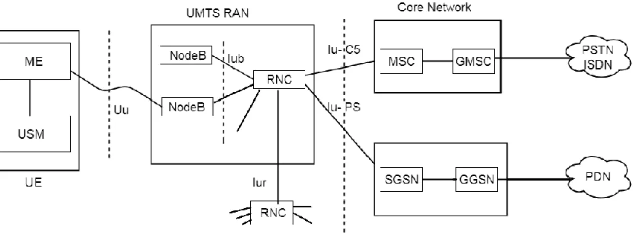
Figure 4 – The UMTS Architecture (RF WIRELESS, 2017)3
The Figure 4 present the UMTS architecture where we each component of equipment has its functionality like as,
• The user (UE) has very high-speed RF connection to the nearest local tower, and the high-speed connections is always ON, as long as mobile is powered up.
• The “Mobile Switching Center (MSC) Responsible for switching the voice or data connection to the mobile host” (Mallikharjuna et al., 2012).
• The “Gateway Mobile Switching Center (GMSC) which can route the calls from PSTN” (Mallikharjuna et al., 2012).
• The RNC performs radio specific tasks, such as it converts packets into radio frames and vice versa, manages the radio resources, and controls handover. • The “PSTN this component refers to the regular wired line telecommunication network which is commonly accessed by landline calls” (Mallikharjuna et al., 2012).
20 • The Gateway GPRS Support Node (GGSN) provides interworking with packet data networks and is connected with other core network nodes via an IP-based packet domain PLMN backbone network.
• The Integrate Service Digital Network (ISDN)
• The SGSN contains mechanisms for avoiding and handling overload situations. In an overload situation the SGSN can request the RNC to reduce any kind of signaling traffic as specified in TS.
The goal of 3G was to offer a greater spectral efficiency and bandwidth for growing telecommunication markets, and the Radio Access Network functionality are Similarly, as in GERAN, UTRAN is the radio technology used between mobile terminal and base stations.
The 3G offered a huge improvement in data rates when compared to 2G, but “it also increased complexity on the network planning side. The reason for complexity is that in 3G, every user is generating interference for the other users, because all share the common frequency band. Another 3G-specific thing is cell breathing, this means that the cell size is increasing and decreasing depending on the number of users in the cell” (Engineering, 2015).
21 Figure 5 - UTRAN system architecture (NSN 2013)4
The Figure 5 shows the control plane in UTRAN includes the application protocols and the signaling bearers, which transport the control information to describe the UTRAN network element like as:
• NodeB means the same as the base station. “It’s task is to convert the data flow between Iub and Uu interfaces and participate to radio resource management”.(Engineering, 2015)
• Radio Network Controller (RNC) owns and controls the radio resources in its domain. It also works as a connection point for core network services. • Uu, is the WCDMA radio interface, through Uu UE can access the network. • Iub, is a logical interface between a NodeB and a RNC.
• Iur, is an interface that enables soft handovers between RNCs from different manufacturers.
• Iu-CS connects UTRAN to CS core network and enables circuit switched mobile calls.
4
Imagem retirada do site:
https://dspace.cc.tut.fi/dpub/bitstream/handle/123456789/22812/Developing%20a%20dimensioning%20model%20for%20NetAct% 20performance%20testing.pdf;sequence=1
22 • Iu-PS connects UTRAN to PS core network and enables access to Internet.
The presented integration architecture for UMTS and WLAN. The “WLANs in hotspot areas form micro-cells within UMTS macro-cells. The architecture allows a mobile node to maintain data rate (PS) connection through WLAN and telephony voice rate (CS) connection through UMTS in parallel. This is especially attractive because WLAN is currently used primarily for high-speed best-effort data service” (Speed et al., n.d.).
23 2.1.3. The LTE Network Communication System
The demand for high speed internet for mobile communication system increased sharply, and the need for mobile broadband consumer access is happening, mostly due to the HSPA and LTE.
The “Network optimization is one of the key parts in the life cycle of mobile systems. For second- generation (2G) mobile networks, a series of standardized procedures have been defined for wireless network planning and optimization, while for third-generation (3G) mobile networks, researchers, and engineers are testing and improving the network planning and optimization methods/tools, both of them 2G and 3G mobile systems, network optimization should involve base station maintenance, signaling, testing, adjustment, data collection, and analysis functions to improve coverage and reduce interference. However, the deployment and optimization of mobile networks are very complicated and challenging engineering tasks that require a comprehensive systematic approach. Conventional procedures usually are time consuming, require a lot of resources and man- power to achieve the goal. In future mobile networks, wherein multiple types of cells (e.g., macro, micro, pico, and even femto) will coex- ist, an increasing number of parameters need to be taken into account in network optimization, so the challenges become much more intensive.” (Hu et al., 2010).
The optimization of mobile communication networks is becoming a different factor that applies in a methodology for the configuration of mobile communication networks, because it`s a critical aspect in technical point of view (Create and integrate new network planning in hardware and software), economic (cost reduction in maintenance) and environmental (use of renewable energy through solar panels or wind system). Owing to the fact that, the optimization of the methodology of configuration of the mobile communication networks has been a constant concern, for both companies which provide telecommunication services, and mobile telecommunications operators.
The Ips Packet Optimization Network Architecture are deployed to develop of more efficient network architecture that concern in optimization of methodology of configuration of mobile communication networks to increased data rates, improved spectrum efficiency, improved coverage, and reduced latency. Those will allow carriers
24 to provide more data and voice services over a given bandwidth and reduce the operator cost in variety of traffic scenarios and automatization in sites on RNC and BSC.
The “LTE has a ‘flat’, all-IP based core network with a simplified architecture, open interface and fewer system nodes. Indeed, the all-IP based network architecture together with the new Radio access Network (RAN) reduces network latency, improved system performance and provide interoperability with existing 3GPP and non-3GPP technologies” (Sheriff, 2011). Within “3GPP, all-IP based core network architecture is now known as Evolved Packet Core (EPC). EPC is the result of standardization work within 3GPP which targeted to convert the existing System Architecture Evolution
(SAE) to an all-IP system” (Holma, Kristensson, Salonen, & Toskala, 2008).
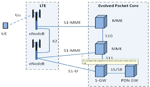
Figure 6 – The LTE Architecture
The Figure 6 depicts the internals LTE network. The UE has very high-speed RF connection to the nearest local tower, and the high-speed connections is always ON, as
25 long as mobile is powered up. The LTE is an all IP infrastructure with service priority built in audio and video are given priority. All necessities like Authentication, security and IP address are validated
The “evolved RAN consists of the LTE base station (eNodeB) that interfaces with the UE. The eNodeB contains the PHY, Media Access Control (MAC), Radio Link Control (RLC), and Packet Data Control Protocol (PDCP) layers. Therefore, the eNodeB performs some tasks such as resource management, admission control, scheduling and enforcement of negotiated UL Quality of services (QoS)” (Fernando & Pepinosa, 2013).
The “Serving Gateway (SGW) guides and forwards user data packets. Furthermore, during inter-eNodeB handover SGW acts as the mobility anchor for the user plane. It can also act as an anchor for mobility between LTE technology and other 3GPP technologies. When the UE is in idle state, the SGW terminates the DL data path of the UE and triggers paging when DL data arrives for the UE” (Holma et al., 2008).
The “Mobility Management Entity (MME) handles Control Signaling, for UE tracking and paging procedure that includes retransmissions” (Holma et al., 2008). MME is also involved in the bearer activation/deactivation process. “In addition, MME can choose the SGW for a UE at the initial attach and at time of intra-LTE handover involving core Network (CN) node relocation. MME can interact with the Home
Subscriber Server (HSS) so as to authenticate the user” (Holma et al., 2008).
The Packet Data Network Gateway (PDN GW) is a point of exit and entry of traffic for the UE. PDN GW performs packet filtering and acts as the anchor for mobility between 3GPP and non-3GPP technologies such as WiMAX and 3GPP2. (Holma et al., 2008).
The network upgrading to LTE generation evolve changes in mobile communications have traditionally been evolutionary path to higher speeds and reduced latency to networks, the deployment and design of LTE is based on 3GPP family of cellular network that dominate by GSM, General Packet Radio Service (GPRS) and Enhanced Data rate for GSM Evolution (EDGE) as well as WCDMA and HSPA.
26 Figure 7 – The LTE Upgrading flow
The LTE network evolution is that “deploy hybrid packet/circuit switched networks, and other evolution, is in uses of the advanced new radio interface such as all IP environment architecture, to harness the full potential of LTE it requires an evolution from the existing network architecture ta a simplified. This evolution has advantages to operator`s to include reduced costs for variety of services, blended applications combining voice, video and data services plus interworking with other fixed and wireless networks” (Fernando & Pepinosa, 2013).
“Since the design of LTE is based on UMTS/HSPA family of standards, it will obvious enhance the capabilities of the existing cellular network technologies to delivery broadband services which were accustomed to fixed broadband networks. In other words, LTE will unify voice-oriented environment mobile networks with the data centric services possibilities of the fixed internet to the operator’s point of view, the smooth upgrading of the existing networks to LTE will allow the introduction of LTE’s all-IP concept progressively. As such operator will be able to retain the value of its existing voice-based service platforms at the same time getting the benefit of high performance in data services delivered by LTE network” (Fernando & Pepinosa, 2013).
The one of goal of LTE has been to provide even higher data rates than 3G and improve the spectrum efficiency while lowering the network operation costs. As a difference to older technologies, in “LTE all the data is IP based packet data, which also means that LTE does not have Circuit Switched (CS) Core. At the moment this also creates a drawback for LTE. When a user establishes or receives a call in an LTE
27 network, the mobile device has to do a CS Fallback procedure and switch back to 2G or 3G network to be able to do so. In future this is changing with the Voice over LTE (VoLTE) technology which enables IP based calls in the LTE network” (Engineering, 2015).
The LTE introduced Evolved Packet Core (EPC) which “should handle the data traffic efficiently in terms of performance and costs while having a simplified flat architecture. One of the major improvements in EPC is the separation of the user and the control planes, which makes the network scaling more independent and easier for the operators” (Engineering, 2015).
The LTE network and EPC can be seen in Figure6 below where we can explain each element in Figure 8.
Figure 8 - LTE system architecture (NSN 2013)5
The Figure 8 shows the control plane interfaces in LTE architecture as important way to understanding the function of the elements in the network. The control plane
5
Imagem retirada do site:
https://dspace.cc.tut.fi/dpub/bitstream/handle/123456789/22812/Developing%20a%20dimensioning%20model%20for%20NetAct% 20performance%20testing.pdf;sequence=1
28 interfaces also describe functionality between two network elements and it`s ease to understanding the relations in the network like as:
• Evolved NodeB (eNodeB) is “the LTE element equivalent to BTS and NodeB but differs in the sense that eNodeB has radio resource control, radio mobility management and full layer 2 protocol support features”
(Engineering, 2015).
• Mobile Management Entity (MME) is used for the control plane functions related to subscriber and session management.
• Serving Gateway (SGW) is used as a “connection point of the packet data to-wards Evolved UMTS Terrestrial Access Network (E-UTRAN). In practice this means that the S-GW enables mobility between E-UTRAN and other 3GPP technologies” (Engineering, 2015).
• Packet Data Network Gateway (PDN GW) is functioning similarly as SGW and works as a termination point of the packet data interface towards the packet data network.
• S10 is an interface between MME and another MME; it is used between MMEs for MME relocation and MME to MME information transfer.
• S11 is an interface between MME and SGW, its target is to function as a reference point between MME and Serving GW.
• S5 or S8 are interfaces “between SGW and PGW. S5 provides user plane tunneling and tunnel management between SGW and PGW. S8 is an inter-PLMN reference point providing the user and control planes between the SGW in the visitor PLMN and the PGW in the home PLMN” (Engineering, 2015).
• S1-U is an interface “between eNodeB and SGW, and it is used between E-UTRAN and Serving GW for the per bearer user plane tunneling and inter eNodeB path switching during handover” (Engineering, 2015).
• S1-MME is an interface “between eNodeB and MME, it is a reference point for the control plane protocol between E-UTRAN and MME” (Engineering, 2015).
• X2 is an “interface between two eNodeBs, it can be used for signaling and handling radio resources between the base stations” (Engineering, 2015).
29 • Uu is an “interface between eNodeB and UE, its target is to provide data
transfer between eNodeB and UE” (Engineering, 2015).
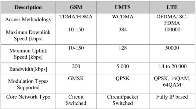
The GSM, UMTS and LTE are similar in many ways in the sense that they inherit most of the elements implemented in the “GSM/GPRS and EDGE architecture while changing the names of the elements. A Major similarity is the fact that they all implement radio access points and they use cellular technology; another similarity is that they all employ the use of the HLR as the subscriber database although it is called the Home Subscriber Server (HSS) in LTE. The differences between most of the technologies are based on the evolvement of the core elements and the access methodologies, bandwidths and modulation types. The table below is used to give a better comparative analysis between the technologies” (Ochang & Irving, 2016).
Table 1 – Comparison of GSM, UMTS and LTE features (Ochang 2016)6.
Description GSM UMTS LTE
Access Methodology TDMA/FDMA WCDMA OFDMA/
SC-FDMA Maximun Downlink Speed [kbps] 10-150 384 100000 Maximun Uplink Speed [kbps] 10-150 128 50000 Bandwidth[kbps] 200 5 000 1.4 to 20 000 Modulation Types Supported GMSK QPSK QPSK, 16QAM, 64QAM Core Network Type Circuit
Switched
Circuit/packet Switched
Fully IP based
I must conclude that the mobile network communication system mainly cellular technologies, have experienced a tremendous growth and change in their architectural design and this change has been very significant in the core of the network. The “network core has fully evolved from a circuit switched core to an all IP based core which means that with the advent of future cellular technologies, IP packets can be used to carry cellular network traffic therefore enhancing traffic management and providing
6table taken from the:
30 better quality of service” (Ochang & Irving, 2016). And based on this analysis this means that they will be advanced support for services such as multimedia streaming. Integration with other telecommunication infrastructure such as Voice over Internet Protocol (VoIP) will provide an interesting area of research. Therefore, further research can be carried out in other to provide a clear overview of how VoIP can be integrated into the IP core of advanced future cellular technologies.
31 2.1.4. Core Network
The core network (CN) “means the backbone of the telecommunication networks. It has also evolved during the technological advancement from 2G to LTE and the direction at the moment is towards the liquid core, meaning virtualization and cloud services. The key features of core networks are aggregation, authentication, call control or switching, charging, service invocation and gateways to other services” (Engineering, 2015).
The CN introduced the different ways in architecture of functionalities in each technology (GSM, UMTS and LTE) comparing both of them. The “GSM core architecture relied on circuit switching until the GPRS was introduced; it added packet switching to circuit switching, which enabled the transportation of packets without establishing dedicated circuits. When UMTS was released, it evolved some network elements but mainly it kept this dual domain concept in the core network. And the LTE has introduced an evolved packet core and by doing so, it has simplified the core network architecture” (Engineering, 2015).
The Figure 9 shows the circuit and packet domains.
Figure 9 - Circuit and packet domains (NSN 2013)7
The Figure 9 shows the circuit and packet domains where the registers and PS/CS core network elements are described below.
7
Imagem retirada do site:
https://dspace.cc.tut.fi/dpub/bitstream/handle/123456789/22812/Developing%20a%20dimensioning%20model%20for%20NetAct% 20performance%20testing.pdf;sequence=1
32 • Circuit Switch Media Gateway (CS-MGW) is “a node which handles CS connection capacity and handles all physical connection matters”(Engineering, 2015).
• Mobile Switching Center (MSC Server) is “a switch that serves the UE in its current location for circuit-switched services. MSC also contains visitor location register (VLR) database” (Engineering, 2015).
• Gateway MSC (GMSC Server) is “the switch at the point where public land mobile network (PLMN) is connected to external circuit switched networks. All incoming and outgoing circuit switched connections go through GMSC” (Engineering, 2015).
• Authorization, Authentication and Accounting (AAA) is “a register that authenticates and authorizes the subscriber’s network access. AAA is also responsible for subscriber billing” (Engineering, 2015).
• Equipment Identity Register (EIR) “contains information about terminal equipment and can be used for blocking specific terminals from network” (Engineering, 2015).
• Home Subscriber Server / Authentication Center (HSS/AuC) presents “the registers such as home location register (HLR). The function of HSS is to provide information about user’s service priorities and data rates. AuC part of the HSS is used for generating security information from user identity keys, which then is used for network terminal authentication” (Engineering, 2015).
• Serving GPRS Support Node (SGSN) has a similar functionality as MSC but is used for packet switched services.
• Charging Gateway Node (CGN) collects charging data from PS domain elements and relays them to the billing center to be post processed.
• Gateway GPRS Support Node (GGSN) PS counterpart for GMSC.
• Border Gateway (BG) is a gateway which enables roaming between two separate PS domains belonging to separate network.
• Public Switched Telephone Network (PSTN) means the traditional wired tele-phone network.