Department of Information Science and Technology
Find Me! – an Indoor Location System
Stuart Costa Martinho
Master in Telecommunications and Computer Engineering
Supervisor
João Carlos Ferreira, Assistant Professor, ISCTE-IUL
Co-Supervisor
Ricardo Pontes Resende, Assistant Professor, ISCTE-IUL
Abstract
This work presents an approach of combining location information from beacons and local building information to give location and guidance to a user inside a complex building. This information can help user’s orientation into unknown buildings through a smartphone. Beacons are installed on the building and emit signals that are converted to user current position, related with Bluetooth’s range. The building data is generated by Building Information Modeling (BIM) model which is going to be used as input data of this project. This system is based on a mobile App (Find Me!), for Android OS (Operating System), which captures the Bluetooth Low Energy (BLE) signals, coming from the beacon(s), and shows, through a map, the location of the user ‘s smartphone, and his destination, and guides him to the desired destination.
Keywords: Guidance, Beacons, BIM Model, User location, Mobile App, BLE, destination.
Resumo
Este trabalho visa abordar uma combinação entre localização, proveniente de informação retornada por Beacons, com informação de edifícios de larga escala de modo obter a localização do utilizador e de seguida conseguir guiá-lo, dentro do edifício em que este se encontra. Deste modo, este projeto conseguirá ajudar estes utilizadores que se encontram dentro de um edifício que desconhecem, com orientações, através de um smartphone. São instalados Beacons no edifício, estes emitem sinais que, após recebidos pelo smartphone, irão ser convertidos em localização atual do utilizador. Este processo está relacionado com o raio de cobertura de sinais Bluetooth. Os dados respetivos ao edifício são gerados pelo modelo Building Information Modeling(BIM), estes irão ser usados como dados de entrada deste projeto. Este sistema baseia-se numa aplicação móvel (Find Me!), desenvolvida em Android como sistema Operativo, que captura sinais Bluetooth Low Energy (BLE), proveniente dos beacons, e apresenta, através de um mapa, a localização e o destino do utilizador, guiando-o até ao destino pretendido.
Palavras-chave: Orientação, Beacons, modelo BIM, Localização do utilizador, Aplicação Móvel, BLE, destino.
Acknowledgments
I would like to express my very great appreciation to my Supervisor, João Carlos Ferreira, and to my Co-Supervisor, Ricardo Pontes Resende, who provided great guidance and objective reviews to this project.
My special and sincerely thanks to my mother and father, Orquidea and Francisco, who always worked a lot to give me all the tools that I needed to finish my graduation. Without them, it would not be even possible to conquer my objectives.
To my girlfriend who gave me enthusiastic encouragement in every moment that I needed it. Also, to my colleague Vicente Pereira, and students from Architecture that gave me precious contributions to this project.
My sincere thanks to ISCTE-IUL Maintenance and ISCTE-IUL Technology and Information departments who also gave me invaluable help in our ISCTE-IUL pilot tests. Finally, a huge thanks to Ricardo Vilas Boas that made possible the reconcile between my job and the available time to finish this project.
Contents
Abstract ... i Resumo ... iii Acknowledgments ... v Contents ... vii List of Figures ... xiList of Tables ... xvi
List of Acronyms ... xviii
Chapter 1 Introduction ... 1
Motivation and Framework ... 1
Objectives ... 2
Project Outline ... 2
Chapter 2 Literature Review ... 3
Indoor Location Technologies ... 3
2.1.1 QR Code ... 3 2.1.2 NFC ... 4 2.1.3 GPS ... 5 2.1.4 WiFi Triangulation ... 5 2.1.1 Beacon ... 6 2.1.2 IL Technologies Comparison ... 7
Building Information Models ... 8
2.3.3 Mobile Application Development Verdict ... 12
The A* Path Finding Algorithm ... 13
Database ... 14
2.5.1 External Database ... 14
2.5.2 Local Database ... 14
2.5.1 Relational Database Management Systems ... 14
2.5.2 Data Storage Verdict... 15
Related Projects ... 15
2.6.1 ILS based on QR Code technology ... 15
2.6.2 ILS based on NFC technology ... 16
2.6.3 ILS based on WiFi triangulation ... 17
2.6.4 ILS based on Beacon technology ... 18
Chapter 3 Find Me! Conceptual Modules ... 21
Find Me! Overview ... 21
3.1.1 User Roles ... 23
System Architecture ... 28
3.2.1 Beacon Installation Process ... 30
3.2.2 Mobile App Back End ... 31
3.2.3 Mobile App Front End ... 32
Chapter 4 Find Me! Implementation ... 33
Beacon Installation Process ... 33
4.1.1 Beacons ... 33
4.1.2 Beacon Physical Placement ... 35
4.1.3 BIM Model ... 49
Find Me! Mobile App ... 51
4.2.1 Mobile App Back End ... 52
4.2.3 Entities Relation ... 64
Chapter 5 Implementation at the ISCTE-IUL Campus ... 65
Beacon Installation Process ... 65
Implementation Results ... 68
5.2.1 Setup ... 69
5.2.2 Find Me! Tests and Results ... 70
Chapter 6 Conclusion ... 91
Future Work ... 92
List of Figures
Figure 2-1 - QR code example with "Hello World" information as content. ... 3
Figure 2-2 - NFC chip example [4]. ... 4
Figure 2-3 - Beacon device. ... 6
Figure 2-4 - Estimote Proximity Beacon (left) and BlueCats AA Beacon (BC-313) (right). ... 7
Figure 2-5 - 3D section views of the BIM model of ISCTE-IUL’s Building 1 – Sedas Nunes... 9
Figure 2-6- Hand-drawn floor plan of an apartment (left) and a Schematic cross-section of a multilevel building (right). ... 10
Figure 2-7 - The Android software stack/architecture [15]. ... 12
Figure 2-8 - A* algorithm process [16] ... 13
Figure 2-9 - Positioning by QR_STU ... 16
Figure 2-10 - ILS App’s Flow Chart [20] ... 17
Figure 2-11 - The test bed of the experiment. ... 17
Figure 3-1 - Find Me! use cases diagram. ... 23
Figure 3-2 - Destination insertion mode options. ... 24
Figure 3-3 - FIND ROOM option. ... 24
Figure 3-4 - FIND FAST options. ... 25
Figure 3-5 - Orientation View example. ... 25
Figure 3-6 - Elevator button selected. ... 26
Figure 3-7 - FIND PHOTOS view ... 27
Figure 3-8 – Screenshot example of Current Floor (left) and Destination Floor (right). ... 27
Figure 3-9 - Find Me! architecture. ... 29
Figure 4-1 - NearestBeacons scan values example. ... 36
Figure 4-2 - Floor no 0, 1 and 2 (left to right) with placed beacons. ... 37
Figure 4-3 – Beacon Placement practical example. ... 37
Figure 4-8 - Test Case 2 values, Floor 2, user position (left), NearestBeacons
(right). ... 40
Figure 4-9 - Test case 3 layout. Floor 0 (left), floor 1 (middle) and floor 2 (right). ... 41
Figure 4-10 - Test Case 3 values, Floor 1, user position (left), NearestBeacons (right). ... 41
Figure 4-11 - Test Case 3 values, Floor 2, user position (left), NearestBeacons (right). ... 42
Figure 4-12 - Test Case 3 values after configuration changes, Floor 0(left) and Floor 1(right), NearestBeacons... 42
Figure 4-13 - Test Case 3 values after configuration changes, Floor 2, NearestBeacons... 43
Figure 4-14 - Test case 4 layout. Floor 1 (left) and Floor 2 (right). ... 43
Figure 4-15 - Test Case 4 values, Floor 1, user position (left), NearestBeacons (right). ... 44
Figure 4-16 - Test Case 4 values, Floor 2, user position (left), NearestBeacons (right). ... 44
Figure 4-17 - Beacons Placement rules diagram. ... 45
Figure 4-18 - Beacons Distance Rules diagram. ... 47
Figure 4-19- Creating Estimote Account ... 47
Figure 4-20 - Beacon Name configuration ... 48
Figure 4-21 - Configure Protocol and Broadcast Packets ... 49
Figure 4-22 - Main Dynamo script for beacon and door/room tables production. ... 50
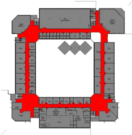
Figure 4-23 - Floor plans generated from the BIM model for user visualization (left); internal app pathfinding algorithm support with walkable areas in red (right). ... 51
Figure 4-24 - Estimote dependency ... 52
Figure 4-25 – Estimote API, Connect method. ... 53
Figure 4-26 - Estimote API, Monotoring Beacons method ... 53
Figure 4-27 - Room and Beacon tables structure ... 55
Figure 4-28 - Room CSV data example. ... 55
Figure 4-29 - Beacon CSV data example. ... 56
Figure 4-32 - Example of Map floor with marked walkable path in red. ... 58
Figure 4-33 - Map view screen description ... 60
Figure 4-34 – Image View set process. ... 61
Figure 4-35 - Choose Destination options ... 62
Figure 4-36 – FINDROOM option. ... 63
Figure 4-37 - FINDFAST option ... 63
Figure 4-38 - Sequence Diagram of Orientations Process ... 64
Figure 5-1 - Maps of floors 0,1 and 2 of the pilot building - Edificio 1. ... 65
Figure 5-2 - Floor 0 with beacons placement. ... 66
Figure 5-3 - Floor 1 with beacons placement. ... 67
Figure 5-4 - Floor 2 with beacons placement. ... 67
Figure 5-5 - Smartphone Huawei P8 gra-l09 ... 69
Figure 5-6 - Estimote Proximity Beacon ... 70
Figure 5-7 – Test 1 - Floor 1 map with current (yellow) and destination (red) locations marked. ... 71
Figure 5-8 - Test 1 - Floor 1 with paths possible options marked. ... 72
Figure 5-9 - Test 2 - floor 1 with the current location (yellow). ... 73
Figure 5-10 - Test 2 - floor 2 with the destination (red). ... 73
Figure 5-11 - Test 2, subtest 1 - floor 1 with path options. ... 74
Figure 5-12 - Test 2, subtest 1 - floor 2 with path options. ... 75
Figure 5-13 - Test 2, subtest 2 - floor 1 with path option. ... 76
Figure 5-14 - Test 2, subtest 2 - floor 2 with path option. ... 76
Figure 5-15 - Test 3 - Floor 1 map with current (yellow) and destination (red) locations marked. ... 77
Figure 5-16 - Results of Test case 1, Beacon ED1P1E intersection. ... 78
Figure 5-17 - Results of Test case 1, Beacon ED1P1F intersection. ... 79
Figure 5-18 - Results of Test case 1, Beacon ED1P1G intersection ... 80
Figure 5-19 - Results of Test case 1, Beacon ED1P1H intersection. ... 81
Figure 5-20 - Results of Test case 2, Subtest1, Beacon ED1P1D intersection. .. 82
Figure 5-25 - Results of Test case 2, Subtest2, Beacon ED1P1E(left), ED1P1F(middle) and ED1P1G(right) intersection. ... 86
Figure 5-26 - Results of Test case 2, Subtest2, Beacon ED1P2G (left), ED1P2H (middle), ED1P2A (right) and ED1P2B (bottom) intersection. ... 87
Figure 5-27 - Results of Test case 3, Beacon not intersected message. ... 88 Figure 5-28 - Results of Test case 3, Beacon ED1P1H intersection. ... 89
List of Tables
Table 2-1 - Pros and Cons of different ILS devices [10] ... 7 Table 2-2- Benefits of MYSQL and Oracle [19] ... 14 Table 4-1 – Broadcasting Power values converted to Maximum Range in meters.[24] ... 34
List of Acronyms
3G 3rd Generation
4G 4th Generation
5G 5th Generation
AOA Angle of Arrival
AP Access Point
API Application Program Interface BIM Building Information Model BLE Bluetooth Low Energy CSV Comma-Separated Values
DB DataBase
GPS Global Positioning System
ID Identifier
IDE Integrated Development Environment
IL Indoor Location
ILS Indoor Location System INS Indoor Navigation System IPS Indoor Positioning System
ISCTE Instituto Superior de Ciências do Trabalho e da Empresa IUL Instituto Universitário de Lisboa
NFC Near Field Communication
OS Operating System
PFA Path Finding Algorithm PNG Portable Network Graphics
QR Quick Response
RDBMS Relational Database Management System RSS Received signal strength
RSSI Received Signal Strength Indicator SDK Software Development Kit
TOA Time of Arrival
URL Uniform Resource Locator WiFi Wireless Fidelity
Chapter 1 Introduction
Motivation and Framework
In modern buildings, people easily and frequently get lost, mostly because the building layout is complex, orientation signs are insufficient in number and clarity, and the environmental cues such as sunlight are missing. People usually resort to wander and explore on their own, then ask for directions and sometimes get lost again. This situation is more usual in big and complex buildings such as hospitals, airports, shopping’s, and museums. This people’s life problem can be easily solved by an Indoor Location System (ILS).
ILS, also known as Indoor Positioning Systems, serve the purpose of finding an electronic device inside a building, typically with a simple smart device: phone, tablet or watch. The method of finding the device can be implemented via Bluetooth, infrared, magnetic field and/or WiFi. When the smart device connects to some of the Indoor Location devices, the system can store that data and takes many conclusions about that. An example of an Indoor Location technology is Beacon Technology. A beacon is a device that broadcasts a Bluetooth Low Energy (BLE) signal in a limited and configurable range. This signal can be interpreted as the location of the person inside of a building, without the need of Internet.
Most people have their own smartphone these days so the best and easiest way to help with the orientation is through a mobile App such as the Find Me! App. This software's function is to show on a map, where the user is and how to get to the selected destination, guiding him until he reaches it. The most important and crucial parts of Find Me! App is the user’s current location (from the beacon) and the desired user’s destination. Having these two locations, as data, a Path Finding Algorithm (A* Search Algorithm Type [2]) calculates the shortest way between these points and draw it on a map with the goal of guiding the user to the selected destination. When the user intersects another beacon region, the drawn path is updated with a new user’s current location.
Objectives
The objective of this project is to create an ILS mobile App that gives guidance to the user, giving the right directions until the user reaches the desirable point. The proposed work uses BLE beacons location information, indoor maps in BIM format floor plan, and routing algorithms in a mobile device. This proposal is applied to ISCTE-IUL university campus as a validation approach, and there is an intention of real usage of this work.
Project Outline
This project is organized as follows:
- Chapter 1 Introduction: describes the motivation and the defined objectives of this project are described;
- Chapter 2 Literature Review: provides the validation of state of the art technologies, and their descriptions;
- Chapter 3 Find Me! Conceptual Modules: describes the user roles and the system architecture of this project;
- Chapter 4 Find Me! Implementation: provides the implementation process of the system architecture mentioned in Chapter 3;
- Chapter 5 Implementation at the ISCTE-IUL Campus: evaluates the Find Me! project, applied to the ISCTE-IUL Campus;
- Chapter 6 Conclusion: concludes this project approach and the features that can be done/improved in the future.
Chapter 2 Literature Review
In this section, we present the technologies and approaches applied to this project, which include the description of available Indoor Location Technologies; the description of the BIM model; the presentation of available technologies to develop a mobile App; an overview of different types to implement a Data Base; a description of Path Finding Algorithm, which will be applied to this project approach; and finally an explanation about different ways and IL technologies used in related ILS projects.
Indoor Location Technologies
In this section, we describe the available IL devices [1] that can be integrated into our project proposal. Firstly, we start with a brief description of the technology and, based on that, we conclude it with a verdict.
2.1.1 QR Code
The Quick Response code (QR code) [2], invented in 1994 in Japan, is a two-dimensional barcode that holds a high capacity data storage. One QR code can store more than 7089 characters, which, compared to a regular barcode that only stores 20 digits, is much superior. It can be read/scanned by a smart device through his camera on both dimensions, vertically or horizontally. If a QR code is partially destroyed/degraded (but not more than 30% of its content) can be read as well. Figure 2-1 shows an example of a QR code.
combination of characters. For example, if the user creates a QR code with the string “AB” and another code with just “A”, both of them will be completely different.
An ILS system applied with this technology is based on QR codes identification, which is located in several places in the building. Having these QR codes located at different positions in the building, allows users to determine, by reading through a smart device camera, their current location.
QR code Verdict
For the perspective of the building management, QR code technology is cheap because the codes can be simply printed in a paper. This technology holds high accuracy in terms of Indoor Location. In terms of User usability, the user needs to switch on the smart device camera and look for the closest printed QR code to know his current location – needs to do a manual location recognition. Comparing to other devices, this technology has the worse usability.
2.1.2 NFC
Near Field Communication (NFC) technology [3] is based in tags that have chip content and NFC readers. The communication of these two components consists of radio waves transmission (of 13.56 MHz) between NFC readers and NFC tags. Usually, an NFC tag holds a small distance radio-frequency, and thus, to scan a tag successfully, the NFC reader needs to be close to it. A smart device work as a NFC reader. NFC chip can store and also send, to the NFC reader, approximately 8Kb of data. Figure 2-2 shows a NFC chip example.
NFC Verdict
The data transmission between NFC reader and the NFC tag is fast and the price of each tag can be cheap so the budget for the ILS concept is not expensive neither hard to implement. To get the user’s current location, there is a need to get the smartphone close to the NFC tag which decreases the user usability, when using NFC technology in an ILS approach.
2.1.3 GPS
Global Position System (GPS), developed by the USA, in the middle of 1973, to improve the navigation systems. It is based on radio navigation signals that come from 24 GPS satellites. All the satellites send radio signals that provide location, status and precise time to the GPS receiver A device with GPS receiver/reader enabled, can interpret the signal and calculate the distance from each satellite and translate into a distance from four satellites (at minimum). Then uses geometry to determine the device location on earth. This technology applies to both Indoor and Outdoor Location device.
GPS Verdict
GPS is the best location technology for outdoors systems, but for ILS has the negative way of not having a precise location. Inside of the building, it cannot locate where is the device in a specific room.
2.1.4 WiFi Triangulation
Geometric properties of triangles, consists in hot-spots that are physical implemented in several fixed places. Each of them provides the received signal strength (RSS), the angle of arrival (AOA) and the time of arrival (TOA). When a device intersects one or more of these hot-spots, calculates the distances between the target place and the hot-spots and determine, by triangulation, the position of the device. The Position calculation method requires a data service that accesses the packets triangulation sent by each hotspot and determines the final position of the device.
confusing to handle. Having internet access and data transfer as the main required points, when one of these requirements is not available, the entire ILS system is compromised.
2.1.5 Beacon
A Beacon is a small Bluetooth Radio Transmitter that repeatedly broadcasts synchronous Bluetooth Low Energy (BLE) [5] signal in a restrict region/area. Each signal contains configurable data that can be received by a smart device. A beacon example can be observed in Figure 2-3 .
Figure 2-3 - Beacon device.
Estimote Beacon
It was implemented by Estimote, Inc - a company founded in 2012 by Jakub Krych and Łukasz Kostka, graduates from Jagiellonian University and AGH University of Science respectively. Nowadays, Estimote sells five types of products [6]: Location UWB Beacon, Location Beacon, Proximity Beacon, Sticker Beacon, and Video Beacon.
The most appropriated Estimote product to use in an Indoor Location concept is the Proximity Beacon. This device holds an average of 2-3 years of battery life and a configurable range of maximum 70 meters in open field.
BlueCats Beacon
In 2011, BlueCats was founded by Cody Singleton, Kurt Nehrenz and Nathan Dunn in USA and Australia. Indoor location devices are the core of this company. There are 3 types of beacons available on the marked: AA Beacon(BC-313) [7], Coin Beacon[8] and USB Beacon[9].
The most designated BlueCats product for complement this project is the AA Beacon (BC-313). This indoor location device holds waterproof and a battery life of maximum 5 years depending on the device performance.
Beacons are the most recent indoor location technology, it is easy to configure and to maintain. It has its own API for the developers that want to implement an ILS. The security and Privacy of the users are safe, and the cost of each equipment is not expensive. Both beacon types, Estimote and BlueCats, have very similar characteristics so we are sure that both would fulfill all the requirements of this project. Since the price and the characteristics of both beacons are similar, we chose the Estimote beacon because the design of the product holds a better look. Figure 2-4 shows the design of both products, Estimote Proximity Beacon and BlueCats AA Beacon (BC-313).
Figure 2-4 - Estimote Proximity Beacon (left) and BlueCats AA Beacon (BC-313) (right).
2.1.6 IL Technologies Comparison
In this section, we discuss the pros and cons of an ILS using the different indoor location devices that were referred in section 2.1. Table 2-1 outlines the pros and cons, considering the ILS characteristics of each IL device.
Table 2-1 - Pros and Cons of different ILS devices [10]
QRCode NFC GPS WiFi Beacon
Accuracy of Tracking High High Low Low High Effort to Maintain Easy Difficult Difficult Easy Easy Industry Uptake Medium Medium Low High High Security and Privacy Medium High High Medium High Install, Maintenance Cost Low Low High High Medium
In this table, we are evaluating the following categories:
- Industry Uptake: with a scale of Low, Medium, and High, this parameter shows how much the ILS is acquired by customers in the global market;
- Security and Privacy: with a scale of Low, Medium, and High, this parameter shows how much the level of Security and Privacy that this ILS can provide to the system; - Install, Maintenance Cost: with a scale of Low, Medium and High, this parameter
shows the installation and maintenance cost level that the ILS needs.
Comparing all the evaluated categories from Table 2-1, Beacon technology, which holds the best average between Pros and Cons, is going to be chosen to complement this ILS approach.
Building Information Models
The Building Information Model, or BIM, is a 3D description of buildings which associate information with the geometry of the building and its contents such as fixings, furniture or spaces. As an example, a parametrized BIM model is aware that a specific door is a double door, glass made, has level 1 fire-rating, connects corridor 1S to room 1S04, opens to the room, on the left-hand-side, etc. ISCTE-IUL’s facility management office has been developing a BIM model which is being used to feed maps, room listings, and locations, as well as beacon’s locations. This proves a significant advantage because since the BIM models are data-based, can be queried and updated (currently not in real time) with information to and from the App. Moreover, BIM is not only a model but also a new process of work in Architecture, Engineering, and Construction (AEC). This very traditional and conservative industry is very siloed: information does not flow between stakeholders, such as Architects and Engineers, and between the stages of buildings’ lives: conception, design, construction, operation, rehabilitation and decommissioning. In the present case, geometrical information on the building that was generated during design, updated construction, and room utilization information which is stored on the university’s IT systems is not available or is in a non-usable format for the path-finding App development.
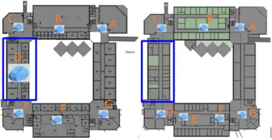
The BIM methodology depends on common, interoperable formats, but also on the controlled information sharing that breaks down information silos. In the current case, a BIM model of the campus is being developed by the campus Facilities Management team [10]. This model, shown in Figure 2-5, includes the complete geometrical description of the building including all room names. To make it useful to this application
more information was added, namely: elevators and stairs were modeled, beacons were modeled with all relevant location, all areas of the building were parametrized as walkable and non-walkable. The software used for the development of the BIM model was Autodesk’s Revit version 2019.
Figure 2-5 - 3D section views of the BIM model of ISCTE-IUL’s Building 1 – Sedas Nunes.
To extract information in the format demanded by the application, the Dynamo scripting language [11] was used. This visual programming language gives access to Revit API which allows for the manipulation and export of information in XML format, namely a list of rooms with their coordinates, name, floor and building; a list of beacons with coordinates and id information and the coordinates of the nearest stair and elevator, and automatically generated images of the walkable regions in each floor.
2.2.1 Maps for orientation
The navigation space in large buildings such as schools, public buildings or shopping centers is frequently complex, comprising rooms and corridors, stairs, escalators, lifts and ramps. Traditional architectural drawings such as floor and site plans, elevations and cross sections and more natural perspectives can be used, with adaptations, to aid in the navigation.
A floor plan, Figure 2-6, is a rectangular projection from above showing the arrangement of spaces of a level of a building, as seen if a horizontal section is cut through a building typically at 1.20 m above floor level. It shows anything that could be seen below that level: the floor, walls, windows and door openings, stairs from the floor until the section level and sometimes furniture. This is the most commonly used kind of representation in orientation. In general, the public is used to this kind of drawing, but a considerable proportion of users have difficulty in reading plans.
Figure 2-6- Hand-drawn floor plan of an apartment (left) and a Schematic cross-section of a multilevel building (right).
Elevations and cross sections, Figure 2-6 (right) as an example, are rectangular projections in the horizontal direction. The difference between them is the while elevations display the exterior of the building, cross sections show the interior, as seen as if a vertical plan cuts open the building. They are a valuable way to illustrate the relationship between levels of the building, but not very often used in navigation.
A more sophisticated category comprises the several kinds of three-dimensional projections. These are more easily read by lay users since they present a more natural way of showing the interior of buildings, walls, doors, and windows, passages, and furniture. Finally, the first-person view, as popularized in action games, allows users to relate what they see on the screen with reality. It is increasingly being employed, but it is much harder to implement since it demands a more precise location, a more detailed, 3D, description of the building and more powerful 3D graphics processing.
The choice of which elements are represented in the drawings and their level of detail is important in navigation. Most structural and construction details, materials and element thickness are not valuable in this scenario, but prominent decorative features or floor and wall colours or lining materials may be. On the other hand, visual aids such as human figures, shadows, transparency, exploded perspectives, enlargement of evident features or animations, even if not rigorous, give the observer a better grasp of the environment and direction.
Mobile Application Development
In this section, we describe 2 different types of programming languages to develop a mobile App. In the end, we conclude what is the most appropriate programming language to this project approach, with a verdict.
2.3.1 Swift
Developed by Apple in 2014, this programming language is general-purpose, multi-paradigm, compiled programming language. It is possible to create Apps to iOS, macOS, watchOS and tvOS, most of the equipment produced by Apple. It is an open source language. “Swift is the result of the latest research on programming languages, combined with decades of experience building Apple platforms. Named parameters brought forward from Objective-C are expressed in a clean syntax that makes APIs in Swift even easier to read and maintain” [12].
2.3.2 Android Studio
Based in Linux [13], Android is also an Open Source operative system bought by Google in 2005. This platform able the developers to create and implement applications to smart devices, like tablets, smartwatches or smartphones. A comparative study made in 2016 [14], mentioned that Android OS shares 86.2% on the whole market. It means that most of the people use Android as OS in their smartphones.
Figure 2-7 - The Android software stack/architecture [15].
As an Open Source software, Android made available his own Integrated Development Environment (IDE) – Android Studio – to all the people that need/want to create their own mobile Apps. Holds its own dedicated Software Development Kit (SDK) and development tools – Android Developer Tools (ADT). Several companies are adopting this platform because there are many people using smart devices with Android, the budget to develop applications it is usually low and, and has high potential for customization (Open Source).
2.3.3 Mobile Application Development Verdict
Developing in Android Studio would avoid a budget investment of an Apple laptop/desktop and because it is an open source, and available to several OS types. A
is available right now to build this project proposal). Also, as it is referred in section 2.3.2, most of the people, that holds a smartphone, use Android as a mobile operating system. For these reasons, Android Studio is going to be our choice to do the mobile App development.
The A* Path Finding Algorithm
A star, or A*, hold the objective of calculating lowest route/path cost from a current/initial point which is called node, to the destination node out of one or more possible nodes. It is based on an evaluation function: f(n) = g(n) + h(n). The h(n) is optimal path cost estimate from node n to the destination node and g(n) is described as the current cost from the current/initial node to any node n, with other words, the optimal path cost finding.
A* traverses the map, it follows the path with the lowest cost while keeping alternative nodes in a sorted priority queue. If a node being traversed has a higher cost than another encountered node at any point, it discards the node with the higher-cost and traverses the lower-cost node instead. This process continues until the goal is reached.
The provided map can be configured with two types of components: nodes and obstacles. To each node will be provided a cost, depending on the initial and destination node but for obstacles, it is not provided any cost so the A* does not consider keeping it on its queue. Figure 2-8 describes, in an objective way, the basic concept of A* algorithm as a flowchart.
Database
In this project, there is a need to have a database (DB) to store all the information that is needed for this proposed ILS. The database can be implemented in one of the two available options: External or Local.
2.5.1 External Database
The DB is implemented on a physical Server or in a Cloud. The advantage of having an external DB is that every information is not stored locally so it won’t affect the device performance. The disadvantage is that creates a dependency of the internet need to the mobile App and can be compromised when there is no WiFi or 3G/4G/5G access.
2.5.2 Local Database
The DB is implemented locally on the device. The advantage is that it doesn’t need internet connection to request data from the mobile App to the DB. The main disadvantage affects the performance of the device substantially and could overload the device memory if there is a huge amount of data to store.
2.5.1 Relational Database Management Systems
There are several Relational Database Management Systems (RDBMS), the most relevant on the market are MySQL [17] and Oracle [18]. Considering the Table 2-2, My SQL has more advantages than Oracle so it is going be used as RDBMS.
2.5.2 Data Storage Verdict
When having External Server Database, there is a need for always having a data transfer/internet access, and if there is no internet access for some moment, all the ILS can be compromised. For this reason, a Local Database is our choice to manage the storage part in this proposed ILS. The Database is just going to be populated when the user installs the Find Me! App.
Related Projects
In this section, it is going to be analyzed projects that implemented an ILS in a complex building with the different available IL technologies.
2.6.1 ILS based on QR Code technology
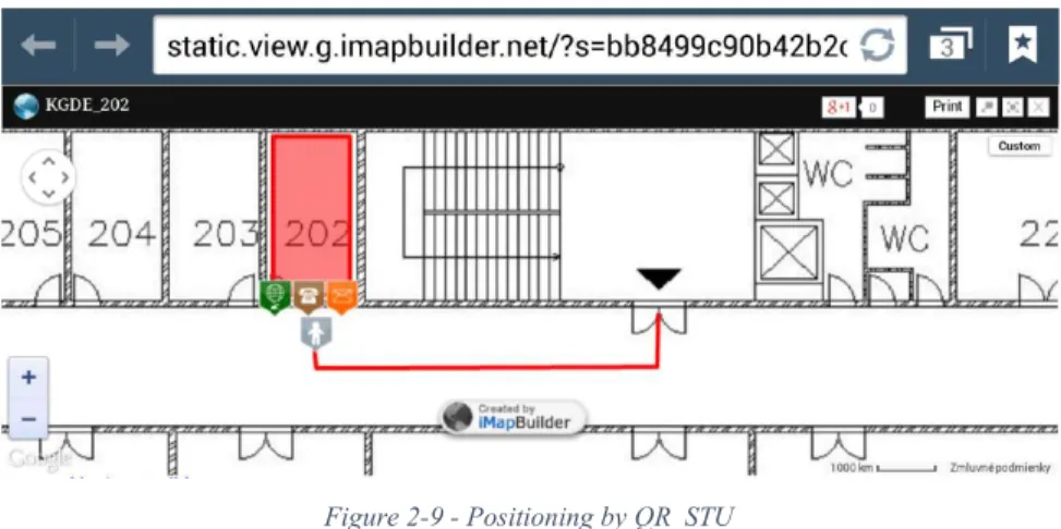
Ilkovičová, Ľ., Erdélyi, J. and Kopáčik, A. proposed an Indoor Location System using QR codes. The QR codes were positioned on several places of the Block A, Faculty of Civil Engineering building - Slovak University of Technology in Bratislava. It was developed a Java mobile application for Android OS named QR_STU, besides the download and installation of this App, the user needs to find the closest QR code and scan it with QR code reader that is already configured in QR_STU App. The scanned QR code returns an URL that allows identification of the user's location. With this URL, the application redirects to an external server, where an interactive map is stored where is already the painted current location of the user. To know how to get to the intended destination, the user just needs to select the room that he wants to go, after that a path is drawn from current user location to the selected destination and able the user to choose some icons to know more information about the destiny room. In Figure 2-9, there is an example of QR_STU working, where the destination is the room 202.
Figure 2-9 - Positioning by QR_STU
With this concept, it is not possible to continuously give orientation to the user because it only shows the user the first current location and the destination, if the user gets lost need to scan another QR code to know where he is, which can be a significant problem as User of usability this ILS.
2.6.2 ILS based on NFC technology
Busra OZDENIZCI, Kerem OK, Vedat COSKUN, Mehmet N. AYDIN planned an Indoor Location System applied with NFC tags [20]. The NFC tags are placed and distributed for all over the building, and a smartphone is used as an NFC reader. The ILS user interface is presented on a mobile App. Inside the building, the user seeks for the NFC tag and read the it with the Indoor Navigation App, using his smartphone camera. The read tag returns an URL that will be sent to a Map server that will interpret it and responds the map floor that corresponds to the tag position, which is the same as the user’s current location. The map is processed and converted to a link-node model with topological relationships - composed by roads, corridors, ways, the path between buildings, rooms, halls, stairs, lifts, and doors - on the mobile App side. Rendering the map with the user’s location on it, the user is allowed to choose the destination. Having these two locations, a Dijkstra’s pathfinding algorithm calculates the shortest path between them, as a background process. In the end, it is shown the map with the calculated way between the destination and the position of the tag. If the user wants to update his current location of the map, needs to read another NFC tag. Figure 2-10 represents what is written above in this section.
Figure 2-10 - ILS App’s Flow Chart [20]
The negative part of implementing NFC tags technology is that the user needs to get his smartphone very close to the tag (which decrease the user usability). The orientation path is always the same from the first moment that he reads the tag until he reaches the destination. If he wants to confirm if he is in the right way, needs to read tag by tag to update it.
2.6.3 ILS based on WiFi triangulation
A paper published by Zhao Kai Li Binghao and Andrew Dempster in 2013 consisted of an ILS using WiFi Triangulation to get a location of, in this case, a laptop. It was tested in on the 4th floor of the Electrical Engineering Building at UNSW (University of New South Wales), Sydney.
As the name describes, the WiFi triangulations consists on a location estimation of a device based on geometric properties of triangles. Several WiFi Access Points (AP) are implemented on the building, the laptop can receive the WiFi signal - the time of arrival (TOA), the angle of arrival (AOA) and the received signal strength (RSS) - from each WiFi AP that is in its range. With the content of each WiFi signal, is possible to calculate the distances between the laptop location and the WiFi APs. Having the location of three or more WiFi APs, the location of the laptop can be calculated/estimated by triangulation.
The precision and the building structure are important factors that can determine the quality of the ILS using WiFi. Internet Access and data transfer are needed, so when the bandwidth is low, it can compromise all the system and make it unpredictable or even useless.
2.6.4 ILS based on Beacon technology
A paper [21], made by Xin-Yu Lin, Te-Wei Ho, Cheng-Chung Fang, Zui-Shen Yen, Bey-Jing Yang and Feipei La, describes an Indoor Location System, using Beacon technology, applied to a Hospital Building. This ILS is divided into three main parts:
- Patients’ Mobile App side: The patients need to install a mobile App and after that, they will be able to be located, through the implemented beacons that cover all over the hospital building. Depending on the patient location, the intersected beacon sends data to the mobile App which sends it directly to the server that will convert it to a Location;
- Server Side: This server is like a middle tier that makes the connection between the two users side: Patients and Medical Staffs. This side holds a that Database that storages all the patient’s data and all the information from the location of the beacon as well. When received the location data from the App, does a search in its database looking for a beacon that matches the data sent from the App and returns a location. Having the location, directly send it to Medical Staffs Devices; - Medical Staffs Devices side: Besides showing all the patients data (like condition, name, age, etc.) it also shows the patients current location through the hospital map.
Having this ILS implemented, certainly allows the doctors, and probably security staff as well, to always know where the patients are.
This example of ILS, applied with Beacons Technology, is very similar to what it intended to do in this project but holds a difference – only shows the position/location of the user. In our project, instead of having just a current location of the user, we have the destination, the current location and the calculated shortest path between them. The positive way of using Beacon technology is that is always possible to receive data from the beacons (if building holds beacon coverage) which allows the implementation of an ILS with “live” and synchronized information.
Chapter 3 Find Me! Conceptual Modules
Based on the defined objectives in section 1.2, the primary research idea in this project is to use a simplified approach where the location is based on beacons location and defined range. The location indeed can be combined with map information to give a more accurate indoor position. Also, BIM models can allow 3D views, which can be helpful information.
Find Me! Overview
A mobile application, named Find Me! App, was developed to integrate beacons and BIM models in order to show the user location and the path that he/she needs to do to the destination, through a smart device. The most important and crucial parts of Find Me! App are the user’s current location and the inserted user’s destination. Having calculated these two locations, a Path Finding Algorithm (A* Search Algorithm Type [22]) calculates the shortest path between these two points and draw it on a map with the objective of guiding the user to his destination. When the user intersects another beacon region, the drawn path is updated with a new user’s current location.
Giving a brief description of what is intended to do in this App, when the user runs the Find Me! App, it will automatically identify the user’s location. This background process will be implemented with Beacons Technology: when the user is inside of a beacon region will be able to collect the data from the beacon. The received data will be translated as location and will show it on a map as a current location of the user. Having the user’s current location, the user has the option to insert the destination room and based on that, the mobile App calculates the shortest way between the current location and the destination, using a Path Finding Algorithm. The calculated way is shown on the map and is updated step-by-step (when intersected a new beacon) to increase the usability of App-User until he reaches the intended room. If the user chooses not to follow the given path and claim another option, the App will recalculate another way to the chosen destination. This mobile App also holds some extra features like:
- User Locomotion Option: Depending on user condition, it can be chosen, when the current location is on a different floor than the destination, the option of going by
- Intersect Orientation Photos: after calculating the shortest way between the current location and destination, it is going to be available, on the Find Me! screen, some photos of that path that the user needs to do to reach the destination.
This current work aims to help people with the complexity of the layout of many buildings problems/doubts. Implementing an ILS with input from Building Information Models complemented with BLE beacons can satisfy the user’s needs. The BIM model entity will be responsible for generating rooms, beacon location data and map floors to the mobile App that was developed – Find Me! App. Beacons are going to be configured with specific data, and placed, based on geometrical concepts, to provide a current live location to the user, through the mobile App.
This project will have three kinds of users in order to make it functional. So before beginning the application description, we need to describe each of them to have a brief knowledge, in order to understand what comes next. Each user roll holds an outstanding job that is dependent on the other user's type to implement a functional ILS.
- End Users: any person who has installed the Find Me! App, and to do it, just need to have a smartphone with OS Android to launch the mobile application;
- System and Database Administrators: this kind of users are responsible for generating Maps and input data to the mobile App, like rooms and beacon location data. They also need to configure, for the first time, each beacon and physically implement each of them. These users will build or reuse a 3D model of the building, in our test case – ISCTE-IUL building. Having the 3D model done, it is possible to aggregate attributes to all kind of components that are present in the model. In our solution, it will be added attributes to entities as follows:
- Rooms: name of the room, Building Number, Floor Number, and Location Room coordinates;
- Stairs: location coordinates, building, and floor; - Elevator: location coordinates, building, and floor;
- Beacons Location: MAC address, IBeacon protocol specification (UUID, Major, and Minor), Location coordinates, the radius of Beacon Region (broadcasting power in dBm unity), nearer stairs and nearer elevator; - Paths: which paths are walkable or not and which are permitted for some
kind of users’ type. All the aggregate attributes can be generated from the BIM model, as well as maps. These will be used in our project to generate
- Developers: develop and do the maintenance of the mobile App – Find Me! code.
The information referred above about each user role can be observed in Figure 3-1.
Figure 3-1 - Find Me! use cases diagram.
3.1.1 User Roles
The proposed ILS has the following users type: End User, developers and System and Database Administrators. In this section, we describe the role of each user.
End User
This ILS concept is intended for users that have a smart device, such as tablets or smartphones. The smart device needs to have an Android Operating System (OS) with Android 4.3 (JELLY BEAN MR2) as a minimum software development kit (SDK) target to install Find Me! App. This mobile App is developed for outsider and insider people of the entity (in our case of implementation example – ISCTE-IUL), so there is no Log In or Sign In need.
The Get Orientations action (see Figure 3-1) consists in using the developed mobile App – Find Me!, so the next content is going to describe the features of the mobile App. When the user runs the Find Me!, it scans for the closest beacon and after that, the user has two options to insert the destination (Insert Destination action, see Figure 3-1), as we can observe in Figure 3-2.
Figure 3-2 - Destination insertion mode options.
Choosing FIND ROOM mode, the user must write the destination as is implicit in Figure 3-3.
Figure 3-3 - FIND ROOM option.
Otherwise, if the user chooses the FINDFAST option, is able to choose quick spots like closest WC, food (canteens and bars), ATM, academic services and security station. As can be seen in Figure 3-4.
Figure 3-4 - FIND FAST options.
After having the two locations, current location, and destination, it will be shown to the user, the Orientations View, Figure 3-5 is an example of an experiment.
Figure 3-5 - Orientation View example.
In this activity the user is able to use the next features: - Path : The path that the user needs to do; - Current Location : To identify where the user is;
- Stairs or elevator : When the destination is located on a different floor, or even in a different building that needs to use elevator or stairs, these two buttons are going to be shown on this screen. By default, the Find Me! redirects automatically to the closest stairs. If the user wants to go by elevator, just need to press the elevator button, and it shows a newly calculated route to the closest elevator as we can see in Figure 3-6;
Figure 3-6 - Elevator button selected.
- Home : when selected, returns to the insertion mode activity (see Figure 3-2), with the objective of changing the room destination;
- Orientation Photos : With this feature, it is possible to check some important photos of the path that the user needs to do to reach the destination. In this way, the user can confirm that is on the right way. Pressing this button changes the layout to get the same photos but with the ability to zoom the pressed photo as we can verify in Figure 3-7. Pressing button will redirect to Orientations View screen again;
Figure 3-7 - FIND PHOTOS view
- Next/Previous : These buttons only appear when the current location floor is different from the destination floor. Clicking on the next button, the user can check where is the inserted destination on the corresponding floor. Clicking previous does the opposite, returns to current location floor map as the Figure 3-8 shows.
and was developed for Android operating system as a target. All the internal entities present in Front End and Back End Mobile App modules were implemented by this user role. When there is a need to fix a bug or add new features, this user type is going to do that kind of work.
System and Database Administrators
This user type holds an important role in this project: is responsible for implementing the external module of this project: Beacon Installation Process (see Figure 3-9).
In the BIM model entity, Create Structure 3D model action (see Figure 3-1), a 3D model of the building is generated, and attributes are aggregated to each room, beacon, stairs, and elevators (or more objects if needed). Having added all the required attributes, it is possible to extract that aggregated data in the form of tables and generate map floors (as .PNG files) to the Find Me! App. This process is represented as Generate Beacon and Rooms Data action and Generate Maps Floor action in Figure 3-1. Every time that a new element is added to the building (i.e. a room number changes, a new door is inserted) this user needs to add it in BIM model (and its attributes as well) and generate the data tables and PNG files. In other words, this user’s role also includes the maintenance of this entity. This part is explained with more details in section 4.1.3.
To implement the Beacon entity, this user needs to configure and place the beacons (see section 0 to see how it is done) which are the represented Beacons Configuration and Beacons Physical Placement action in Figure 3-1. After the implementation of this module, this user is also responsible for the maintenance of each placed beacon.
System Architecture
In this section, the system architecture of this project is described. The primary objective of this project is to develop a mobile application that will provide on-time orientations in order to satisfy and increase orientations quality to the user inside of a complex building like hospitals, museums, airports or faculties.
The Find Me! project can be described as three main modules, represented in Figure 3-9, where is identified the main system modules:
- Beacon Installation Process: This process is used as an initial installation process, where we try to find the number of beacons to use into the building,
- Front-end Mobile App: This is the user interface (UI) side, in this module the user is able to observe dynamic orientations elements like: Map with the optimized path to reach the destination; Crucial Orientation Photos to confirm if the user is in the right way; Destination insertion; Options to help the user to get the orientations more understandable.
- Back-end Mobile App: This module holds a Local Database that stores the beacons and the rooms data, this kind of data is populated from .CSV files and it is stored locally when the user installs Find Me! App. A Beacon Manager that scans for the closest beacons and manages the data that comes from each beacon that is intersected by the smart device. A Map Manager, as the name indicates, manages which stored map(s) floor is going to be returned to the user interface. The map floors, generated by BIM model, are also stored locally when Find Me! the App is installed on the user’s smartphone. Also has a Path Finding algorithm that calculates the shortest path between two locations.
3.2.1 Beacon Installation Process
In this section, we describe the Beacon Installation Process module which includes Beacons, BIM model entities, and the Beacon Physical Placement process.
Beacons
These BLE devices are responsible for sending data that is going to be after received by the End User smartphone (as a BLE signals receptor) that is going to be after converted as user current location by the Find Me! App. To validate the source of each BLE signal, each beacon needs to be configured and placed separately by System and Database Administrators in order to distinguish each beacon separately. As long as the End User smartphone receives a different BLE signal when walking through the building, the user current location is updated in Find Me! App.
Beacon Physical Placement
The role of this process is to get the quantity of beacons needed, the position where each one is going to be placed (in each floor) and the broadcasting power configuration needed in order to avoid BLE signals overlap and achieve a good ILS performance. If there is BLE signals overlap the correct user location cannot be assured. An external mobile App was developed to test the beacons Behaviour inside of a building, named NearestBeacons App (see section 0 – NearestBeacons App).
In BIM Model entity, it is possible to identify all the exits/entrances, halls/path intersections, stairs and elevators, and corridors centre. With that information, it is possible to apply Beacon Placement rules and Beacons Distance Rules (see section 0 – Beacon Location Rules) to have a successful Beacon Installation Placement process.
BIM Model
This is a 3D model of the building that includes all the elements that are present in the building. In this model, per each walkable and not walkable path, rooms, elevators, stairs and beacons positions, different attributes are set, depending on each type of the object. Having all this data set, it is possible to export all the object locations, attributes and interrelationships in alphanumeric format and also each map floor as PNG files. This exported data is going to be used in Find Me! App as input data.
A proper API is used to extract data from available BIM models. When selecting the building, as a parameter, and the information that we want to extract (Beacons
positions, rooms, paths, and map floors), this API exports the beacons and rooms as .CSV files and the map floors as PNG files.
3.2.2 Mobile App Back End
In this section we discuss all the implemented background logic, developed in Android Studio. The current location, destination, returned map floor and the shortest path, are calculated in this module and returned to the Front End Mobile App module.
Beacon Manager
It holds the objective of managing all the beacons that are intersected by the receptor. This entity calls an Estimote API that organizes the intersected beacons by RSSI from the highest value to the lowest, for other words, order the signals from the closest beacon to the furthest. It also extracts the data that comes from each BLE signal that is sent from the closest beacon. Having this feature from the Estimote API, there is no need to develop a handler for the intersection BLE signals.
The intersected beacon data is after sent, directly, to the Local Database entity to run a query and convert it, as the user’s current location.
Local Database
This entity receives the Rooms and Beacons .CSV files from the BIM Model entity and locally stores each file content in the corresponding table – Room and Location respectively. This storage process, only happens when the user runs the mobile App for the first time.
The Room table holds all the required data to identify a room as a destination, and Location table is where all the beacon data/configuration values are stored in order to give the current location of the user. Receiving an inserted destination string from the user, or beacon data, it is possible to run a query and return a destination location, or a current user location in case of beacon data.
Maps Manager
location and destination of the user. Having decided which map floor needs to be returned, sends it, with the current location and destination as well, to the Path Finding Algorithm entity.
Path Finding Algorithm (PFA)
This is a standard implementation of A* algorithm, that receives, as input, the current user location, the user destination and the map floor that sent by Maps Manager entity and calculates the shortest path between the two given locations. After having calculated it, the shortest path is returned to Orientation’s View entity.
3.2.3 Mobile App Front End
This module presents all the orientation elements that are shown to the user, through the smartphone screen. It was also developed in Android Studio. It’s here where it’s possible to see (through the smartphone screen) the orientations that the user needs to reach the destination - the map with the current location, destination and the shortest path that the. In addition, the orientation photos and the activity where the user can choose the destination.
Orientation’s View
This entity holds the objective of rendering all the orientation elements to help the user to find out the inserted user destination. It receives, from Maps Manager, the map floor, the shortest path from PFA entity and renders this both input parameters in a single element – an ImageView. With the given shortest path, this entity can also calculate the orientations photos - the FINDPHOTOS elements. The FINDPHOTOS shows to the user the spots that he/she needs to pass/go through to reach the destination.
User Interface
A simple entity, asks to insert the user’s destination, or just select a FINDFAST destination (see section 4.2.2 – User Interface, to learn what is FINDFAST option). This information is after sent to Local Database entity to be converted as a location.
Chapter 4 Find Me! Implementation
In this section, it is going to be described how both entity types (external and internal) of the Find Me! App were implemented and what is the dependency of each one, and also their role in this developed ILS.
Beacon Installation Process
This section explains how the Beacon Installation Process (Beacons and BIM entities, and Beacons Physical Placement process) are implemented and how they provide, to Find Me! App, information/data to support user localization.
4.1.1 Beacons
To understand how the beacon works it is essential to explain its characteristics.
BLE signal parametrization
- Broadcasting Power and Range: Broadcasting Power is the power with which beacon broadcasts its signal. The range is described as the area where the BLE signal can be intersected/received by other smart devices. Broadcasting Power directly impacts the signal range. High power values mean that the range is going to be bigger/longer. The Broadcasting Power can be set from -40 dBm (minimum) to +4 dBm (maximum) – corresponding to a minimum range of 2 meters and maximum range is 70 meters, without obstacles between the Beacon and the receiver;
- Advertising Interval: The beacon’s transmission packets can be configured in a restrict interval, this interval is the time when the beacon is “sleeping”, which means how long the beacon will be freeze until sending another IBeacon packet. For example, if the interval configured is 100ms, it means that the beacon will broadcast its signal once every 100ms (or 10 times per second). It can be set from 100 ms to 2000 ms. Choosing the interval can affect the battery life of the equipment: when the interval is low, more packets are sent, which means that the
Beacon Identification Parametrization (using the IBeacon Protocol)
The IBeacon protocol [23] was developed by Apple in 2014. This protocol enables the configuration of the data that is going to be sent in each BLE signal. In each IBeacon packet it is possible to configure the following fields:
- UUID: “16 bytes, usually represented as a string, e.g., “B9407F30-F5F8-466E-AFF9-25556B57FE6D”;
- Major number: 2 bytes, or an “unsigned short”, i.e., a number from 1 to 65,535; - Minor number: 2 bytes, same as Major.
This protocol is suitable for this project because, in each BLE packet, three fields are sent so it is possible to have more beacon data combinations and also be more specific when identifying the beacons signal origin.
BLE Signal Characteristics
The Received Signal Strength Indicator (RSSI), is the strength of beacon’s signal as received on the smart device. This is related to distance and Broadcast Power, i.e., the strength depends on the distance and broadcasting power values. Considering the maximum Broadcasting Power, +4 dBm, the Received Signal Strength Indicator range from approximately -26 (close distance, few meters) to -100 (40-50 meters). The RSSI can be used to estimate the distance between the device and the beacon. Table 4-1 shows the approximate values of the distance, in meters, corresponding to broadcasting power values in dBm unity.
Table 4-1 – Broadcasting Power values converted to Maximum Range in meters.[24]
Broadcasting Power
(dBm) Maximum Range (meters)
-40 2 -20 3,5 -16 7 -12 15 -8 30 -4 30 0 50 4 70
4.1.2 Beacon Physical Placement
Before the beacons configuration, there is a need to evaluate the building(s), as a structure, in order to get the number of beacons that we need and where these are going to be placed. This process holds the objective of getting a good correlation between a good ILS performance and a low beacons budget.
Beacon Propagation tests
These tests investigate the BLE signal propagation in concrete situations of a building with traditional reinforced concrete slabs, beams, columns and concrete, masonry and light-construction walls, as well as architectural features such as mezzanines, stairs, etc. The main questions being investigated in this section are:
- is there BLE signal overlap in the same floor? - is there BLE signal overlap between floors? - is there BLE signal overlap in long corridors?
- is there BLE signal overlap between floors with mezzanines?
These tests allow us to make conclusions to achieve good location performance from the BLE signals returned by the placed beacons. To perform the tests a mobile application was developed, as described in the following section.
NearestBeacons App
A mobile App called NearestBeacons was developed by the author based on the Estimote API [25]. This auxiliary application has the objective of evaluating the BLE signal, depending on the position of the user, as a monitor of BLE signals intersection. This App, when scanning and detecting one or more BLE signals, print the following fields of each signal order by signal strength (RSSI) on the smartphone screen:
- Major and Minor: to identify which beacon we are evaluating;
- Measured Power: “indicates what is the expected RSSI at a distance of 1 meter to the beacon.” [26];
- RSSI: Signal strength value that depends on distance and broadcasting power [26].
of NearestBeacons App showing two intersected beacons ordered by RSSI value, with the corresponding fields referred above.
Figure 4-1 - NearestBeacons scan values example.
BLE Signal Propagation Test Results
In this section, we evaluate the beacons behaviour in an indoor environment. With this BLE signal propagations tests, we expect to make conclusions about BLE signals overlap situations and which external factors act as, and offer, BLE resistance. Figure 4-2 shows where each beacon was placed over the floors of ISCTE-IUL’s Edificio 1 in order to evaluate different beacons behaviour situations.
Figure 4-2 - Floor no 0, 1 and 2 (left to right) with placed beacons.
In this first approach, we physically placed 22 beacons and every beacon was configured with a broadcast power of -16 dBm, which means that holds approximate of 7 meters of radius coverage. The beacons were placed on the ceiling of each floor. Figure 4-3 shows a beacon placement practical example.
Case 1: External factors – Slams density
This case holds the objective of getting conclusions about external factors as density of the slam between floors. In Figure 4-4, there is a blue rectangle that identifies the zone that we are focusing in this test case.
Figure 4-4 - Test case 1 layout. Floor 0 (left), floor 1 (right).
In this test case, we evaluate the BLE signal of ED1P0D (Major: 1 and Minor: 13) and ED1P1D (Major: 1 and Minor: 11) that are placed on the ceiling of floor 0 and floor 1 respectively. The signal strength values, taken from the nearest beacon App, were taken in 2 positions one from each floor (0 and 1) in a vertical line above each beacon.
Figure 4-5 shows where the user was, when taking the values (left) and also shows a NearestBeacons App screenshot(right) on floor 0. Observing these values, it is possible to confirm that the density of slam between floors does not block the BLE signal because we are getting both beacons BLE signals. The API used in the NearestBeacons App is the same used in Find Me!, so it organizes the signal from the highest RSSI values to the lowest, in this case, ED1P0D comes on the top of the list, and the next one is ED1P1D which is what is intended.
With these facts, it is possible to conclude that there is a need, if the density between floors has no effect on BLE signal, to have one beacon for each floor position to make sure that the Find Me! the App does not get BLE signal from the wrong floor, which implicit a wrong given current location of the user.
Figure 4-5 - Test Case 1 values, Floor 0, user position (left), NearestBeacons App results (right).
Case 2: External factors – Steel plate as a BLE blocker.
In this test case, we evaluate the steel as a BLE blocker. We placed the beacon ED1P1D (Major: 1 and Minor: 11) on the floor 1 ceiling with a steel plate (20x20cm) square with 5mm of thickness on the top. Figure 4-6 shows a practical example of the material mentioned in this Case 2.
Figure 4-6 - Beacon Placement with a steel plate on the top example.
Figure 4-7 shows the zone that we are studying in blue color. Keep in mind that no beacon was placed on floor 2 for this test case.
Figure 4-7 - Test case 2 layout. Floor 1 (left), floor 2 (right).
Figure 4-8 shows where was the user, when taking the values (left), and NearestBeacons App screenshot (right). The position was on floor 2 vertically align with the beacon ED1P1D, in floor 1. As we can observe, NearestBeacons App didn’t intersect any BLE signal, so it is possible to assume that the steel plate square worked successfully as a BLE blocker between floors.
Case 3: Testing BLE overlaps with mezzanines.
In this test case, we evaluate what is the behaviour of 3 beacons (placed on the ceiling of each floor), when having mezzanines between floors. Each beacon is vertically aligned in the same position. Due to mezzanines, there is a hole that crosses the 3 floors, which can be checked in Figure 4-9 in yellow and the zone that we are studying in blue colour.
Figure 4-9 - Test case 3 layout. Floor 0 (left), floor 1 (middle) and floor 2 (right).
The beacons applied in this test were: ED1P0A (Major: 1, minor: 3), ED1P1A (Major: 1, minor: 1) and ED1P2A (Major: 1, minor: 5). The values presented in Figure 4-10 and Figure 4-11 were taken from floor 1 and 2 respectively and in the same position on both floors.
![Figure 2-7 - The Android software stack/architecture [15].](https://thumb-eu.123doks.com/thumbv2/123dok_br/18664333.913388/32.918.280.686.99.694/figure-android-software-stack-architecture.webp)
![Table 4-1 – Broadcasting Power values converted to Maximum Range in meters.[24]](https://thumb-eu.123doks.com/thumbv2/123dok_br/18664333.913388/54.918.309.606.730.974/table-broadcasting-power-values-converted-maximum-range-meters.webp)