Repositório ISCTE-IUL
Deposited in Repositório ISCTE-IUL:
2018-07-20Deposited version:
Post-printPeer-review status of attached file:
Peer-reviewedCitation for published item:
Bendas, D., Saari, L., Coutinho, C., De Juan Marín, R., Gisbert, J. B. & Lopes, L. (2017). Distributed software development of a cloud solution for collaborative manufacturing networks. In 23rd
International Conference on Engineering, Technology and Innovation, ICE/ITMC 2017. (pp. 741-749). Funchal: IEEE.
Further information on publisher's website:
10.1109/ICE.2017.8279959Publisher's copyright statement:
This is the peer reviewed version of the following article: Bendas, D., Saari, L., Coutinho, C., De Juan Marín, R., Gisbert, J. B. & Lopes, L. (2017). Distributed software development of a cloud solution for collaborative manufacturing networks. In 23rd International Conference on Engineering, Technology and Innovation, ICE/ITMC 2017. (pp. 741-749). Funchal: IEEE., which has been published in final form at https://dx.doi.org/10.1109/ICE.2017.8279959. This article may be used for non-commercial purposes in accordance with the Publisher's Terms and Conditions for self-archiving.
Use policy
Creative Commons CC BY 4.0
The full-text may be used and/or reproduced, and given to third parties in any format or medium, without prior permission or charge, for personal research or study, educational, or not-for-profit purposes provided that:
• a full bibliographic reference is made to the original source • a link is made to the metadata record in the Repository • the full-text is not changed in any way
The full-text must not be sold in any format or medium without the formal permission of the copyright holders.
Serviços de Informação e Documentação, Instituto Universitário de Lisboa (ISCTE-IUL) Av. das Forças Armadas, Edifício II, 1649-026 Lisboa Portugal
Phone: +(351) 217 903 024 | e-mail: [email protected] https://repositorio.iscte-iul.pt
Distributed Software Development of a Cloud
Solution for Collaborative Manufacturing Networks
Dan Bendas, Leila Saari
Data-Driven SolutionsVTT Technical Research Centre of Finland Ltd. Oulu, Finland
{Dan.Bendas | Leila.Saari} @vtt.fi
Rubén de Juan Marín, Josep Bernabé Gisbert
Distributed SystemsInstituto Tecnológico de Informática, ITI Valencia, Spain
{rjuan | jbgisber} @iti.es
Carlos Coutinho
Instituto Universitário de Lisboa (ISCTE-IUL), ISTAR-IUL, Caixa Mágica Software, CMS
Lisbon, Portugal [email protected]
Luís Lopes
Research & Development Caixa Mágica Software, CMSLisbon, Portugal [email protected]
Abstract— Distributed software development poses extra
difficulties in terms of communication, coordination and awareness. Those difficulties usually imply more time consumption that causes productiveness reduction deriving finally in delays. So, projects where such kind of development is needed have to deal with them in order to ensure the success of the project. The case project has adopted this development approach due to its nature. The main goal of the project is to develop a cloud solution for enhancing collaboration and transparency between manufacturing companies forming a collaborative network. In order to implement it, the overall solution has been divided into several pieces, having many interdependencies among them. Thus, different working teams geographically spread from different organizations have participated in the implementation, integration, verification and validation tasks. This paper explains how the case project has organized the working teams, infrastructure, procedures and practices to guarantee the success of the project.
Keywords—distributed software development, development environments, cloud software development, working teams, infrastructure, procedures and practices, micro service architecture
I. INTRODUCTION
The evolution and widespread adoption of ICT technologies during the last years have triggered what is widely recognised as a new industrial revolution in the manufacturing industry world. This process is leading to the development of more complex information system where different ICT technologies are integrated for providing more advanced features to industries. This usually implies the participation of many people, with expertise in different areas, belonging to different companies that habitually are geographically distributed; in other words distributed software development. Even if one single third party contractor is in charge for the entire solution, still certain components will need to be connected with IoT devices or proprietary legacy systems, which are physically bound to certain locations, leading to distributed development activities.
Building solutions based on this paradigm implies an added effort to coordinate the evolution of the different teams and to evaluate the quality of the produced code. Moreover, when the multiple pieces of software get together to build the applications and solutions, there is the need to ensure their proper interconnection, binding and interoperability of the composed solutions. Often this task is hard because of differences in the paces of development of the different teams, or there are different interpretations of the requirements, or simply the modules have different integration needs or semantics. This is commonly due to communication problems between the various parties involved in the development and deployment of solutions.
This paper explains how the common distributed software development problems have been addressed in the case project execution through work organization, used infrastructures and procedures and practices established. The paper is organized as follows: Section I introduces key motivation factors for this research. Section II describes the state of the art of distributed software development research. Section III presents the context, both i) the external trends and technologies that made the case project possible, and ii) the case project itself as well as its solution architecture, platform and developers. Section IV introduces the actual development process applied, highlighting partitioning of work, inter-team coordination practices, and also cloud-specific software development tools. Section V discusses observations from the process and section VI concludes.
II. DISTRIBUTED SOFTWARE DEVELOPMENT RELATED WORK Distributed software development is associated with difficulties stemming from both human and technical factors. Jiménez et al. [1] identifies the most reported ten challenges of distributed software from a systematic literature review: communication, group awareness, software configuration management, knowledge management, coordination, collaboration, project and process management, process support, quality and measurement, and risk management.
The research leading to these results is ongoing in the “Cloud Collaborative Manufacturing Networks” (C2NET) project, which received funding from the European Union’s Horizon 2020 research and innovation programme under grant agreement No 636909.
Gutwin et al. [2] analysed the impact of group awareness for distributed software development in the context of open source projects, finding that adequate levels of coordination can be achieved by using text based tools like email lists, chat tools, and source code management logs.
Ramesh et al. [3] discuss the challenges of applying agile development methods in distributed project, noticing that practices in three areas need to be adapted: communication, control and trust. Several findings reflect those of this paper, for example the benefits of on-site visits and need for enhanced coordination mechanisms.
Grinter et al. [4] presents a thorough characterization of forces involved in geographically distributed R&D projects of large industrial companies. They identify four co-location models: by functional area of expertise, by product structure, by project steps and “customization work”.
Paasivaara and Larssenius [5] studied several industrial cases of globally distributed software development, one finding being that inter-personal relationships and face-to-face meetings are essential for project success. In [6] Pesola and colleagues discuss advantages of early verification and validation and how to apply such techniques in distributed projects. From the point of view of the solution to be obtained [7] describe a software application similar to the C2NET solution in terms of numerical methods and application domain.
III. CONTEXT
This section introduces the overall trends and technologies that influence the distributed software development activities in the case project. Also the project is introduced as well as its solution architecture, platform and developers.
A. General trends and technologies
The evolution and widespread adoption of ICT technologies during last years have enabled a new industrial revolution. This revolution based on the massive adoption of ICT by industries in order to improve their efficiency being promoted by governments and private organizations under different initiatives. These initiatives have been coined under different terms, like Industrial Internet in United States, Industrie du Futur in France, Industria Conectada 4.0 in Spain, or the most well-known in Europe, Industry 4.0 (Industrie 4.0) in Germany [8].
One enabler is Internet of Things (IoT) defined here as the interconnection of physical objects using common Internet technologies. Production and distribution chain entities like manufacturing machinery, vehicles, containers, warehouse equipment, etc. are connected to Internet and real-time data about their availability, location, operational status, technical condition, etc. is provided. In comparison with previous technologies like industrial networks or SCADA, IoT uses open protocols, mass-produced hardware, and wireless networking thus considerably lowering the threshold for adaptions in terms of cost, technical difficulty and vendor lock-in. One challenge in IoT adoption is the vast amount of data resulting from devices deployed in the field - data that needs to be collected, filtered, stored, analysed and utilized.
One proposed solution for managing such vast amount of data is cloud computing, which refers to a style of providing computing resources for networked services in form of virtual environments. Cloud vendors control large pools of physical hardware (possibly distributed over several geographical locations), partition those dynamically using virtualization technologies, and rent computing capabilities (like CPU power, database storage, disk storage, content delivery, specialized environments, etc.) to their customers, usually in a flexible, pay-per-use manner. In turn, this allows cloud customers to offer computing-intensive, responsive, and reliable services at reduced costs. Savings result from efficient utilization of resources, on-demand up and down scalability, and reduced equipment investments.
In the cloud paradigm, there are different ways of classifying solutions from different perspectives: i) level of application domain flexibility, and ii) deployment type. Firstly, based on their level of application domain flexibility services can be classified into Infrastructure as a Service (IaaS), Platform as a Service (PaaS) and Software as a Service (SaaS). Solutions for Industry 4.0 are usually of SaaS type, making use of existing PaaS and/or IaaS services. Secondly, cloud deployments can be public, private or hybrid. Private clouds have the hardware located in the premises of a single organization and its services are available only for internal usage. This configuration may be favoured by customers with privacy and data protection concerns. Hybrid cloud deployments combine elements hosted in a private cloud (for security reasons) with elements running in a public cloud (for benefits of cost, and performance).
At the same time, manufacturing industry is fighting with constant, radical and global changes. Companies need to re-think their business models, from innovative business collaboration networks, and adopt efficient ICT tools to survive the changes [9]. Also, [10] lists totally eleven success factors of an SME, where the top three are: digital solutions, industrial internet solutions and new business models. For the small- and medium size enterprises the investment is expensive and risky to do alone [11] as they have to face many barriers like: i) Factory floor automation and robotics, ii) Manufacturing IT systems, and iii) Digitalization of processes – Cyber Physical Systems (CPS) in Table I [10]. Joint efforts and increased collaboration are needed to overcome such difficulties
Table I. BARRIERS OF DIGITALISATION IN MANUFACTURING SMES ADOPTED FROM [10] Factory floor automation and robotics Manufacturing IT systems Digitalization of processes – Cyber Physical Systems (CPS)
No “of the shelf” technology available – no business case
Investment risk – costs
vs benefit Too low technology readiness level Lack of specialized
development resources
Process fit – need of integration and tailoring
Interoperability of systems and devices Investment risks – no experimentation possibility Lack of applied standards, legacy systems Investment risk – speculative benefits
This is why collaborative networks become one of the most natural ways for SMEs to take benefit of digitization while decreasing the risks and barriers they have to face with. The collaborative network has a variety of heterogeneous entities that are geographically distributed [11] The nodes of this network are willing to co-operate to achieve a mutual win-win situation. Camarinha et al. [12] present the interaction maturity level matrix having four building blocks: Networking, Coordinated networking, Co-operation, and Collaboration. In their matrix the interaction maturity level increases when the integration level increases from communication and information exchange though complementary goals and alignment of activities for mutual benefits towards joint goals and responsibilities.
The collaborative networks ensure constant feedback circuit and unbroken communication between product designers, engineers, manufacturing facilities and customers [11]. Thus, for the manufacturer the collaboration provides shorter delivery times, better speed and consistency of schedules, higher usage of production resources and even energy savings.
B. The Project
The case project is Cloud Collaborative Manufacturing Networks (C2NET), an EU H2020 project funded from Technologies for Factories of the Future in 2014 [13]. The project creates a cloud-based platform that will enable collaboration between the members of a supply chain network. This collaboration is achieved through: i) the supply network optimization of manufacturing and logistic assets based on collaborative demand, purchasing-, production- and delivery- plans, and ii) monitoring the current situation of the agreed plan comparing it to expected situation, notifying about significant deviations and suggesting most appropriate actions.
In this way, the C2NET solution integrates several features allowing: i) the data collection from company facilities including both legacy systems as ERPs or IoT devices and data homogenization according to the C2NET reference meta-model, ii) optimization of plans through using an optimization algorithm suggested by the platform through a wizard process (selected from a battery of near 100 algorithms), and iii) situation monitoring through model comparison of the expected situation according to the agreed plan and the real situation and agility suggesting actions in front of relevant deviations. This enables the members of a supply chain to collaborate within the cloud-based platform for improving the efficiency of their entire value chain.
The C2NET has four different industrial pilots around Europe to cover various needs of industries. The main goals of the pilots are summarized in Table II. The automotive pilot has a supply chain of first and second tier manufacturer producing car parts to their customer. The dermo-cosmetics pilot is a global actor having several production and logistics sites. In Portugal the SME network is willing to increase collaboration of purchases and transportation. The manufacturer of hydraulic and lubrication systems will add transparency to both its suppliers and customers.
Table II. MAIN GOALS OF THE C2NETPILOTS
Pilot Focus
Automotive in Spain
Optimisation of the production sequencing plan, considering unforeseen changes in the customer demand plans.
Dermo-Cosmetics in France
Prevent and manage replenishment shortages in a collaborative process using on-line production and deliveries data.
Metalworking SME Network in Portugal
Production costs optimization through collaborative logistics and raw material purchases.
OEM of Hydraulic and Lubrication Systems in Finland
Production planning with increased transparency to customers and suppliers.
All the pilots expect to have positive business impacts. Optimization of production will save material costs, organize the usage of production resources (both people and machines), and enable on-time delivery for the customer. Joint purchases will decrease both material and transportation costs. Manufacturer will gain efficiency and customer experience will improve because of product deliveries in-time.
C. The Architecture
The architecture of the C2NET solution is composed by several elements: i) the C2NET middleware that is located in the company facilities for collecting information from legacy systems and IoT devices and sending them to the C2NET cloud-based platform, ii) the C2NET cloud-cloud-based platform that provides the business logic of the system (i.e., data homogenization, plan optimization and monitoring capabilities), and iii) external applications that can connect with the cloud-based platform for enabling user interaction in a smooth way. Fig. 1 depicts the elements of this solution. The overall architecture of the C2NET solution is presented in [14] and [15].
The C2NET cloud-based platform is the core element of this solution as it is in charge of providing the key features of the solution. It is important to highlight that a cloud based approach has been adopted because it allows to: i) have access to large IT resources when needed, especially for optimization algorithm execution, while preventing companies to make high investments in IT infrastructure, and ii) access from everywhere at any time to those features. Those two benefits are quite relevant for SMEs companies, the main customer target of this solution.
The C2NET cloud-based platform is mainly developed as a Software as a Service that runs on top of the ECloud Platform as a Service (PaaS) [16]. ECloud is a PaaS designed to manage the life cycle events of services deployed on it in an automated way. Thus the elastic services are adapting to varying running conditions with minimal effort and expense on the part of the C2NET developers, letting them focus on the development of the service itself, without getting bogged down by the details of service management tasks. The counterpart is that the C2NET developers have to follow the ECloud specification.
Sharing data between the partners is essential as without sharing data you cannot collaborate. In the C2NET there are four different types of pilots having several SMEs, some large customers and one huge manufacturing company. The companies are not willing to give access to their legacy systems. In order to retrieve sufficient data two optional legacy system (LS) hubs are provided. Thus companies have the control over their data. Also it has been agreed that each pilot will have a differently configured service instance and each company will have own encrypted database although they are using the common C2NET cloud service. In addition to this, both IoT and LS hub use https and certification.
D. The Platform for Elastic Cloud
The ECloud PaaS has been selected in front of other approaches (IaaS and other PaaS solutions) because: i) it hides the management of the underlying IaaS (being able to run on top of most used IaaS like Amazon EMC2 or OpenStack), and ii) it automates the Service Level Agreement (SLA) fulfilment. This latter characteristic is the one that really makes ECloud different to other existing solutions. In this way, based on a machine-readable SLA, ECloud is able to monitor the fulfilment of the SLA, and scale up and down resources in order to meet workload peaks and free resources when they are no more needed without human intervention.
The ECloud approach is to force service applications to fit a set of architectural patterns. In a nutshell, the ECloud specification [16] considers a service application as a set of interconnected components, each one playing a different role (micro-service) within the service. Those roles are scaled up and down at runtime by the ECloud instance in order to guarantee the agreed SLA.
Components contain both the code that implements their logic, as well as a description (component manifest) of how they can be connected to other components through the communication channels they require and provide. Those communication channels are the only one mechanism that the ECloud provides components (roles) to interact among them at runtime. For doing so, at service definition time (service application manifest) the service provider has to specify for each channel role to which other channel role is connected, just ensuring that required channels are linked to provided channels and detailing the kind of connector used (i.e., load balancer). Using the ECloud communication channels hide to component developers the complexity associated to handle at runtime a number of varying instances of each role (live instance of a component), just relying in the ECloud instance.
At runtime, once this service is deployed (through a service deployment manifest) in an ECloud instance, this instance makes use of the different facilities provided by the underlying IaaS solution in order guarantee the SLA without considering human interaction.
As it can be seen, the ECloud makes usage of different manifests. Those files provide information to ECloud instance to manage the whole life cycle of the service: creating and launching the instances of the roles (components) that compound them, and connecting them as detailed in order to provide the service functionality.
E. Developers
The group of SW development people in the project is quite heterogeneous. It is composed by members from 10 different organizations located in four countries (two from Finland, two from France, two from Portugal and four from Spain), in three different time zones. Moreover, their backgrounds and expertise are very different moving from IT companies, to technology (in production or ICT) research centres or university departments. For example, not all members were aware about the different aspects to be considered when developing for a cloud environment. All those factors have implied really different software development practices and ways of working that have emerged when aligning works and coordinating activities.
Thus, the project has had to deal with such heterogeneity trying to find out a delicate trade-off between ensuring that all of them were comfortable enough while ensuring the right progress of the development activities.
F. Summary of Context
The C2NET project generates a cloud based solution that enables supply chain collaboration from the source, make and deliver plan optimization points of views, and monitoring of the real execution on the agreed plans in the supply chain. A cloud-based approach has been selected because this solution is mainly intended for SMEs so usage of low cost solutions with reduced investment in IT infrastructure is required. The core business logic is implemented as a SaaS, more specifically a SaaS to be run on top of the ECloud PaaS.
As collaborative manufacturing networks are composed of multiple companies, it is expected that software development for associated collaborative solutions is distributed across geographical sites and organizational boundaries. Even if one single third party contractor is in charge for the entire solution, still certain components will need to be connected with IoT devices or proprietary legacy systems, which are physically bound to certain locations, resulting in distributed development activities. Software development is considered to be distributed if developers are situated in distinct locations (even as close as different parts of a large building), and when the locations are in different countries the process is considered to be “globally” distributed [17].
IV. DISTRIBUTED SOFTWARE DEVELOPMENT IN C2NET The work organization, methods and tools have been defined, selected and aligned in order to minimize the problems existing in distributed software development during the C2NET solution development. The next subsections provide more information about the working teams, infrastructure, and procedures and practices utilized while the solution was developed.
A. Working Teams
In order to facilitate development activities, the developers were organized in small teams avoiding a very hierarchical organization. The co-location model [4] adopted has been a mix of product structure and project steps. This organization was also used for adapting to the distributed characteristic of the project partners. In this way, several working teams were set up:
• Component development teams: each component had at most developers from two different partners. This allows more agile developments at component level. • Module integration teams: four different teams were
established for ensuring the right integration of the components composing each of the C2NET modules. Those teams took as inputs the components generated by previous teams releasing properly integrated components in a per module basis.
• Service integration team: this team was in charge of integrating in a single service all the components previously integrated by module integration teams. • Validation teams: two teams are in charge of
performing validation using the service prepared by the service integration team: one from a technical point of view, the other from a pilot point of view.
• Supervision team: this team is in charge of monitoring the evolution of component development and integration.
• Pilot teams: there is one team per industrial pilot and are representing the industrial end users and thus providing the requirements, preparing data and validation scenarios, and assessing the implementation of pilot services.
Although those groups usually work in their own (remote and distributed) locations, using mail and on-line meetings to coordinate their activities, from time to time Integration Camps (IC), from 3 to 5 days of length, have been organized. In these IC, the different teams have been able to solve together pending issues and fostering the development activities.
Besides, several development facilities were available to all (Git repositories, ticket system, blogs and wikis). Moreover, several integration and testing environments were prepared for facilitating those tasks. Also, several procedures and practices were agreed for coordinating their activities ensuring smooth integration of their works, and enabling at the same time, that each of those teams organized internal activities in the way they feel more comfortable.
B. Infrastructure
1) Project Repository
The C2NET developing source code is being hosted at the OpenSourceProjects.eu (OSP) web portal [18] developed in the EU-cofunded FP7 project called PROSE. The fundamentals of the portal strategy are similar than the ones seen in other portals like GitHub or Sourceforge, and it is based on Apache Allura technology [19]. Likewise, besides having as its main features the ability to create multiple code repositories (Git or SVN) [20]– [22], the portal provides a framework of collaborative resources and tools such as wikis, ticketing systems, blogs, forums and external links. The structure of the portal allows the creation of context-related projects, each permitting its own definition of a user list and the assignment of these users to a set of roles, which include a set of base roles e.g., administrator, developer, tester, user, but also allows the creation of new specific roles, which will be useful for the establishment of policies for controlling the access control to the project data. Each project can include one or more sub-projects, where each has its own set of related tools, but all are ruled and accessed by the same user set defined in the main project. Every sub-project and every tool in the portal can have its own access defined, determining which roles have rights to administrate, create, write or read its information.
The strategy for building the C2NET project in OSP was to split the project development progressively into modules, sub-modules and ultimately in components (tree-based development), where each module/component has its own hierarchical sub-project in the OSP. Each sub-project has a common structure, which includes a wiki with the sub-project title, a dedicated ticketing system for dealing with the matters of the scope of that sub-project (which can be used to raise issues and defects, but also suggestions, or even management of the sub-project), and if the project is a component (developing project which includes code), it has also one or more Git code repositories. For the C2NET project, a new project was created in the OSP [23] including Git code repositories. The project structure follows the structure of C2NET modules, see Fig. 2. Besides those, the project also includes a fifth sub-project "Support" which is targeted to help the C2NET developers to use transversal tools and policies, e.g., how to work with the own OSP, Configuration Management policies, Build policies, repository management, or Development Management.
The C2NET project in the OSP has additionally some more collaborating tools, like a ticketing system for the user community to provide suggestions and support on the whole project scope, links for the official C2NET Homepage and a special ticketing system for Development Management. This ticketing system provides a ticket-based reporting supervision to the project.
2) Integration and Testing Environments
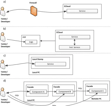
Different environments have been prepared in order to integrate the components and test/run the cloud service. The idea has been to provide to developers, integrators, and testers different ways to check that the software being developed fits the specified requirements. This section lists the four environments moving from the one that is equivalent to the real scenario (cloud infrastructure) to a distributed one that simulates the ECloud behaviour (Fig. 3). The environments are ordered for how close they are to the real working environment.
a) ECloud Stamp
This environment is a real ECloud running instance specially used for testing purposes. The idea is to use it as the final step before promoting a new version of a component to the official C2NET cloud service, testing in a real deployment. Moreover, in this case the developers and testers can interact directly with the deployed service.
b) Automated Testing Framework
This environment is based on a testing infrastructure and methodology for supporting the automatic testing of the generated service. This scenario is similar to the previous one in the fact of using an ECloud stamp. The main difference is that the service is tested by a test-service provided by the developer/testers that is also executed in the ECloud stamp, and there is no direct interaction by developers/testers. In such case, no executing infrastructure is needed in the developer/testers side. The testing infrastructure apart of the ECloud running instance is composed by a test repository, a script for launching the execution of requested tests, log (test results repository) and a log viewer.
c) Local Stamp
In order to speed up the integration and testing of new component features, a framework that facilitates local integration and testing was provided.
This environment named Local Stamp runs locally in a single PC and allow components of a service to interact using the communication channels of a real ECloud running instance. In this way, developers can check that component interaction behaves as expected in a fast way and solve detected issues. But, this emulation tool, as it runs in a single PC, does not provide emulation of cloud elastic capabilities (that is scaling up and down the number of instances of each component in order to guarantee the SLA for the service).
Fig. 3. Environments for Integration and Testing d) Integration Façade
An even more lightweight testing tool was provided to enable developers interact directly with their components. Named “Integration Façade” (IF), it differs from the previously presented solutions (a, b and c) by allowing the execution of individual components, and not complete services. Communication channels are exposed as HTTP connections. Developers can run explorative testing sessions accessing component API’s with a simple HTTP POST client. Several components running in IF (locally or remotely) can be inter-connected for small-scale interoperability testing. Mechanisms are included to provide mock-ups of the real ECloud facilities such as logging and service entry point. While the emulation of the ECloud environment is not completely accurate, the benefits of IF are reduced deployment and start-up time, and operational simplicity.
C. Procedures and Practices
As commented several procedures and practices were agreed for coordinating team activities, while trying to ensure a smooth integration of the components leading to the C2NET cloud service. Next subsections provide some details about those procedures and practices organized per type of activity.
1) Development and Development Management
Each working team can organize their internal works in the way they prefer in order to use the practices they are most comfortable with. Anyway, several practices and procedures were agreed for development purposes in order to facilitate traceability and support among different development teams. Those are: i) to follow the agreed generic component structure in order any partner has a basic knowledge when looking other components, ii) to ensure that the latest stable code version of
their component is available in the master branch of the component Git repository, iii) to tag each stable version they generate in order to have an easy access to previous stable versions, and iv) to document the channels the component provides and requires, and the components (and channels) they are expected to be linked with facilitating in this way the process of connecting and using different components.
From a development management point of view, a representative of each component development team participates in the bi-weekly supervision meetings, and updates the component evolution status discussed in there supervision meetings. This component evolution status is reported through the OSP tickets in the Development Management ticketing system. These tickets include some special fields like "% Complete" and a set of tags that allow the navigation through the modules scope. Upon updating the % complete and maybe including some specific comments, the supervising team only needs to quickly go through all tickets (usually spending around 2 minutes per ticket) and check the difference between actual completion and planned completion and the justification in the comments of the responsible. This method has a great advantage which is to store in the tickets history the whole evolution of the development pace.
2) Testing
The testing teams were suggested to perform unit tests at component level, component integration tests (using any of the provided environments) when checking the proper integration of different components, and service tests for testing the whole service. Each team can use the techniques and environment they prefer for testing. Moreover, it was also recommended to development teams not promote new version of components to their Git master branch until this new version has not passed all the related tests.
3) Verification and Validation
Verification and validation activities are carried out by several work teams in order to ensure the quality of the developed software (verification) and that it meets the end user specification (validation).
Verification and validation activities are performed at two levels: technical and functional. Technical verification assures that all components composing the service satisfy their technical requirements so that a) they can be deployed, b) they can intercommunicate and c) they respect the correct communication protocols at every connection point. Currently this is done manually by deploying a “generic” configuration of the service in a local stamp or in the ECloud stamp, verifying that certain activities can be performed through the graphical UI and by inspecting system logs. An automatic method is currently planned, which will use a continuous integration server (like Jenkins [24]) to rebuild, deploy and test the service whenever the source code of any component is updated.
Functional validation is performed by pilot teams by running the C2NET service configured for that particular pilot through a number of pre-defined scenarios. These validation scenarios
specify step-by-step activities to be performed by end-users with the expected results. Test data or real company data can be utilized. Each scenario step is mapped to a particular component, which enhances traceability between functional requirements and technical implementation.
V. LESSONS LEARNT
As stated previously, the distributed software development has been addressed through: i) small independent work teams with high level of autonomy, ii) a set of tools and environments for supporting their work and information sharing, and iii) several mechanisms and recommended practices for ensuring basic coordination among them using the defined infrastructures. After nearly one year and a half of distributed software development activity, the main lessons learnt are discussed in the following paragraphs.
A. Working teams
The observed efficiency and efficacy of the small working teams has shown certain variability, mainly derived from different member background and expertise than to the distributed nature of the project. But, overall working teams efficiency has been jeopardized due existing interdependencies among them while being distributed. In this way, this has required extra coordination that has reflected in more exchanged mails and the organization of many online conferences, which has reduced their productiveness. Besides, as mail and online conferences are not the best mechanism for discussing about complex topics it has been necessary in most occasions to devote more time – in terms of mails and more or longer conferences – than the initially expected.
These interdependencies among working teams has also provoked delays, when waiting for inputs from other working teams, implying a slower working pace. In this way, the IC organized (3 up to the moment, and 2 more planned) have revealed as one of the most valuable practices in order to coordinate and synchronize the different working teams, especially, the different development and integration teams in order to foster the generation of C2NET solution.
B. Infrastructure
In regard to infrastructure, the hierarchical organization of the C2NET project inside the OPS (with nested and self-contained OPS subprojects for modules and components) resulted in some difficulties finding the information in order to be aware about other working team activities, especially when monitoring the ticket evolution (feature implementation and component evolution). In other words, the initial compartmentalization having isolated working islands for the different working teams has shown generally speaking to be counterproductive in terms of facilitating partner awareness about development works, which is one of the main problems in distributed environments. To avoid this, a ticket reorganization was performed putting all them in the same ticketing system in order to facilitate pilot and supervision teams to control ticket evolution.
Considering integration and testing environments, developers have preferred to work on local environments (Local Stamp) that are more agile and faster than remote ones
(Automated Testing Framework). However, it has to be noted down that probably this has caused by some extra configuration steps that developers have to perform when using this remote environment.
C. Procedures and practices
From a point of view of procedures and practices, the ticketing system has not been used as much as expected, especially by the component development teams. The same has happened with the suggested tagging and code promotion policies. Thus, generally speaking the suggested procedures and practices have not been used as much as desired even when they would have been beneficial for the working teams in the long term. In fact, this has implied some extra coordination work among working teams performed mainly by email.
In this context, using the ECloud PaaS as the backbone platform to run the C2NET cloud part has helped to make component integration activities smoother. This is because cloud components are forced to follow the ECloud specification (which can be seen as a mandatory practice for development and integration working teams) imposing therefore its structure for integration activities. Nevertheless, the learning curve for many developers has been harder than expected. In regard to supervision, the initial supervision procedure based on a component coarse grain value although agile has not been able to reveal some existing delays due to natural trend to optimistic considerations. In order to face this, a new supervision strategy based on component features grain is being put in place.
VI. CONCLUSION AND FUTURE WORK
Experiences learnt in the daily work have shown that part of the working team organization, some infrastructures (tools) and procedures and practices have not worked as expected to overcome common problems in distributed software development. The main reasons that prevented some of them to be useful enough are due to: i) they are complex to use (e.g., Automated Testing Framework) or time consuming (e.g., tickets) and members do not see a clear return of investment in the short term and/or have other alternatives (e.g., Local Stamp or mails respectively), ii) procedures with subjective and coarse grained rules (e.g., supervision mechanism), and iii) being some of them just recommendations but without investing enough time to convince about their benefits. In some cases, this has forced to rethink how they should be used (ticketing system and supervision mechanism), make its usage easier, and communicated (tagging and testing practices) in order members are more committed to use them.
Other aspects have shown to be very fruitful in order to overcome those issues. On one hand, IC can be considered one of the best mechanisms to solve those problems. In order to maximize their worthiness they were planned in a regular basis (specifying a clear high-level goal for each one of them) but spacing them in such a way that working teams had time to advance in-between with their activities. Two or three weeks before each IC, participants agreed its specific agenda according to the pre-planned high-level goal and current issues preventing this goal to be achieved. If needed parallel tracks and sessions were planned according to the number of participants and issues to be solved. Then, in the face-to-face meetings, developers were
together during a whole week: to solve issues that can be hardly addressed in teleconferences and to foster integration activities. It was also important to nominate coordinators at IC and for each session to lead work, and especially for encouraging participation and ensuring liveliness in brainstorming and discussion sessions. On the other hand, selecting the ECloud PaaS as the C2NET base runtime has implied that its specification became a mandatory practice facilitating the integration works of cloud components.
As future work in the C2NET project context in order to master the distributed software development problems three following main actions can be highlighted. First, to use and validate the procedures and practices presented in this paper as well as some new ones proposed. Secondly, to think mechanisms and communication strategies that makes participants more eager to follow the recommended practices and apply them. Third, to analyse which practices have to be promoted from recommendations to mandatory and ensure its adoption in other European projects.
VII. REFERENCES
[1] M. Jiménez, M. Piattini, and A. Vizcaíno, “Challenges and Improvements in Distributed Software Development: A Systematic Review”, Adv. Softw. Eng., vol. 2009, pp. 1–14, 2009.
[2] C. Gutwin, R. Penner, and K. Schneider, “Group awareness in distributed software development”, in Proceedings of the 2004 ACM conference on
Computer supported cooperative work - CSCW ’04, 2004, p. 72.
[3] B. Ramesh, L. Cao, K. Mohan, and P. Xu, “Can distributed software development be agile?”, Commun. ACM, vol. 49, no. 10, p. 41, Oct. 2006.
[4] R. E. Grinter, J. D. Herbsleb, and D. E. Perry, “The Geography of Coordination: Dealing with Distance in R&D Work”, in Proceedings of
the ACM Conference on Supporting Group Work, 1999, pp. 306–315.
[5] M. Paasivaara and C. Lassenius, “Collaboration practices in global inter-organizational software development projects”, Softw. Process Improv.
Pract., vol. 8, no. 4, pp. 183–199, Oct. 2003.
[6] J.-P. Pesola, H. Tanner, J. Eskeli, P. Parviainen, and D. Bendas, “Integrating early V&V support to a GSE tool integration platform”, in
Proceedings - 2011 6th IEEE International Conference on Global Software Engineering Workshops, ICGSE Workshops 2011, 2011.
[7] Y. Liu, X. Xu, L. Zhang, L. Wang, and R. Y. Zhong, “Workload-based multi-task scheduling in cloud manufacturing”, Robot. Comput. Integr.
Manuf., vol. 45, pp. 3–20, 2017.
[8] “Industrie 4.0 , Smart manufacturing for the future”, Berlin, 2014. [9] P. Ahokangas, H. Alila, H. Helaakoski, V. Kyllönen, T. Lehtimäki, I.
Peltomaa, V. Seppänen, and H. Tanner, Collaborative Business
Networks of the Future, vol. 2. 2015.
[10] J. Paasi, Ed., Towards a new era in manufacturing, VTT Tecnol. VTT Technical Research of Finland Ltd, 2017.
[11] B. Andres, R. Sanchis, and R. Poler, “A Cloud Platform to support Collaboration in Supply Networks”, Int. J. Prod. Manag. Eng., vol. 4, no. 1, p. 5, Jan. 2016.
[12] L. M. Camarinha-Matos, H. Afsarmanesh, N. Galeano, and A. Molina, “Collaborative networked organizations – Concepts and practice in manufacturing enterprises”, Comput. Ind. Eng., vol. 57, no. 1, pp. 46–60, 2009.
[13] “C2NET Project Site”, 2017. [Online]. Available: http://cordis.europa.eu/project/rcn/193440_en.html. [Accessed: 01-May-2017].
[14] C2NET “D2.8 – 3rd detailed components design and APIs”, 2016. [15] R. Peña-Ortiz, B. Ramis-Ferrer, E. Miedes, A. Nieto, R. de Juan-Marín,
and J. L. Martínez -Lastra, “Towards a cloud-based platform for enabling supply chain collaboration”, in Cloud Collaborative Manufacturing
[16] SLAP team, “Building Services for the ECloud PaaS”, Valencia, ES, 2016.
[17] J. D. Herbsleb and D. Moitra, “Global software development”, IEEE
Softw., vol. 18, no. 2, pp. 16–20, 2001.
[18] “OSP” 2016. [Online]. Available: https://opensourceprojects.eu. [Accessed: 01-Nov-2016].
[19] “Apache Allura” 2017. [Online]. Available: https://allura.apache.org. [Accessed: 01-Apr-2017].
[20] J. Loeliger and M. McCullough, Version control with Git, 2nd ed. O’Reilly Media, 2012.
[21] S. Chacon and B. Straub, Pro Git, 2nd ed. Apress, 2014.
[22] C. M. Pilato, B. Collins-Sussman, and B. W. Fitzpatrick, Version control
with subversion, 2nd ed. O’Reilly Media, 2008.
[23] “C2NET repository home,” 2016. [Online]. Available: https://opensourceprojects.eu/p/c2net [Accessed: 01-Oct-2016].
[24] “Jenkins,” 2017. [Online]. Available: https://jenkins.io/. [Accessed: 01-Apr-2017].
![Table I. B ARRIERS OF DIGITALISATION IN MANUFACTURING SME S ADOPTED FROM [10] Factory floor automation and robotics Manufacturing IT systems Digitalization of processes – Cyber Physical Systems (CPS) No “of the shelf”](https://thumb-eu.123doks.com/thumbv2/123dok_br/18409255.894395/3.892.461.841.818.1007/arriers-digitalisation-manufacturing-automation-manufacturing-digitalization-processes-physical.webp)
![Fig. 1 depicts the elements of this solution. The overall architecture of the C2NET solution is presented in [14] and [15]](https://thumb-eu.123doks.com/thumbv2/123dok_br/18409255.894395/4.892.464.836.813.1047/fig-depicts-elements-solution-overall-architecture-solution-presented.webp)
![Fig. 2. C2NET Repository [23].](https://thumb-eu.123doks.com/thumbv2/123dok_br/18409255.894395/6.892.467.824.800.987/fig-c-net-repository.webp)